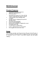
1
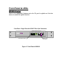
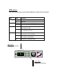
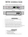
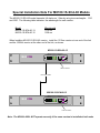
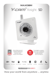
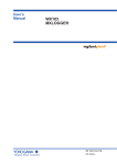
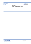
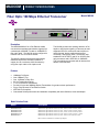
MAX COM
PRODUCT SPECIFICATIONS
Fiber Optic 100 Mbps Ethernet Transceiver
Model MX100
D
D
MX100 Fast Ethernet Transceiver
100 Base FX
Link/Act PWR
10/100
MDI
MAXCOM
MDI-X
TX
RX
FDX/Col 100
TX
Description
The MAXCOM MX100 is a Fast Ethernet media
converter that translates transmission signals from
a twisted-pair 100BASE-TX cable to 100BASE-FX
fiber optic cable. The MX100 can be configured to
transmit over one or two fiber strands.
The MX100 expands network data transmission
distances beyond the 100 meter limitation of
copper wire to a maximum of 80 kilometers by
using fiber optic cable in full duplex mode.
The MX100 provides auto-sensing detection of full
duplex or half duplex signaling. It has easy-to-read
diagnostic LED's for continuous status reports on
network speed, duplex media access control
connection, and network traffic. The MX100 uses
standard RJ-45 UTP/STP and SC or SC/APC fiber
optic connectors and is IEEE 802.3u 100BASETX/FX compliant and operates with all devices that
adhere to this standard.
Features
•
•
•
•
•
•
•
•
•
100Mbps Full Duplex
One 100BaseT Port
One 100BaseFX Fiber Port
80 Km Transmission Range
1 or 2 Fiber Strand Transmission
Provide full wire-rate 200Mbps Duplex Transmission for greater network performance
Plug-n-Play Ethernet & Fast Ethernet Switch
IEEE 802.3u Compliant
Guaranteed Switch performance and hardware compatibility with other Switches, Hubs and Adapter
Model Selection Guide
Model
Description
MX100-1S-SCA-40
MX100-1S-SCA-80
MX100-2S-SCA-60
MX100-2S-SCA-110
MX100-1M-SC-2
100Base Fiber Optic Ethernet Transceiver, 2 Port, 1 Fiber, SC/APC Connector, 40 Km
100Base Fiber Optic Ethernet Transceiver, 2 Port, 1 Fiber, SC/APC Connector, 80 Km
100Base Fiber Optic Ethernet Transceiver, 2 Port, 2 Fiber, SC/APC Connector, 60 Km
100Base Fiber Optic Ethernet Transceiver, 2 Port, 2 Fiber, SC/APC Connector, 110 Km
100Base Fiber Optic Ethernet Transceiver, 2 Port, 1 Fiber, SC/PC Connector, 2 Km
Other Connectors and Distances Available Upon Request
Application Drawing
100BaseT Network Switch or Hub
SD
ER
P
OW
T
UL
FA
M
E
OR
M
Y
R
IV
E
IT
E
CE
M UX LAB
SM
AN
TR
01
02
03
04
05
06
07
08
09
10
11
12
13
14
15
16
17
18
19
20
21
LANSWI TCH 2424B
22
23
24
AD DR ESS
12345678
IN
OUT
SER IAL
Work Station
Work Station
SD
PizzaSwitch
1
HS1
HS2
O K1
O K2
PS
2
3 4 5
6
7 8
9 10 1 1 12
CO NSOL E
CO L AC T ST A-
XYLAN
MAX COM
MAX COM
One Optical Fiber
Standards
IEEE 802.3u 100BASE-TX/FX Fast Ethernet
Connection Ports
1 Port UTP & 1 Port Fiber Switch;
1 RJ-45 100Mbps UTP port and 1 100Base-FX fiber port
Network Media
100 BaseT: UTP category 5
100 BaseT: SC 62.5/125 microns multi-mode Fiber cable
Crossover Push Button
LED indicators
1 crossover button for the UTP port
Power, Link/Activity, Full Duplex/Collision,100Mbps
Physical Dimensions
Environment
Input Power Requirements:
260mm x 44mm x 145mm
Temperature: Operating: 0C to 40C
Storage: -20C to 70C
Humidity:
Operating: 10% to 90% RH
Storage: 5% to 90% RH
Voltage: 110/220V Auto-sense Internal Power, USA
Registration
FCC Part 15 Class A, CE, UL, CUL, TUV, VCCI 1
Package Includes
•
•
•
•
Two Port 100TX - 100FX Transceiver
Power Cord
Rack-mountable hardware
Easy to follow owner's manual
System Requirements
•
IEEE 802.3 10BaseT Ethernet or IEEE 802.u 100BaseTX Fast Ethernet
Warranty
•
5 year limited warranty
MAXCOM
711 S. Carson St.
Carson City, NV 89701
Tel: (800) 493-2167
Fax: (209) 333-0388
User’s Manual
MX100 Series
MX100 Fast Ethernet Transceiver
100 Base FX
MAXCOM
TX
RX
Link/Act PWR
FDX/Col 100
10/100
MDI
MDI-X
TX
Fiber Optic Fast Ethernet Transceiver
MX100 Users Manual and Installation Guide
Section 1:
Overview
Section 2:
Installation Guide
Section 3:
Switch Configuration Procedure
Section 4:
Specifications
MX100 Overview
Product Features
Ÿ
Ÿ
Ÿ
Ÿ
Ÿ
Ÿ
Ÿ
Ÿ
Ÿ
Ÿ
Ÿ
One-channel media conversion between
100BASE-TX and 100BASE-FX
Fiber media allows:
multi-mode fiber using SC, ST, VF-45 or MT-RJ
connector; single-mode fiber using SC connector
Auto negotiation of speed and duplex mode
on TX port
One DIP switch for configuring fixed speed and
full duplex modes
Store-and-forward mechanism
Full wire-speed forwarding rate
Back-pressure & IEEE802.3x compliant flow control
Front panel status LEDs
One push button for uplink purpose
Used as a stand-alone device or with a chassis
Hot-swappable when used with a chassis
Ports
The Converter provides one TX port and one FX port. For the FX port, it
provides options of either multi-mode or single-mode fiber and a wide range
of connectors. For the TX port, it uses RJ-45 connector and full duplex
100Mbps.
Front Panel & LEDs
MDI/MDI-X button
There is one MDI/MDI-X button next to the TX port for uplink use. Push the
button to enable the uplink function.
Front Panel - Single Fiber with SC/APC Fiber Optic Connectors
MX100 Fast Ethernet Transceiver
100 Base FX
Link/Act PWR
10/100
MDI
MAXCOM
TX
RX
FDX/Col 100
MDI-X
TX
Fiber Optic Port (FX)
Figure 2: Front Panel of MX100
100Base-T Port
(Full Duplex)
LED Indicators
The LED indicators give you instant feedback on status of the converter:
LEDs
State
Indication
Power
Steady
Power on
Off
Power off
Steady
Connection at speed of 100Mbps
Off
Connection at speed of 10Mbps
Steady
A valid network connection established
LNK stands for LINK
Flashing
Transmitting or receiving data
ACT stands for ACTIVITY
Steady
Connection in full duplex mode
FDX stands for FULL-DUPLEX
Flashing
Collision occurred
COL stands for COLLISION
Off
Connection in half-duplex mode
100 (Mbps)
LNK/ACT
FDX/COL
Upper Row:
Fiber Optic Port LEDs
100 Base FX
TX
RX
Link/Act PWR
FDX/Col 100
10/100
MDI
MDI-X
TX
Lower Row:
100BaseTX LED Status
MX100 Installation Guide
Front Panel - Single Fiber with SC/APC Fiber Optic Connectors
MX100 Fast Ethernet Transceiver
100 Base FX
MAXCOM
Link/Act PWR
10/100
MDI
MDI-X
TX
RX
FDX/Col 100
TX
100Base-T Port
(Full Duplex)
Fiber Optic Port (FX)
Rear Panel
On / Off Switch
AC Power Connector
Installation Procedure:
1. Mount the unit in either an EIA 19" Rack, desk top or wallmount configuration.
2. Ensure that the unit is properly ventilated.
3. Connect AC power to the IEC Power Connector located in the rear of the unit.
4. Connect the Fiber Optic Connectors to the Fiber Span. Verify that the Link LED is
Green when a compatible 100BaseFX transceiver is transmitting over the fiber.
5. Connect the 100Base-TX port to either a PC, HUB or Switch that supports
100Base-TX Links. Verify that the LINK LED is GREEN. If the LINK LED is NOT
GREEN, toggle the front panel's MDI front from straight connection to a crossover connection.
6. When both the 100Base-TX LINK LED is GREEN and the 100Base-FX LINK LED is
GREEN, test the link by PINGing a known IP address on the remote end.
Troubleshooting Tips
1. 100Base-TX LINK LED is NOT GREEN
a. Try toggling the front panel MDI switch
b. Try a different CAT-5 Jumper
2. 100Base-FX LED is NOT GREEN
a. Verify that an Optical Signal is present
b. Try looping back a fiber optic jumper from the TX port to the RX Port
Special Installation Note For MX100-1S-SCA-80 Models
The MX100-1S-SCA-80 model transmits full duplex on 1 fiber by using two wavelengths: 1310
and 1550. The following table indicates the wavelength for each version:
Model
MX100-1S-SCA-80-13
MX100-1S-SCA-80-15
Wavelength
1310 nm
1550 nm
When Installing MX100-1S-SCA-80 version, install the 1310nm version at one end of the link
and the 1550nm version at the other end of the link, as shown.
MX100-1S-SCA-80-15
MX100 Fast Ethernet Transceiver
100 Base FX
MAXCOM
TX
RX
Link/Act PWR
FDX/Col 100
10/100
MDI
MDI-X
TX
1550 nm version
Fiber Optic Cable
MX100-1S-SCA-80-13
MX100 Fast Ethernet Transceiver
100 Base FX
MAXCOM
TX
RX
Link/Act PWR
FDX/Col 100
10/100
MDI
MDI-X
TX
1310 nm Version
Note: The MX100s WILL NOT operate correctly if the same version is installed at both ends.
MX100 Configuration:
100Base Transceiver, Full Duplex Switch Settings
Installation Procedure for Units with Configuration Switches:
1. Remove Power from Unit, remove AC power cord and remove Top Cover
2. Locate Configuration Switches.
If Configuration Switches not present, use the installation procedure for units without switches
3. For units with configuration switches:
a. turn S1, S3, S5 and S6 to ON (UP).
b. Verify that Switches S2 and S4 are OFF (DOWN).
4. Replace Top Cover and re-install the unit
Configuration Switches
(Facing Rear Panel)
Switch 1
S1
KENDIN
Top View
MX100 Fast Ethernet Transceiver
MAXCOM
Uplink
MX100 Front Panel