1
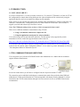
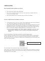
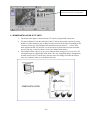
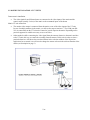
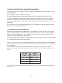
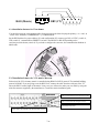
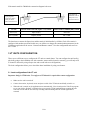
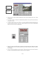
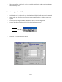
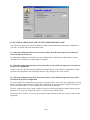
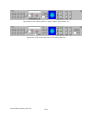
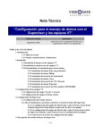
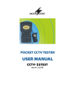
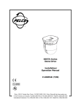
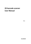
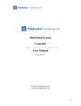
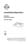
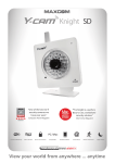
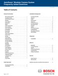
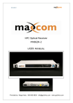
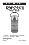
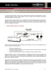
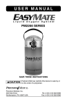
Technical Note “Configuration process to control domes connected to VT units with the Supervisor software handset” Revision date Application September 2005 Supervisor (3.61 and later) VT200 (3.5 and later) VT100 (1.8 and later) TABLE OF CONTENTS 1. Introduction 1.1 Note applicability 1.2 Tips, communications channels and limitations 2 Installation 2.1 Domes Installation at VT units 2.2 Matrix installation at VT units 2.3 Installations features of different domes 2.3.1 Installation features of Pelco_P domes 2.3.2 Installation features of Philips domes 2.3.3 Installation features of Sensormatic matrix 2.3.4 Installation features of Vicon domes 2.3.5 Installation features of VCL Maxcom matrix 2.3.6 Installation features of Panasonics domes 2.3.7 Installation features of Pelco matrix CM6700/6800 3. VT units configuration 3.1 Local configuration of a VT unit 3.2 Remote configuration of a VT unit 4. Supervisor configuration 4.1 Configuring the software handset 4.2 Including the remote sites in the Supervisor database 4.2.1 The unit configuration has been carried out remotely from the same Supervisor in which you want to include the remote site 4.2.2 The unit configuration has been carried out locally or from a different Supervisor and you know the password configuration 4.2.3 The unit configuration has been carried out locally or from a different Supervisor but you DO NOT know the password configuration 5- Software handset description 1/18 1. INTRODUCTION 1.1 NOTE APPLICABILITY If you have a Supervisor V3.61 and your units versions are 3.5 or later for VT200 and 1.8 or later for VT100 the configuration to control domes using the Supervisor software handset will be carried out by using the application interface and it is not required to change any file manually. If the versions of your unit and your software are included in the paragraph above continue reading this note. Otherwise, consult the note “Configuration process to control domes in VT200 units” (old versions) or upgrade your units and software up to the latest versions. Note: The VT100 units with previous versions to 1.8 do not support the dome control. There are two different methods to control domes using VT units: 1. Using a real handset connected to a Supervisor PC 2. Using the application control panel or software handset You can choose anyone, but not both at the same time. The first option is only supported by certain manufacturers. Please consult the supported domes table in the web: http://www.videosafe.net/ProductDocsNotes/VT_ProductDocsNotes/VTRNGPN05SP_DomeTable.PDF If your dome is not in the table or despite of being included you would prefer to use a real handset you have to choose the first option called “Transparent Channel”. If you want to get more information see the note: “The transparent channel in VideoSafe System”. 1.2 TIPS, COMMUNICATIONS AND LIMITATIONS You can connect up to 16 domes all of them from the same manufacturer or a matrix that can sometimes support different manufacturers. In order to control domes you will have to configure both, the Supervisor and the VT units. The connection can be established with whatever communication mode being used other than GSM and nullmodem in VT200, and nullmodem in VT100 (incompatible with domes control), although for a faster transmission the TCP/IP communication through a local area network (LAN) or an ISDN connection are recommended. 2/18 2 INSTALLATION Before beginning the domes installation you will need: Write down the dome model and the manufacturer. Write down the identification address of the dome. (refer to the dome user manual). This is not necessary when installing a matrix. Write down the number of the VT200 camera input you will use for each dome. In order to complete the domes installation you will need: A VT200 unit version 3.5 or later or a VT100 1.8 or later installed at the remote site and a Supervisor 3.61 version or later installed on a PC being used for the remote control. A Dome protocol adapter to RS232 to connect the dome to the unit and the instructions for its correct configuration (refer to the specific manual of your dome). If you are installing a single dome and it supports RS-232 protocol, you can connect directly the RS232 serial port of the VT200 to the dome. Please, refer to the dome manual for detailed instructions (e.g. Ernitec dome ICU model ). Note: In case of domes installation with VT100 it is highly recommended to connect pin 7 and 8 (RTS and CTS) in VT unit side, in order to avoid flow control problems with the protocol converter. You can connect both the VT unit directly to the domes or through a supported matrix In order to connect the video matrix to the VT unit to get images from different domes by turns using only one of the video inputs in the VT unit rear. To do this you will connect the monitor video-output with the video-input in the VT unit. If you want move to another dome you should choose the associated camera in the selector of the software handset . Camera selection when controlling a matrix. The control remains in the camera that is being visualized at that instant. On the contrary if you connect the domes directly to the VT unit (maximum 16) all of them have to belong to the same manufacturer. In order to move from one dome to another you should choose the associated camera in the Supervisor live video window. 3/18 Camera selection when controlling domes. 2.1 DOMES INSTALLATION AT VT UNITS The domes video signal is connected to the VT units by using the BNC connectors. You have to hardwire from the serial port of the VT unit to the protocol converter by using the RS-232 cable and then a pair of cables from the converter to the dome. Depending on the converter selected you will configure some parameters (speed, protocol …) or not. If the dome supports the RS-232 protocol, it is not necessary to connect the converter but in that case you can only connect one dome ( see the user manual of the dome). If the installed dome is able to go to a preset when an alarm is triggered, you can wire a VT unit digital output to a digital input in the dome. This way, through the proper configuration, an alarm wired to the VT unit not only cause the start of recording, also order the dome to move to a position in order to record the desired zone. 4/18 2.2 MATRIX INSTALLATION AT VT UNITS Domes-matrix installation. The video signals from different domes are connected to the video-inputs of the matrix and the control output (usually 2 wires) of the matrix to the commands inputs of the domes Matrix-VT unit connection: The monitor video output is connected from the matrix to one of the video inputs of the VT unit. In case of multiple monitors in the matrix you will use the output “monitor 1”. The COM port (RS232) is connected from the VT unit to the control or joystick input in the matrix. Depending on the protocol supported it could be necessary to use a converter. Other method could be connecting the video signal from the cameras (domes) to the matrix and also to the VT units, this way we ensure the recording from all cameras. In this case in order to select a particular dome we will choose the associated camera in the selection window of the Supervisor application, but to control it we will need to change the camera selector in the software handset of the matrix (see description in page 3). 5/18 2.3 INSTALLATION FEATURES FOR PARTICULAR DOMES Next we will present you different advises and configuration guidelines that we hope will help you in your installation process. 2.3.1 Installation features for PELCO_P domes The domes supported are those communicating using the PELCO-P protocol, not the PELCO-D one. All devices are configured with the “Direct Mode” protocol. The parameters to be set are the following: interface RS-422, Baudrate: 4.800 Baud, ByteSize=8, Parity=None, StopBit=0. The value 1 in Stopbit appears in data communications in the user manual of the dome but it is necessary to change it to 2 for correct functionality. The test was carried out by using a dome model DD5TAC-X The adapter used for this connection was the 485OT9L manufactured by B&B Electronics 2.3.2 Installation features for PHILIPS domes Philips domes support both RS-232 and Biphase. If you configure the domes to use RS-232 you only can connect 1 dome to the unit. If you want to control more than one dome you will need a RS-232 to Biphase adaptor supplied by Philips company. The configuration parameters are the following: Baudrate=9600, ByteSize=8, Parity=0, StopBits=2 y FlowControl=1 The family autodome and envirodome are supported and we have successfully tested the LTC0829/10 model. 2.3.3 Installation features for Sensormatic matrix You have to enter in the matrix configuration menu and select in the ports menu the option “KEYBOARD”. The communication parameters are the following: ByteSize=8 Parity=None, StopBits=1, FlowControl=None and 1200 baudrate. You must connect the VT unit and the Sensormatic matrix using a home-made cable. The end to be connected to the matrix is a RJ45 and the end to be connected to the VT unit is a DB9 with the connection below. VT unit Matrix DB9 RJ45 Pin nº2 RXD Pin nº 4 TXD Pin nº 3 TXD Pin nº 5 RXD Pin nº5 GND Pin nº 7 GND The VT unit connector is a DB9 and the matrix connector is a RJ45. The pin numbers are described in the next pictures. 6/18 5 4 3 2 8 5 6 1 7 RJ45 (Matrix) 4 3 2 1 DB9 (VT) 9 8 7 6 2.3.4 Installation features for Vicon domes You should connect the corresponding cables from converter to the dome keeping the polarity (+ to + and –to -) to the screw terminals: COMMAND IN + y COMMAND IN -. Set the DIP Switches for proper address (S1) and configuration (S2), camera type PAL or NTSC, (switch 1), VPS (switch 2), communication SIMPLEX (switch 3) and RS-485 or RS-422 depending on the converter/protocol chosen (switch 4). If you need to configure the converter, the communication baudrate is 4800 bauds. 2.3.5 Installation features for VCL matrix, Maxcom Each unit of the VCL telemetry matrix is controlled using RS485 or RS232 protocol. The standard building protocol is RS485. If you are going to use the RS232 one, connect the cable from the serial port of the VT unit to the RS232 control input of the matrix. In any case you will need to make your own cable by using the mini-din connector supplied by the manufacturer. Consult the matrix installation guide. Input to be connected to the serial port of the VT unit Input to be connected when using the converter Control output to the dome Video output to be connected to the video input of the VT unit 7/18 If you choose the RS485 you have to insert a protocol converter in the wiring from the VT unit (serial port) to the KBD1 input of the matrix. The communication speed is 9600 bauds. Configure the converter device if it is needed. Min-din plug to the KBD1 matrix input CONNECTION BY USING RS-485 CONVERTER T+ T+ RS-232---485 TTConverter Internal view (solder) Modem (serial) cable You can also connect the VT unit and the VCL matrix directly without using the protocol converter but always make sure that RS232 protocol is supported by the matrix. Consult the manufacturer user manual. In this case the matrix control input is labeled as RS-232- The wire connections are indicated below. RS 232 DIRECT CONNECTION Min-din plug to the RS232 matrix control input DB9 female plug to VT unit serial port. 5 4 9 3 8 2 7 1 6 9 pin plug external view Internal view (solder) 8/18 2.3.6 Installation features for Panasonic dome WV-CS850 Follow the user manual installation steps of the dome. There are two DIP switches on the camera. The 8-bit DIP switch is used to implement protocol selection, to specify the unit number and to select the communication parameters. Switch settings are read by the camera when the power is turned on, so to carry out the configuration make sure to turn it off and then turn it back on between each operation. Configure the camera with conventional protocol first. Then implement the parameters: Baudrate 19200, Data bit 8, Parity check None y Stop Bit 1 and finally enter the dome identity. Correct configuration Correct configuration The 4-bit DIP switch is used to select the ON/OFF termination and half/full duplex for RS485 communications. Configure the camera with Full Duplex for 485 communication. Correct configuration 9/18 2.3.7 Installation features for Pelco matrix model CM6700/6800 You can connect the VT unit and the Pelco Matrix directly by connecting the both serial ports as described below. It is not necessary to wire the T+ in the Matrix side. In order to configure the matrix to be able to receive control commands by using the RS-232 port you have to configure the microswitches as indicated below: The matrix is able to communicate with domes through the video coax cable by using the COAXITRON system. If the dome does not support this communication channel, you can also use the control outputs. The monitor video output MONITOR 1 has to be connected to any video input of the VT unit. Video coax cable Alarms and control inputs-outputs RS-232 plug to be connected to the serial port of the VT unit. 10/18 If the matrix model is CM6800 the connection diagram is the next: 9 pin plug from connection cable to serial port of VT unit. External view. 9-pin plug from connection cable to serial port of the matriz. External view. VT unit Matrix model CM6700 (inputs 7-12) COM2 Matrix model CM6800 (DB9) COM1 Pin 3 (TX) Input 12 (R+) Pin 2 RX Pin 5 (GND) Input 9 (GND) Pin 5 GND The baud rate to connect the Supervisor and the matriz is 9600 baudios by deffault. Check if the matrix is configured with another speed and in this case you will have to change the communication parameters in the VideoSetup application in the screen “Cameras and Remote control”. Save the configuration and send it to the VT unit. 3 VT UNITS CONFIGURATION. There are two different ways to configure the VT units to control domes. You can configure the unit locally ( physically going to the installation site with a monitor, mouse and keyboard) or remotely (you will only need to connect to the unit by using a Supervisor and to send it the new configuration). The local configuration allows you to check the dome installation by using a test button. 3.1 Local configuration of the VT unit Important: Only for VT200 units. To configure a VT100 unit it is required the remote configuration Make sure the unit is turned off Connect the monitor, keyboard, mouse and power cable of the VT200 unit and finally switch it on. When the unit is turned on, the application starts automatically. Close it and open the VideoTest program so you can tick the “Refresh” verification box to prevent the VT200 watchdog from restarting the unit. Take into account that the unit will stop recording and transmitting until the VT200 application is restarted. 11/18 Choose type of dome Choose camera and identification number. Select the type of dome installed, through the pop-up menu contained in the box: “Dome configuration”. If you want visualize or modify the communication parameters for a specific dome click on the “Comm data” button. To define a camera as dome, you will have to select the identification number through the popup menu in Dome Id section. If you have a matrix installed you can select any identification number for it has no effect on configuration. Display the image of each PTZ camera on the main viewer and click on the “Dome Test” button, verifying on the screen the movement performed by the dome (automatic movement Up Down, Left and Right) Close the VideoTest application and switch off the VT200 unit using the power button. Disconnect the mouse, the keyboard and the monitor, and then restart the equipment. 12/18 When you configure a unit locally you have to add the configuration to the Supervisor database. Consult the chapter 4.2.2. 3.2 Remote configuration of a VT unit Check that the unit is working and video signals and control (RS232) cables are properly connected. Connect to the unit from Supervisor. The name, password and IP address or telephone number are required. Open the Remote configuration dialog and click on: “Receive remote configuration”. Open the VideoSetup select the unit and click on the “Configuration button”. Click Click on the “ Cameras and remote control”. 13/18 Choose from the drop-down list, the model to which belong the PTZ cameras connected .To visualize or modify the default communication values click on: y To define a camera as a dome click on the checkbox of the column “Is dome?” and write the identification number in the next box. If you are configuring a matrix ignore this number because it does not affect to the configuration. y Click on the save button and close the VideoSetup application. y In order to send the configuration to the unit you have to connect to the unit and open the “Remote configuration dialog” and click on the “Send configuration” button. Once the unit has been restarted it will use the new configuration 14/18 4. SUPERVISOR CONFIGURATION 4.1 SOFTWARE HANDSET CONFIGURATION In order to configure your Supervisor application to control domes, follow these steps: Run the Supervisor application and click on the upper left corner of the Supervisor screen, which gives access to the Supervisor configuration . Click Click on the “Remote control” option of the configuration dialog Click If the option “Domes with software handset” is not ticked, mark it. 15/18 4.2 INCLUDING THE REMOTE SITES IN THE SUPERVISOR DATABASE You will have to update your remote site database with the domes and matrixes parameters configured in your units. To do this follow the instructions below. 4.2.1 The unit configuration has been carried out remotely from the same Supervisor in which you want to include the remote site No additional configuration is needed if you have configured the remote units to control domes from the same Supervisor in which you want to update its database. 4.2.2 The unit configuration has been carried out locally or from a different Supervisor and you know the password configuration Connect to the unit, open the Remote configuration dialog and click on the “Receive configuration” button. Open the unit configuration with VideoSetup and save it by clicking on the “Save” button. 4.2.3 The unit configuration has been carried out locally or from a different Supervisor but you DO NOT know the password configuration If you do not know the configuration password you will not be able to receive the unit configuration. Anyway run the VideoSetup application and open the unit configuration. A pop-up message will appear warning you that you will not be able to save the configuration. Click on OK and continue. Click on “Cameras and remote control” and choose the type of dome and mark the camera as dome giving a Id number to it. If you are configuring a matrix, it is not necessary tofill this field. Click on the “Save” button . A new pop up message will appear similar to prior one. Accept it and close the application. 16/18 5. Supervisor control panel description When connecting to a VT unit from your Supervisor, if the camera selected is a dome and you have carried out the configuration properly, the lower panel of your screen, which shows the alarm inputs and relay outputs, will be hidden behind the domes control panel display screen. This screen can be minimized by clicking on its upper right button. The appearance of the domes control panel varies from one dome type to another but the management is very similar for all of them: dome movement control with the mouse, zoom in-zoom out, focus, 180º turn, dome positions recording function, tours around the recorded positions, etc. The domes Kalatel, Ernitec and VCL and the VCL matrix, Maxcom have their own control panel. Other domes supported by the application have a generic control panel. There are two different generic panels one for domes and another for matrixes. The generic control panel for matrixes has a similar appearance to the domes one but the tours box is replaced by the camera selection one. Appearance of the dome control panel for an Ernitec dome Appearance of the dome control panel for a Kalatel dome Appearance of the control panel for a VCL dome Appearance of the control panel for a generic dome (Pelco_P) 17/18 Appearance of the control panel for a generic matrix (Sensormatic_m) Appearance of the control panel for a VCL matrix Maxcom DOCVSFTNOEN_050905_DomeConfig 18/18