1
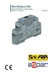
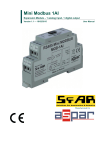
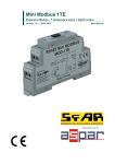
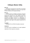
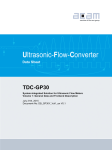
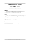
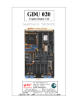
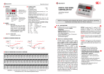
SDM-6RO
Expansion Module – 6 relay outputs
Version 1.0 — 5.02.2014
User Manual
Manufactured for
SDM-6RO
SfAR
User Manual
Thank you for choosing our product.
This manual will help you with proper support and proper operation of the device.
The information contained in this manual have been prepared with utmost care by our
professionals and serve as a description of the product without incurring any liability for
the purposes of commercial law.
This information does not release you from the obligation of own judgement and
verification.
We reserve the right to change product specifications without notice.
Please read the instructions carefully and follow the recommendations contained
therein.
WARNING!
Failure to follow instructions can result in equipment damage or impede
the use of the hardware or software.
Expansion Module – 6 relay outputs
User manual
© SFAR 2011-2013. All rights reserved.
Version 1.0 - 5.02.2014
2 z 16
SDM-6RO
SfAR
User Manual
1. Safety rules
•
Before first use, refer to this manual
•
Before first use, make sure that all cables are connected properly
•
Please ensure proper working conditions, according to the device specifications
(eg: supply voltage, temperature, maximum power consumption)
•
Before making any modifications to wiring connections, turn off the power supply
2. Module Features
2.1. Purpose and description of the module
The SDM-6RO module is an innovative device that provides a simple
and cost-effective extension of the number of lines of output with high current-carrying
capacity.
The module has 6 relay outputs. Each relay has three terminals: common
(COM), normally open (NO) or normally closed (NC), so that the unit is very flexible.
This module is connected to the RS485 bus with twisted-pair wire.
Communication is via MODBUS RTU or MODBUS ASCII. The use of 32-bit ARM
core processor provides fast processing and quick communication. The baud rate is
configurable from 2400 to 115200.
The module is designed for mounting on a DIN rail in accordance with
DIN EN 5002.
The module is equipped with a set of LEDs used to indicate the status of inputs
and outputs useful for diagnostic purposes and helping to find errors.
Module configuration is done via USB by using a dedicated computer program.
You can also change the parameters using the MODBUS protocol.
Expansion Module – 6 relay outputs
User manual
© SFAR 2011-2013. All rights reserved.
Version 1.0 - 5.02.2014
3 z 16
SDM-6RO
SfAR
User Manual
2.2. Technical Specifications
Power Supply
Voltage
10-30 VDC; 10-28VAC
Maximum Current*
DC: 200 mA @ 24VDC
AC: 250 mA @ 24VAC
Maximum power consumption DC: 4.8W; AC: 6VA
No of outputs
Relay outputs
Temperature
Connectors
Size
Interface
*
6
The maximum current and 5A 250V AC
voltage (resistive load)
10A 24V DC
Work
-10 °C - +50°C
Storage
-40 °C - +85°C
Power Supply
2 pins
Communication
3 pins
Outputs
2x 10 pins
Configuration
Mini USB
Height
110 mm
Length
62 mm
Width
88 mm
RS485
Up to 128 devices
Maximum current with active Modbus transmission, all outputs on
Expansion Module – 6 relay outputs
User manual
© SFAR 2011-2013. All rights reserved.
Version 1.0 - 5.02.2014
4 z 16
SDM-6RO
SfAR
User Manual
2.3. Dimensions of the product
Look and dimensions of the module are shown below. The module is mounted
directly to the rail in the DIN industry standard. Power connectors, communication and
IOs are at the bottom and top of the module. USB connector configuration and
indicators located on the front of the module.
91
45
110
42,3
35
110
88
Expansion Module – 6 relay outputs
User manual
© SFAR 2011-2013. All rights reserved.
Version 1.0 - 5.02.2014
5 z 16
SDM-6RO
SfAR
User Manual
3. Communication configuration
3.1. Grounding and shielding
In most cases, IO modules will be installed in an enclosure along with other
devices which generate electromagnetic radiation. Examples of these devices are relays
and contactors, transformers, motor controllers etc. This electromagnetic radiation can
induce electrical noise into both power and signal lines, as well as direct radiation into
the module causing negative effects on the system. Appropriate grounding, shielding
and other protective steps should be taken at the installation stage to prevent these
effects. These protective steps include control cabinet grounding, module grounding,
cable shield grounding, protective elements for electromagnetic switching devices,
correct wiring as well as consideration of cable types and their cross sections.
3.2. Network Termination
Transmission line effects often present a problem on data communication
networks. These problems include reflections and signal attenuation.
To eliminate the presence of reflections from the end of the cable, the cable must
be terminated at both ends with a resistor across the line equal to its characteristic
impedance. Both ends must be terminated since the direction of propagation is bidirectional. In the case of an RS485 twisted pair cable this termination is typically
120 Ω.
3.3. Setting Module Address in RS485 Modbus Network
The following table shows how to set switch to determine the address of the
module. The module address is set with the switches in the range of 0 to 127. Addresses
From 128 to 255 can by set via RS485 or USB.
Switch
Adress
SW1
+1
SW2
+2
SW3
+4
SW4
+8
SW5
+16
SW6
+32
SW7
+64
Ex. if switches 1, 3 and 5 are on than module addres is:
Address = 1 + 4 + 16 = 21
Expansion Module – 6 relay outputs
User manual
© SFAR 2011-2013. All rights reserved.
Version 1.0 - 5.02.2014
6 z 16
SDM-6RO
SfAR
User Manual
3.4. Types of Modbus Registers
There are 4 types of variables available in the module.
Type Beginning adress
Variable
Modbus
Command
Access
1
00001
Digital Outputs
Bit
1, 5, 15
Read & Write
2
10001
Digital Inputs
Bit
Read
2
3
30001
Input Registers
Registered
Read
3
4
40001
Output Registers
Registered
4, 6, 16
Read & Write
3.5. Communication settings
You can restore the default configuration by the switch SW8 (see 3.5.2 - Restore
the default configuration)
3.5.1. Default settings
You can restore the default configuration by the switch SW8 (see 3.5.2 - Restore
the default configuration)
Boud rate
19200
Pariti
Nie
Data bits
8
Stop bits
1
Reply Delay [ms]
0
Modbus Type
RTU
3.5.2. Restore the default configuration
To restore the default configuration:
•
turn off the power
•
turn on the switch SW8
•
turn on the power
•
when power and communication LED start blinking alternately than turn off the
switch SW8
Caution! After restoring the default configuration all values stored in the registers will
be cleared as well.
Expansion Module – 6 relay outputs
User manual
© SFAR 2011-2013. All rights reserved.
Version 1.0 - 5.02.2014
7 z 16
SDM-6RO
SfAR
User Manual
3.5.3. Configuration registers
Modbus
40003
Dec
2
Hex
0x02
Name
Baud rate
0 – 2400
1 – 4800
2 – 9600
3 – 19200
4 – 38400
5 – 57600
6 – 115200
other – value * 10
0 – none
1 – odd
2 – even
3 – always 1
4 – always 0
40005
4
0x04
Parity
40004
3
0x03
Stop Bits LSB
1 – one stop bit
2 – two stop bit
40004
3
0x03
Data Bits MSB
7 – 7 data bits
8 – 8 data bits
40006
5
0x05
Response delay
40007
6
0x06
Modbus Mode
Expansion Module – 6 relay outputs
User manual
Values
Time in ms
0 – RTU
1 – ASCII
© SFAR 2011-2013. All rights reserved.
Version 1.0 - 5.02.2014
8 z 16
SDM-6RO
SfAR
User Manual
4. Switches
ON
1 2
3
Switch
Function
1
Module address +1
2
Module address +2
3
Module address +4
4
Module address +8
5
Module address +16
6
Module address +32
7
Module address +64
8
Restoring
default settings
4
5
6
8
Description
Setting module address from 0 to 127
Restoring default settings
(see 3.5.1 - Default settings i 3.5.2 - Restore the
default configuration).
Expansion Module – 6 relay outputs
User manual
7
© SFAR 2011-2013. All rights reserved.
Version 1.0 - 5.02.2014
9 z 16
SDM-6RO
SfAR
User Manual
5. Front panel removing
To remove the panel and gain access to the switch, you must pry open the panel
using a thin tool (eg a small screwdriver) as in the picture below.
Expansion Module – 6 relay outputs
User manual
© SFAR 2011-2013. All rights reserved.
Version 1.0 - 5.02.2014
10 z 16
SDM-6RO
SfAR
User Manual
6. Indicators
Outputs 1 – 3 state
Communication
ON
1
2
3
4
5
6
7
8
mini USB
configuration
connector
Power supply
Outputs 4 – 6 state
Indicators
Power supply
Description
LED indicates that the module is correctly powered.
Communication The LED lights up when the unit received the correct packet and sends the
answer.
Outputs state
LED indicates that the output is on.
Expansion Module – 6 relay outputs
User manual
© SFAR 2011-2013. All rights reserved.
Version 1.0 - 5.02.2014
11 z 16
SDM-6RO
SfAR
User Manual
7. Module Connection
SHIELD
SUPPLY
Expansion Module – 6 relay outputs
User manual
POWER SUPPLY
© SFAR 2011-2013. All rights reserved.
Version 1.0 - 5.02.2014
12 z 16
SDM-6RO
SfAR
User Manual
8. Modules Registers
8.1. Registered access
Modbus
Dec
Hex
Register Name
Access
30001
0
0x00 Version/Type
Read
Version and Type of the device
30002
1
0x01 Switches
Read
Switches state
40003
2
0x02 Baud rate
Read & Write
RS485 baud rate
40004
3
0x03 Stop Bits & Data Bits
Read & Write
No of Stop bits & Data Bits
40005
4
0x04 Parity
Read & Write
Parity bit
40006
5
0x05 Response Delay
Read & Write
Response delay in ms
40007
6
0x06 Modbus Mode
Read & Write
Modbus Mode (ASCII or RTU)
40009
8
0x08 Watchdog
Read & Write
Watchdog
40013
12
0x0C Default Output State
Read & Write
Default output state (after power
on or watchdog reset)
40033
32
0x20 Received packets LSB
Read & Write
40034
33
0x21 Received packets MSB
Read & Write
40035
34
0x22 Incorrect packets LSB
Read & Write
40036
35
0x23 Incorrect packets MSB
Read & Write
40037
36
0x24 Sent packets LSB
Read & Write
40038
37
0x25 Sent packets MSB
Read & Write
40052
51
0x33 Outputs
Read & Write
Expansion Module – 6 relay outputs
User manual
Description
No of received packets
No of received packets with
error
No of sent packets
Output state
© SFAR 2011-2013. All rights reserved.
Version 1.0 - 5.02.2014
13 z 16
SDM-6RO
SfAR
User Manual
8.2. Bit access
Modbus
Address
Dec
Hex
Address Address
Register name
Access
Description
193
192
0x0C0
Default state of output 1
Read & Write
Default state of output 1
194
193
0x0C1
Default state of output 2
Read & Write
Default state of output 2
195
194
0x0C2
Default state of output 3
Read & Write
Default state of output 3
196
195
0x0C3
Default state of output 4
Read & Write
Default state of output 4
197
196
0x0C4
Default state of output 5
Read & Write
Default state of output 5
198
197
0x0C5
Default state of output 6
Read & Write
Default state of output 6
817
816
0x330
Output 1
Read & Write
Output 1 state
818
817
0x331
Output 2
Read & Write
Output 2 state
819
818
0x332
Output 3
Read & Write
Output 3 state
820
819
0x333
Output 4
Read & Write
Output 4 state
821
820
0x334
Output 5
Read & Write
Output 5 state
822
821
0x335
Output 6
Read & Write
Output 6 state
Expansion Module – 6 relay outputs
User manual
© SFAR 2011-2013. All rights reserved.
Version 1.0 - 5.02.2014
14 z 16
SDM-6RO
SfAR
User Manual
9. Configuration software
Modbus Configurator is software that is designed to set the module registers
responsible for communication over Modbus network as well as to read and write the
current value of other registers of the module. This program can be a convenient way to
test the system as well as to observe real-time changes in the registers.
Communication with the module is done via the USB cable. The module does
not require any drivers.
USB
PC
Communication with the module is done via the USB cable. The module does
not require any drivers.
Configurator is a universal program, whereby it is possible to configure all
available modules.
Expansion Module – 6 relay outputs
User manual
© SFAR 2011-2013. All rights reserved.
Version 1.0 - 5.02.2014
15 z 16
SDM-6RO
SfAR
User Manual
Table of content
1. Safety rules.......................................................................................................................................3
2. Module Features...............................................................................................................................3
2.1. Purpose and description of the module.....................................................................................3
2.2. Technical Specifications...........................................................................................................4
2.3. Dimensions of the product........................................................................................................5
3. Communication configuration..........................................................................................................6
3.1. Grounding and shielding...........................................................................................................6
3.2. Network Termination................................................................................................................6
3.3. Setting Module Address in RS485 Modbus Network...............................................................6
3.4. Types of Modbus Registers.......................................................................................................7
3.5. Communication settings...........................................................................................................7
3.5.1. Default settings.................................................................................................................7
3.5.2. Restore the default configuration......................................................................................7
3.5.3. Configuration registers......................................................................................................8
4. Switches............................................................................................................................................9
5. Front panel removing.....................................................................................................................10
6. Indicators........................................................................................................................................11
7. Module Connection........................................................................................................................12
8. Modules Registers..........................................................................................................................13
8.1. Registered access....................................................................................................................13
8.2. Bit access................................................................................................................................14
9. Configuration software...................................................................................................................15
Manufactured for:
Aspar s.c.
ul. Kapitańska 9
81-331 Gdynia
POLAND
[email protected]
www.ampero.eu
tel. +48 58 351 39 89; +48 58 732 71 73
Expansion Module – 6 relay outputs
User manual
© SFAR 2011-2013. All rights reserved.
Version 1.0 - 5.02.2014
16 z 16