1
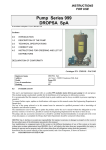
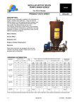
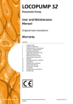
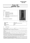
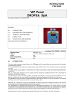
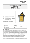
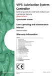
PUMP SERIES 999 User and Maintenance Manual Warranty information TABLE OF CONTENTS 1. 2. 3. 4. 5. 6. 7. 8. 9. 10. 11. 12. 13. 14. 15. 16. 17. 18. INTRODUCTION GENERAL DESCRIPTION PRODUCT-MACHINE IDENTIFICATION TECHNICAL SPECIFICATIONS MACHINE COMPONENTS UNPACKING AND INSTALLING THE MACHINE INSTRUCTIONS FOR USE TROUBLESHOOTING MAINTENANCE PROCEDURE DISPOSAL ORDERING INFORMATION DIMENSIONS HANDLING AND TRANSPORTATION OPERATING HAZARDS PRECAUTIONS WARRANTY INFORMATION DECLARATION OF COMPLIANCE WITH STANDARDS DROPSA LOCATIONS Manufacturer Product Year DropsA SpA PUMP 999 1999 Certification http://www.dropsa.com Manual drawn up in accordance with EC Directive 98/37, Annex I, paragraph 1.7.4 C2021IE– WK 15/06 1. INTRODUCTION This user’s and maintenance manual refers to a series 999 modular motor-driven gear pump for oil and grease. This modular pump is particularly suitable for the distribution of oil and grease in lubrication systems. It is recommended that this manual is carefully kept in good condition and is always available to persons requiring to consult it. To request further copies, updates or clarifications with respect to this manual contact the Engineering Department at Dropsa SpA. The use of the pump referred to in this manual must be entrusted to qualified personnel with a knowledge of hydraulics and electrical systems. The manufacturer reserves the right to update the product and/or the user’s manual without the obligation to revise previous versions. It is however, possible to contact the Engineering Department for the latest revision in use. The pump, and any accessories mounted on it, should be carefully checked immediately on receipt and in the event of any discrepancy or complaint the Dropsa SpA Sales Department should be contacted without delay. DROPSA S.p.A. declines to accept any responsibility for injuries to persons or damage to property in the event of the non-observance of the information presented in this manual. Any modification to component parts of the system or the different destination of use of this system or its parts without prior written authorisation from DROPSA S.p.A. will absolve the latter from any responsibility for injury or damage to persons and/or property and will release them from all obligations arising from the guarantee. Instructions for the correct ordering of the required model, and a list of importers, is shown in Section 4. 2. GENERAL DESCRIPTION The features which distinguish this pump are: high performance; simplicity of construction; modularity. The simplicity of construction guarantees long life, reliability and simplified and reduced maintenance. The modularity of the components allows the system engineer to construct the lubrication unit to meet the specific needs of the lubrication system it is serving. 3. PRODUCT-MACHINE IDENTIFICATION Machine identification yellow label is located on the front side of the reservoir and contains product serial number, input voltage and details of the operating parameters. 4. TECHNICAL SPECIFICATIONS 4.1 Electrical system piston pump Electrical power supply: AC ELECTRIC MOTOR Single phase 220 VAC 50 H2 0.12 KW 3-Phase 220/380 VAC 50 H2 0.18 KW 4 pole Electrical power supply: DC ELECTRIC MOTOR Single phase 24 VDC – 120 W 12 VDC – 100 W 2 4.2 Hydraulic system Connection between the pump and the valve block by steel tubing with connectors. (Only for requested versions) SERIES 999000 ELECTRICALLY MOTOR-DRIVEN PUMP STANDARD LAY OUT LAY OUT WITH QTY 2 PUMP ELEMENTS, BYPASS, PRESSURE GAUGE, FILLING FILTER, HYDRAULIC INVERTER & DELIVERY FILTER 4.3 Other data Class of protection Grade of mechanical protection Operating temperature Operating humidity Preservation temperature Level of continuous sound pressure F IP 55 - 5 - + 40 °C 90 % relative humidity - 20 - + 50 °C < 70 dB(A) 3 5.0 MACHINE COMPONENTS The pump is made up of a series of components: CHARACTERISTICS PUMP 999 Electric piston pump Fixed flow rate pump element Piston diam. 6 mm. Piston diam. 8 mm. 0.20 cc/stroke 0.35 cc/stroke Variable flow rate pump element Piston diam. 6 mm: Piston diam. 8 mm. from 0.028 to 0.20 cc/stroke from 0.05 to 0.35 cc/stroke Maximum pressure - bar (MPa) Tank capacity Characteristics of the mineral lubricant 750 (75) 3 – 5 – 10 - 30 oil: min. 15 CSt grease: max. NLGI 2 5C - + 40 °C Consult Engineering Dept Dropsa Temperature of use For operations outside of this range Variable flow rate model: AC Motor (specify if single or 3 phase) DC Motor Fixed flow rate model: AC Motor (specify if single or 3 phase) 220-380 V 50/60 Hz at 1500 rpm 24V at 2200 rpm 220-380 V 50/60 Hz at 1500 rpm DC Motor 24V at 2200 rpm Insulation Class F 5.1 Minimum level indicator Electro-mechanical type Normally closed at minimum level. Maximum commutable power ISA; maximum commutable voltage 220/250 VAC; a lubricant maximum level and reserve indicator is available on request: fitted with floats and two switches (minimum and zero) 5.2 Pressure gauge (Accessory) Two types of pressure gauge are available: PART N° 299196 291395 PRESSURE RANGE 0 - 500 bar (0 - 50 MPa) 0 - 1000 bar (0 -100 MPa) 5.3 Pressure regulator (Accessory) Three types of regulator (valves) are available to protect the system from overpressures. PART N° 299450 299451 299452 + 4 PRESSURE RANGE 0 - 250 bar (0.25 MPa) 0 - 350 bar (0.35 MPa) 50 - 800 bar (5.80 MPa) WARNING: Pay strict attention to what is indicated on the valves when assembling. Incorrect assembly of the regulator (valve) can result in an overpressure which could prejudice the correct functioning of the pump itself and be dangerous for the user. 5.4 Filling filter (only for the grease version) (Accessory) This removable cartridge filter is recommended to ensure the filling of lubricant which is free from foreign bodies and to avoid the formation of air bubbles. 5.5 Hydraulic inverter (Accessory) PART N° 86240 86199 DESCRIPTION Complete with base mounting plate Inverter only Pressure up to 300 bar. Type of lubricant: oil minimum viscosity 15 cSt – grease maximum consistency NLGI2 5.6 Auxiliary pump element The pumps are supplied with one pump element only, but a second one can be mounted; this would permit the feeding of two lines independently or the combining of the outlets of the two pump elements to obtain a doubling of the flow rate. To obtain the part number of the auxiliary pump element consult the table by utilising the last number off the 999 base pump, or its flow rate specification (at 1500 rpm) and its maximum working pressure. 5.7 Maximum level electrical contact The metal tanks, except those of 3 and 5 litres, can be fitted with electrical maximum level indicators for automatic replenishing of the tank. Tanks for grease: Electrical contact Part N° 299197 Tanks for oil Electrical contact Part N° 291155 6. UNPACKING AND INSTALLING THE PUMP 6.1 Unpacking Once a suitable location has been found to install the unit remove the pump from the packaging. Check the pump has not been damaged during transportation or storage. No particular disposal procedures are necessary, however packing should be disposed of in accordance with regulations that may be in force in your area or state. 6.2 Installing the pump Damage to the power supply cable and housing could result in contact with high voltage (220/380 VAC) live parts and hence be a danger to life: ♦ carefully check the integrity of the power supply cable and the unit before use; ♦ In the event of there being damage to the power supply cable or the unit, DO NOT put the system into service!; ♦ Replace the damaged power supply cable with a new one; ♦ The unit can be opened and repaired ONLY by qualified personnel; ♦ In order to prevent dangers of electric shock due to direct or indirect contact with live parts it is necessary that the electrical power supply line is adequately protected by a suitable differential magneto-thermal circuit breaker with an intervention threshold of 0.03 Ampere and a max. operating time of 1 second. The breaking capacity of the circuit breaker must be ≤ 10 kA and the nominal current In = 4 A. ♦ The connection of the pressure switch mounted directly on the tank must be 24 VAC/DC. ♦ The pump MUST NOT be submersed in fluids or utilised in environments which are particularly aggressive or explosive/inflammable if not prepared for this purpose beforehand by the supplier. ♦ For correct fixing verify the distance between centres shown in the diagram in Section 2. ♦ Use gloves and safety glasses as required in the lubrication oil safety chart; ♦ DO NOT use aggressive lubricants with NBR gaskets and seals; if in doubt consult the Engineering Department of Dropsa SpA, who will provide a chart with the details of recommended oils; ♦ DO NOT ignore dangers to health and observe all hygiene standards; 5 ♦ WARNING! All electrical components must be grounded. This refers to both electrical components and control devices. In this regard ensure that the ground cable is correctly connected. For reasons of safety the ground cable must be approx. 100 mm longer than the phase cables. In the event of accidental detachment of the cable, the ground terminal must be the last to be removed. Action to be taken prior to start up ♦ Verify the integrity of the pump; ♦ Fill the tank with suitable lubricant (min/max indication on the tank); ♦ Verify that the pump is at operating temperature and the tubing free from air bubbles; ♦ Check that the electrical connections have been effected correctly (UNI 64/8, IEC …); + The minimum level indicator is supplied, unless otherwise specified by the customer, with the contact closed for minimum level. Should the user require to use a normally open contact it will be necessary to invert the operating direction of the microswitch. 7. INSTRUCTIONS FOR USE 1. 2. 3. 4. 6 Verify the settings made; Press the start button of the machine to which the 999 series pump is connected; Verify the starting of the pump; Verify the adequate lubrication of the machine (if doubt exists as to the correct functioning consult the Engineering Department of Dropsa SpA to request test procedures). 8. TROUBLESHOOTING DIAGNOSTIC TABLE ANOMALY CAUSE The pump does The tank is empty not deliver lubricant The tank has been filled from above and not through the side connection fitted with a filter. REMEDY Refill the tank with clean lubricant, in accordance with the procedure shown in the Maintenance section. Warning: if the tank has emptied without the minimum level electrical contact having signalled the minimum level, check the contact. Remove the air vent plug B (see fig. on page 6) and run the pump allowing the grease to exit until free from air bubbles. Replace and partly screw in plug B and continue running the pump until grease exits between the threads and the plug and then fully tighten the vent plug. The piston of the pump element assembly is Replace the pump element. seized or the piston return spring is broken The pump does not function because the grease being used is of a consistency greater than NLGI 3 (max. recommenced consistency). Remove the tank from the pump, remove the unsuitable grease and wash out the tank and filter with petrol. Disassemble the pump element and wash out with petrol. Reassemble completely, refill the tank (utilising the side connection fitted with a filter) wit suitable grease and run the pump, ensuring that grease free from air bubbles exits. If necessary, remove the air vent plug B (see fig. on page 6) and proceed as in the previous point. The pump fails to function because it has been run with the tank empty creating an air lock inside the pump itself. Irregular pressure Remove the plug which closes the auxiliary pump element outlet or, where the pump has two elements fitted, remove one of the two pump elements and run the pump until homogeneous grease exits. Replace the plug (or the pump element) and continue running the pump until grease exits free from air bubbles. If necessary, remove the air vent plug B (see fig. on page 6) and proceed as indicated above. Pump element return Disassemble the parts shown in diagram A (see fig. on page 6) valve and seating dirty. and wash them in petrol. Also clean the valve seating. Check the condition of the components and replace if necessary. Pressure regulating Disassemble the parts of the valve shown in the diagram and valve (by-pass) dirty. wash them in petrol. Also clean the valve seating. Check the condition of the components and replace if necessary. Valve Part N° Spring part N° Pressure reg. 299450 299456 0 - 250 Bar 299451 299457 0 - 350 Bar 299452 299458 0 - 800 Bar Before reassembling the valve, check that the ring seal 18818 has not been damaged. 7 ANOMALY CAUSE Irregular flow Screw C, which rate secures the pump element D and return spring E, is loose. REMEDY Remove the pump element assembly from the pump body and completely disassemble it. To reassemble the pump element assembly see the sequence in the diagram. Check all the parts and reassemble after having washed them all in petrol. Warning: put some Loctite type sealant on screw C, which is inserted into pump element D. Hold the pump element between wooden vice clamps to prevent damage to the lapped surface. Adjustable Pump Element Part No. 299041 Ø 6 mm Part No. 299042 Ø 8 mm Fixed Pump Element Part No. 299039 Ø 6 mm Part No. 299040 Ø 8 mm 9. MAINTENANCE PROCEDURE Locate the machine in conditions which facilitate easy access. Utilise individual protection to avoid contact with mineral oil Periodic inspections Periodically it is necessary to check: VERIFICATION The state of lubrication The oil/grease level Cleanliness of the filling and intake filter (where fitted) WORK CYCLE/RUNNING TIME 1000/every 6 months 2000/once a year 500/every 6 months The machine does not require any special tools to carry out checks or maintenance tasks, However, it is recommended that only tools suitable for the tasks and in good condition should be utilised (DPR 547/55) to avoid injury to persons or damage to machine parts. 9.1 Assembly/Disassembly No pump assembly operations are envisaged. For wall mounting ensure adequate space is available (as shown in the installation diagram) to avoid abnormal postures and possible impacts; four fixing holes are provided for wall mounting and three for base fitting. Subsequently it will be necessary, as previously described, to connect the pump to the machine hydraulically and then to connect the control panel. During the disassembly phase ensure the tank is empty. Disconnect the electrical and hydraulic parts. Where the machine is to be scrapped, do not dispose of potentially polluting parts in the environment, following local regulations for their correct disposal. At the time of the machine being scrapped it is necessary to remove and destroy the identification plate and all other relative documents. 8 9.2 Regulation Flow rate (for versions with adjustable flow rates) It is possible to regulate the flow rate by rotating the regulating screw (8 mm hexagonal key) clockwise to decrease and anticlockwise to increase. 9.3 Repairs The following diagnostic table indicates the main anomalies which may be encountered, the probable causes and possible solutions. The anomalies shown are: • the pump fails to deliver lubricant • irregular pressure • irregular flow rate In case of doubts and/or problems which cannot be resolved do not attempt to disassemble parts of the machine but contact the Engineering Department of DROPSA S.p.A. 10. DISPOSAL During maintenance or disposal of the machine care should be taken to properly dispose of environmentally sensitive items such as oils or other lubricants. Refer to local regulations in force in your area. When disposing of this unit, it is important to ensure that the identification label and all the other relative documents are also destroyed. 11. ORDERING INFORMATION 11.1 VERSIONS Type of motor and R.P.M.* A.C. 1500 R.P.M. Adjustable delivery Cm3/min Cu.in./min. Min. Max. Min. Max. 1,4 8,5 ,08 ,6 2,5 17 ,15 1 33 ,30 2 5 Max. Press. bar (psi.) 750 (11000) 400 (5800) 200 (2900) Part No. of Motor Driven Pump 999000 Series Metal Reservoirs Capacity Grease Max. NLGI 3. Oil Viscosity Min. 15 cSt 3Kg. 6.6lbs. 5Kg. 11lb. 10Kg. 22lb. 30Kg. 66lb. 3 Lt. 5 Lt. 10 Lt. 30 Lt. 999234 999214 999224 999204 999244 999264 999274 999254 999236 999216 999226 999206 999246 999266 999276 999256 999232 999212 999222 999202 999242 999262 999272 999252 999334 999314 999324 999304 999344 999364 999374 999354 999336 999316 999326 999306 999346 999366 999376 999356 999332 999312 999322 999302 999342 999362 999372 999352 Fixed delivery A.C. 1500 R.P.M. 8,5 ,6 17 1 33 2 750 (11000) 400 (5800) 200 (2900) R.P.M.* and lubricant deliveries indicated in the table refer to 50Hz. motors. With 60Hz. motors speeds and deliveries are increased by 20%. Complete pumps: Pump Assy. Part No. 999525 999510 999527 999506 999533 999540 Adjustable delivery 3 cm /min. 2,5 ÷ 17 5,0 ÷ 33 5,0 ÷ 33 Fixed delivery 3 cm /min. 17 33 33 Pressure bar 300 * 200 200 Grease Reservoir Kg. 30 5 10 Pump Part. no 999206 999212 999222 Kit part no. 300 200 200 30 10 30 999306 999322 999302 299462 299474 299474 299462 299474 299474 9 11.2 Mounting Kit 999 series pumps can be supplied complete with a kit comprising of: Filling filter– Pressure gauge – Pressure regulating valve and mounting Base. To order the Kit it is necessary to indicate the pressure of the pump, the number of pump elements and the number of outlets. Kit Part N° 299482 299484 299486 299443 299444 299445 299481 299483 299485 N° Pump elements 1 2 2 1 2 2 1 2 2 N° outlets 1 1 2 1 1 2 1 1 2 Pressure 0 -20 MPa 0 - 200 bar 5 - 35 MPa 50 - 350 bar 5 - 70 MPa 50 - 700 bar 12. DIMENSIONS OVERALL DIMENSIONS: D I m 3 Kg. (6.6 lbs.) Trans. Metal A B CØ 10 mm. 300 332 197 In. 11.8 13.07 7.8 mm. 300 468 197 In. 11.8 18.4 7.8 Grease Reservoir 5 Kg. (11 lbs.) Trans. Metal mm. 300 392 197 In. 11.8 15.4 7.8 mm. 300 528 197 In. 11.8 20.8 7.8 10 Kg. (22 lbs.) mm. 423 623 299 In. 16.6 24.5 11.8 30 Kg. (66 lbs.) mm. 453 803 358 In. 17.8 31.6 14.1 3 litres (.8 US gal.) mm. 300 370 197 In. 11.8 14.5 7.8 Oil Reservoir 5 litres 10 litres (1.3 US (2.6 US gal.) gal.) mm. 300 430 197 In. 11.8 16.9 7.8 mm. 423 535 299 In. 16.6 21 11.8 30 litres (8 US gal.) mm. 453 692 358 In. 17.8 27.2 14.1 13. HANDLING AND TRANSPORTATION Prior to shipping, the equipment is carefully packed in cardboard package. During transportation and storage, always maintain the pump the right way up as indicated on the box. On receipt check that package has not been damaged. Then, storage the machine in a dry location. No particular precautions are required except as noted on the package itself. Handling must be effected by at least two persons. ! Lift the unit with taking account of the right way up indicated on the cardboard carton ! The machine components can withstand temperatures, during storage, from -20 to +50°C; however, in order to avoid damage, starting of the machine should occur at a minimum temperature of -5°C. 14. OPERATING HAZARDS 14.1 SAFETY WARNINGS • It is necessary to read and understand the possible hazards and risks involved when using centralized lubrication systems. The operator must fully understand the hazards explained in this manual. • An improper use of centralized lubrication systems may cause damages due to an excessive or inadequate lubrication of the points to which it is connected. • It is always necessary to comply with the accident prevention laws and the environmental regulations in force in the area where the centralized lubrication system is used. Power supply Any type of intervention must not be carried out before unplugging the machine from power supply. Make sure that no one can start it up again during the intervention. All the installed electric and electronic equipment, reservoirs and basic components must be grounded. Flammability The lubricant generally used in lubrication systems is not normally flammable. However, it is advised to avoid contact with extremely hot substances or naked flames. Pressure Prior to any intervention, check the absence of residual pressure in any branch of the lubricant circuit as it may cause oil sprays when disassembling components or fittings. Noise Pump does not produce excessive noise, less than 70 dB(A) . 14.2 LUBRICANTS • It is useful to remember that systems manufactured by Dropsa SpA are designed to be used with lubricants with a maximum grade of NLGI 2 • Use only compatible lubricants with NBR seals • Dropsa SpA supplies system lubricated components with NLGI 2 lubricant. Family description Fluid greases Semi-fluid greases Semi-fluid greases Mild greases Medium greases NLGI grade 000 00 0 1 2 ASTM penetration at +25°C(+77 °F) in 1/10 of mm 445 – 475 400 – 430 355 – 385 310 – 340 265 - 295 This table provides comparative data between NLGI (National Lubricating Grease Institute) and ASTM (American Society for Testing and Materials) data only for the values concerning systems manufactured by Dropsa SpA. For further information on technical data and safety measures, see Product Safety Sheet (Directive 93/112/EEC) related to the type of lubricant selected or supplied by the manufacturer. 11 15. PRECAUTIONS The verification of conformity with the essential safety requirements and regulations of the Machine Directive is effected by means of the compilation of a check list which has been pre-prepared and is contained in the technical file. The lists which are utilised are of three types: • list of dangers (as in EN 414 referring to EN 292) • application of essential safety requirements (Machine Dir. - att. 1, part 1) • electrical safety requirements (EN 60204-1). The following is a list of dangers which have not been fully eliminated but which are considered acceptable: • in the version of the pump without a release it is possible to encounter squirts of oil (for this reason appropriate protective clothing must be worn) • contact with oil -> see the requirements for the use of suitable personal protective clothing • use of unsuitable lubricant -> the characteristics of the fluid are shown on the pump and in the manual (in case of doubt contact the Eng. Dept of Dropsa Spa) • protection against direct and indirect contact must be provided by the user • given the purpose of the pump it must always be functioning; for this reason it is necessary to pay attention to the electrical connections which, in the case of a power failure, the customer’s machine is restarted only by means of a reset, while the lubrication pump is able to restart automatically. • incorrect assembly of the regulator (valve) can result in an over pressure which can prejudice the functioning of the pump itself and create danger for the user. This is avoided by stamping the mounting instructions on the table. INADMISSIBLE FLUIDS Fluid Lubricants with abrasive additives Lubricants with silicone based additives Petrol – solvents – inflammable liquids Corrosive products Water Food substances 12 Danger High wear rate of contacted parts Seizure of the pump Fire – explosion – damage to seals Corrosion of the pump– injury to persons Oxidation of the pump Contamination of the substances themselves 16. WARRANTY INFORMATION All products manufactured and marketed by Dropsa are warranted to be free of defects in material or workmanship for a period of at least 12 months from date of delivery. Extended warranty coverage applies as follows: Complete system installation by Dropsa: 24 Months All other components: 12 months from date of installation; if installed 6 months or more after ship date, warranty shall be maximum of 18 months from ship date. If a fault develops, notify us giving a complete description of the alleged malfunction. Include the part number(s), test record number where available (format xxxxxx-xxxxxx), date of delivery and installation and operating conditions of subject product(s). We will subsequently review this information and, at our option, supply you with either servicing data or shipping instruction and returned materials authorization (RMA) which will have instructions on how to prepare the product for return. Upon prepaid receipt of subject product to an authorized Dropsa Sales & Service location, we will then either repair or replace such product(s), at out option, and if determined to be a warranted defect, we will perform such necessary product repairs or replace such product(s) at our expense. Dropsa reserves to right to charge an administration fee if the product(s) returned are found to be not defective. This limited warranty does not cover any products, damages or injuries resulting from misuse, neglect, normal expected wear, chemically caused corrosion, improper installation or operation contrary to factory recommendation. Nor does it cover equipment that has been modified, tampered with or altered without authorization. Consumables and perishable products are excluded from this or any other warranty. No other extended liabilities are states or implied and this warranty in no event covers incidental or consequential damages, injuries or costs resulting from any such defective product(s). The use of Dropsa product(s) implies the acceptance of our warranty conditions. Modifications to our standard warranty must be in made in writing and approved by Dropsa. 13 17. DECLARATION OF COMPLIANCE WITH CE STANDARDS Manufacturer: DROPSA SpA Company Via Croce, 1 - 20090 Vimodrone (MI), Italy Address +39 02 250791 Telephone states, by the terms of Directive 98/37/CE Allegato I, paragrafo 1.7.4, that: The machine: • • • ∗ Pump 999 Has been designed to be integrated in a machine that complies with the requirements of Directive 98/37/CE. Is compliant with the requirements of Directive 98/37/CE; Is compliant with the requirements of the EMC Directive 89/336/EEC and with Directive 92/31/EEC “Electromagnetic compatibility", as indicated in Directive 95/54/EEC “Measurement of irradiated electromagnetic emissions”. Furthermore, the manufacturer states that the unit can be operated only if the machine on which it is installed has been identified and found compliant with the requirements of Directive 98/37/CE. is manufactured in accordance with the following standards and harmonised technical specifications: EN 12100/1, EN 292/2, EN 50081-2, EN 50082-2, CEI EN 60204-1, EN 1050. Technical Manager Product Manager DROPSA SpA Company Ing. Walter Divisi Name - Vimodrone (MI) - Italy January 1999 Signature 14 Date 18. DISTRIBUTORS Dropsa USA Inc. 50679 Wing Drive Utica, Michigan 48315, USA Tel: (+1) 586-566-1540 Fax: (+1) 586-566-1541 E-mail: [email protected] Dropsa France 23, Av.des.Morillons Z.I. des Doucettes 91140 - Garges Les Gonesse Tel: (+33) 01 39 93 00 33 Fax: (+33) 01 39 86 26 36 E-mail: [email protected] Dropsa (UK) Ltd Unit 6, Egham Business Village, Egham,Surrey,TW20 8RB Tel: (+44) 01784 - 431177 Fax: (+44) 01784 - 438598 E-mail: [email protected] Dropsa do Brazil Rua Sobralia 171 Santo Amaro Sao Paulo, Brazil Tel: (+55) 011-5631-0007 Fax: (+55) 011-5631-9408 E-mail: [email protected] Dropsa S.p.A. Via B. Croce,1 20090 Vimodrone (MI) Italy. Tel: (+39) 02 - 250.79.1 Fax: (+39) 02 - 250.79.767 E-mail: [email protected] (Export) E-mail: [email protected] (National) Polydrop S.A. Av. Fabregada 26 - Pje Est.2 08907 L'Hospitalet de LLobregat Barcelona, Spain Tel: (+34) 93 260 22 50 Fax: (+34) 93 260 22 51 E-mail: [email protected] Dropsa Gmbh Volmerswerther Strasse 80 40221 Dusseldorf 1, Germany Tel: (+49) 0211/39 40 11 Fax:(+49) 0211/39 40 13 E-mail: [email protected] Dropsa Australia Pty. C20/148 Old Pittwater Road Brookvale NSW 2100 Tel: (+61) 299 386 644 Fax: (+61) 299 386 611 E-mail: [email protected] Web site: http://www.dropsa.com - E-mail: [email protected] 15