1
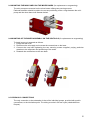
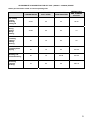
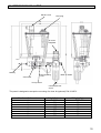
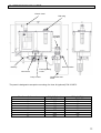
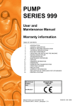
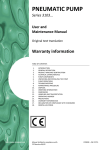
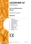
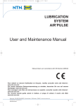
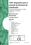
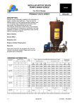
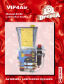
VIP4Air
Minimal Air/Oil
Lubrication System
Automatic Lubrication Systems
The VIP4Air is the most complete and compact
Minimal Air/Oil Lubrication System available today.
Air/Oil Minimal lubrication is a relatively new technology that has
been used successfully to substitute costly Oil Re-circulation and
non environmentally-sound Mist Systems.
It has provided excellent results both in terms of performance and
total system cost.
It is ideal for use on Bearings, High Speed Bearings, Gears and
also in certain circumstances on Guides. It is particularly suited to
Spindle Lubrication.
In the past, excessive oil has been used often only to ensure that
the ‘system is working’. This oil generates heat and has to be
collected away from the lubrication point.
Dropsa has taken the ‘minimal lubrication’ concept one step further
with the VIP4Air that can achieve ultra-low volume oil discharge
and at the same time provide electronic monitoring (using a custom
designed differential flow sensor integrated into the unit). This
allows true minimal lubrication by applying micro-amounts of
lubricants at more frequent intervals whilst giving positive feedback
that oil is correctly being injected and mixed into the air stream.
The VIP4Air System contains all components necessary to
achieve and monitor optimum minimal Air/Oil Lubrication.
N°
Pumps
1
2
3
4
5
6
7
8
VIP4Air 24 V DC
VIP4Air 110 V AC
3135064
3135055
3135067
3135070
3135073
3135076
3135079
3135082
3135065
3135056
3135068
3135071
3135074
3135077
3135080
3135083
Attention: connector not included, to be ordered
separately; connector, p/n 1639115 + cable 2 mt
Technical Characteristics
VIP4Air Lubrication System
24 V DC
110 V AC
Voltage
Power
Air Pressure Inlet
PRODUCT FEATURES :
Output Signal
• 1 – 8 Lubrication Points each with independent monitoring
• 0.005 – 0.030 cm3 (0.0003 – 0.0018 cu.in) of oil per discharge
(standard settings 7-15-30 mm3)(0.0004 – 0.0009 – 0.018 cu.in).
• Tamperproof adjustment ‘rings’ avoids end-user modifications.
• Integrated Differential Flow sensor gives positive feedback of
Air/Oil lubrication.
• Fully Electronic Controls = quick Set-up and interfacing to host.
• Integrated Mixing Air Pressure Transducer provides accurate
and quick setting of Air Pressure on the electronic display, as
well as providing alarms for blocked or broken lubrication lines
via high/low air pressure monitoring.
• Automated Priming Sequence for quick and easy installation.
• Integrated & Compact – Connections are internal to the unit
Operating
Temperature
Humidity
Protection
Lubricants
Air/Oil Minimal Lubrication :
Continuous Air Flow:
Cyclic micro-oil Injection:
Provides Cooling
Reduces friction
Provides Transport Medium
Minimal quantities avoid
‘churning’ and heat generation.
Prevents Contamination and
ingress of water or dirt.
No Excess Oil
Oil Viscosity
Reservoir capacity
10 W
5 ÷ 8 bar
(73.5 ÷ 117.6 psi)
Remote Alarm
relay: max 250 V
1 A NO / NC
-5 ÷ +55 °C
(23 ÷ 131°F)
90% max
IP-44
Mineral Oils
32 ÷ 220 cSt
(150 ÷ 1018 SUS)
1 lt
Elements
Y
X
Z
Depth
1
2
3
4
5
6
7
8
331
359
387
415
443
471
499
527
270
200
125
Frequent lubrication intervals
help thermal stability of system.
Dropsa is a leading international manufacturer of Automatic
Lubrication Systems and can assist with a wide range of technical
and application advice, systems and components. Contact one of
our offices or distributors for more information.
Web site:
http://www.dropsa.com
E-mail:
[email protected]
WK 32/03
C2033PE
ITALIA
Dropsa SpA
t.(+39) 02-250791
f.(+39) 02-25079767
ESPAÑA
Polydrop, S.A.
t.(+34) 93-260-22-50
f.(+34) 93-260-22-51
U.S.A.
Dropsa Corporation
t.(+1) 586-566-1540f.(+1) 586-566-1541
U.K.
Dropsa (UK) Ltd
t.(+44) 01784-431177
f.(+44) 01784-438598
BRAZIL
Dropsa
t.(+55) 011-563-10007
f.(+55) 011-563-19408
AUSTRALIA
Dropsa Australia Ltd.
t.(+61) 02-9938-6644
f.(+61) 02-9938-6611
GERMANY
Dropsa Gmbh
t.(+49) 0211-394-011
f.(+49) 0211-394-013
FRANCE
Dropsa Ame
t.(+33) 01-3993-0033
f.(+33) 01-3986-2636
VIP4Tools
LUBRICATION SYSTEM
User and
Maintenance Manual
Warranty Information
TABLE OF CONTENTS
1.
2.
3.
4.
5.
6.
7.
8.
9.
10.
11.
12.
13.
14.
15.
16.
17.
18.
INTRODUCTION
IDENTIFICATION
GENERAL DESCRIPTION
DESCRIPTION OF COMPONENTS
TECHNICALSPECIFICATION
HANDLING AND TRANSPORT
PRECAUTION IN USE
CONTRAINDICATIONS
INSTALLATION
INSTRUCTIONS FOR USE
MAINTENANCE
DISPOSAL
REPLACEMENT PART LIST
DIMENSIONS VIP 1 LITER
DIMENSIONS VIP 3 LITER
GARANTEE
DECLARATION OF CONFORMITY
DISTRIBUTORS
Manufacturer
Product
Year
DropsA SpA
VIP4Tools
2001
Certification
http://www.dropsa.com
Manual drawn up in accordance with CE
Directive 98/37 Att. I, paragraph 1.7.4
C2040IE - WK 51/02
1. INTRODUCTION
This user’s and maintenance manual refers to VIP4Tools air/oil lubrication system.
This manual should be conserved in such a way that it remains undamaged over time and is readily
available to personnel needing to consult it.
Further copies of this manual, updates or clarifications can be obtained by directly contacting the
Technical Sales Office at Dropsa.
The manufacturer reserves the right to update the product and/or the user’s and maintenance manual
without the obligation to revise previous versions. It is however, possible to contact the Technical
Sales Office for the latest revision in use, or to consult our web site at http://www.dropsa.com.
The use of the equipment referred to in this manual must be entrusted to qualified personnel with a
basic knowledge of mechanics, hydraulics and electrical systems.
It is the responsibility of the installer to use tubing suitable for the system; the use of inadequate
tubing can cause problems with the pump, injury to persons and create pollution.
Loosening of connections can cause serious safety problems; carry out a check before and after
installation and, if necessary retighten them.
Never exceed the maximum working pressure values permitted for the panel and the components
connected to it.
Before any maintenance or cleaning operation disconnect the power supply, close off the air supply
and discharge the pressure from inside the equipment and the tubing connected to it.
Do not subject the panel, the connections, the tubing or parts under pressure to violent impacts;
damaged tubing or connections are dangerous and should be immediately replaced.
After long periods of inactivity check air tightness of all parts subjected to pressure.
Personnel must use personal protection equipment, clothing and tools adequate for the location and
the use of the panel both during its operation and during maintenance operations.
The panel, and any accessories mounted on it, should be carefully checked immediately on receipt
and in the event of any discrepancy or complaint the Dropsa SpA Sales department should be
contacted without delay.
Dropsa SpA declines to accept any responsibility for injuries to persons or damage to property in the
event of the non-observance of the information presented in this manual.
Any modification to component parts of the system or the different destination of use of this system or
its parts without prior written authorization from Dropsa SpA will absolve the latter from any
responsibility for injury to persons and/or damage to property and will release them from all
obligations arising from the guarantee
2. IDENTIFICATION OF THE MACHINE
A yellow plate showing the product code and the basic characteristics is mounted on the front of the
oil tank.
3. GENERAL DESCRIPTION
The VIP4Tools panel is to be utilized for ‘on mandrel’ applications, without controls on the machine,
for the lubrication of tooling and chains.
Designed for high performance at a low cost, it is distinguished by its compactness.
The system comprises a pneumatically controlled mini-pump and the mixer base. The mini-pump can
be manually regulated to cover a wide range of needs (0-30 mm³). The modular design of the system
makes it extremely versatile; up to a maximum of 8 mixer bases can be installed. The system can be
timed by adding the pneumatic impulse generator kit P/N 3132572 or by controlling it from the
machine PLC.
2
4. DESCRIPTION OF COMPONENTS
Central VIP4Tools Unit
The central unit of the lubrication system is composed of the following items:
• a Tank, made of transparent plastic material, compatible with lubricants on the market.
• a System for the regulation of the mixer air
• a modular Subframe
• a Samba type Minimum level indicator,
• an adjustable Mini-pump
1 Liter tank
3 Liter tank
ES:(version complete with timer kit)
3
5. TECHNICAL SPECIFICATIONS
CHARACTERISTIC
VIP4Tools lubrication panel
Air supply pressure
Working temperature
Working humidity
Permitted lubricants
Oil viscosity at working
temperature
Conservation temperature
5 - 8 bar
-5 - +55 °C
90% max
Mineral - synthetic
32 - 320 cSt
-20 - +65 °C
SAMBA LEVEL
Temperature:
Maximum switching power:
Maximum current:
Maximum voltage:
-10°C - +80°C
50W 5V
1A
220 V ac
WARNING: DO NOT supply the machine with voltages or pressures other than those indicated
on the specification plate.
6. HANDLING AND TRANSPORT
Prior to dispatch VIP4Tools lubrication panels are carefully packed in a cardboard carton. During
transportation and storage maintain the equipment the right way up as indicated on the carton.
On receipt, check that the packaging is not damaged and store the equipment in a dry place.
7. PRECAUTIONS IN USE
It is necessary to carefully read the warnings and the risks involved in using the lubrication panel. The
operator must understand the functioning of the unit by studying the user’s manual.
Electric currents
No intervention must be attempted on the equipment without first having disconnected the electrical
power supply (electric level) and ensuring that it cannot be reconnected during the intervention.
All installed equipment, electrical, electronic, tank and base structure, must be connected to the
ground line. (see paragraph 10.7).
Flammability
The oil employed in the lubrication circuit is not normally flammable. It is nonetheless indispensable to
take every precaution against the oil coming into contact with very hot parts or open flames.
Pressure
Prior to any intervention on the equipment ensure that pressure is released from all branches of the
lubrication circuit. Failure to do this could result in oil being discharged under pressure where
connections or components are disassembled (see paragraph 10.6).
Noise
The VIP4Tools lubrication panel does not emit excessive noise, remaining below 70dB(A).
WARNING: before carrying out the replacement of the mini-pumps, empty the tank of
lubricant.
4
AIR CHARACTERISTICS
Characteristic
Pressure at point of connection
Max. quantity of particles in suspension
Max. diameter of particles
Dew point
Max. quantity of oil in suspension
Requirement
Min. 6 Bar
15 mg/Nmc
0.05
2° C
5 mg/Nmc
Whenever not utilizing natural base oils compatible with existing health regulations, it is necessary to
adjust the mixer pressure so as to avoid the formation and dispersion of oil mist into the environment.
The mixing pressure is indicatively between 1 and 2.5 Bar.
8. CONTRAINDICATIONS
The VIP4Tools panel does not have any particular contraindications except for the following points:
• The operator coming into contact with fluid due to breakage/opening of supply tubing.
• The operator must be furnished with suitable personal protection clothing/equipment (part VIII –
626 [Safety at Work legislation]).
• Abnormal posture.
• Take note of the indications shown in paragraph 10.2.
• Contact with oil during filling/maintenance.
• The operator must be furnished with suitable personal protection clothing/equipment (part VIII –
626 [Safety at Work legislation]).
• Use of unsuitable lubricants.
Main inadmissible fluids.
Fluid
Lubricants with abrasive additives
Lubricants with silicon based additives
Petrol – solvents – flammable liquids
Corrosive products
Water
Food substances
Danger
High wear rate of contacted parts
Seizure of the pump
Fire – explosion – damage to seals
Corrosion of the pump– injury to persons
Oxidation of the pump
Contamination of the substances themselves
9. INSTALLATION
9.1 UNPACKING
Once a suitable location has been identified for the installation, open the package and remove
the equipment. Check that the VIP4Tools has not sustained damage during transport and
storage.
The packaging material does not require any special disposal precautions, not being in any
way dangerous or polluting.
9.2 MOUNTING THE VIP4Tools PANEL
Provide adequate space for the installation, leaving a minimum room of 100 mm around the
panel. Mount the VIP4Tools panel at shoulder height to avoid unnatural posture or the
possibility of sustaining impacts. Do not install the VIP4Tools in particularly aggressive or
explosive/flammable environments or on components subject to vibration.
Only use the supplied mounting bracket with N° 2 holes for Ø6 mm bolts.
5
9.3 MOUNTING THE MINI-PUMPS ON THE MIXER BASES (for replacement or augmenting)
The mini-pumps are mounted on the mixer bases utilizing two securing screws.
Particular attention should be paid to the correct positioning of the o-rings between the minipump and the mixer base (see diagram below).
9.4 MOUNTING OF THE MIXER ASSEMBLY ON THE VIP4TOOLS (for replacement or augmenting)
To install a new unit proceed as follows:
1. Empty the tank of oil.
2. Disconnect the air supply and unscrew the connections on the base.
3. Connect the new base tightening the two securing screws supplied, paying particular
attention to the alignment and positioning of the seals.
4. Reattach the connections to the new base.
9.5 HYDRAULIC CONNECTIONS
The only connection to be undertaken is that of the individual pumps, provided with push-in
connections, to the lubrication point. The tubing must be in Ø4 mm nylon (obtainable from
Dropsa).
6
9.6 PNEUMATIC CONNECTIONS
Connect the air input to the push-in connector utilizing Ø6 mm nylon tubing both for the pump
and the mixer, and provide a stop valve to permit shutting off the supply.
9.7 ELECTRICAL CONNECTIONS
The only electrical connection required is that of the Samba level. (see paragraph 6 Technical
Specifications)
N.B.: After all connecting up has been completed ensure the tubing and cables are protected from
impacts and are suitably secured.
10. INSTRUCTIONS FOR USE
10.1 STARTING THE VIP4Tools PANEL
Before using the VIP4Tools panel, it is necessary to carry out some preliminary checks:
- check the integrity of the equipment
- check that the electrical and pneumatic connections have been effected correctly
- vent the residual air from the pump using the vent screw, located at the center of the
securing screws, until lubricant exits (retighten the vent screw without using excessive
force).
- to facilitate the venting, regulate the pumps to maximum flow and operate for some
cycles.
10.2 EXCLUDING LUBRICANT DELIVERY FROM AN INDIVIDUAL PUMP:
-Unscrew (anticlockwise) the red cap at the end of the pump to its stop, so completely blocking
off the delivery.
10.3 REGULATING LUBRICANT DELIVERY FLOW:
Use the red cap to determine the nominal flow of the individual pump.
- Completely unscrew the pump red regulating cap (0 mm³ flow) turn clockwise for 1.5 turns
(min. flow 5 mm³) after which every turn corresponds to an increase in flow of 5 mm³ until
reaching 30 mm³ at the 7th turn. (see table)
FLOW (mm³ / stroke)
30
25
20
15
10
5
0 = no pump delivery
TURNS
6.5
5.5
4.5
3.5
2.5
1.5
Completely unscrewed
7
11. MAINTENANCE
The pump has been designed and constructed so as to reduce maintenance to a minimum.
To simplify maintenance it is recommended that the equipment be mounted in an easily reached
location (see paragraph 10.2).
Periodically check the tubing connections for leaks. Always maintain the equipment in a clean
condition in order that any leaks will be immediately evident.
When necessary replace the oil filling filter P/N 3130139.
Periodically empty the pressure regulator condensate trap by rotating the small red valve located at its
base.
The machine does not require any special tools for carrying out checks and/or maintenance tasks. It
is recommended that suitable tools and personal protection clothing (gloves) are used in accordance
with Legislative Decree 626/94 (Safety at Work legislation), and that they are in good condition (DPR
547/55) in order to avoid injury to persons and damage to the machine.
Ensure that electrical, pneumatic and hydraulic supplies are disconnected before undertaking
any maintenance tasks.
12. DISPOSAL
During the maintenance of the machine, or in the event of its being scrapped, do not discard polluting
components in the environment. Refer to local regulations for their correct disposal. At the time of final
disposal of the machine it is necessary to destroy the identification plate and all other documentation.
13. REPLACEMENT PARTS LIST
VERSIONS
N° Dosers
1
2
3
4
5
6
7
8
1 Liter tank
3135091
3135092
3135093
3135094
3135095
3135096
3135097
3135098
COMPONENTS
PART NUMBER
3130139
1524445
3103116C
5717300
3044338
6770072
20685
1655583
DESCRIPTION
Filter, oil filling
Mixer Base
Mini-pump, pneumatic adjustable
Tube, flexible Ø4
Tank, 1 Liter
Tank, 3 Liter
Filter, reducer
Level, Samba
ACCESSORIES
PART NUMBER
5717300
5717301
3132572
3132574
3132575
1524486
1524487
3226661
3226662
DESCRIPTION
Tube, flexible Ø4
Tube, flexible Ø6
Kit, timer
EV – 24V cc + 39979 + N° 3 53923 + N° 3 16077
EV – 110V ac + 39979 + N° 3 53923 + N° 3 16077
Lubrication nozze 32 mm.
Lubrication nozze 48 mm.
LRT 30 - Oil for steel - 1 L pack
LRT 50 - Oil for aluminium - 1 L pack
3 Liter tank
3135111
3135112
3135113
3135114
3135115
3135116
3135117
3135118
8
APPROXIMATE CONSUMPTION FOR LRT OILS (3226661 – 3226662) USAGE
Grams per lubrication nozzle in 8 hours operating time
ALUMINIUM
LEADED BRASS
LEADED STEEL
SOFT STEEL
ALLOY STEEL
STAINLESS STEEL
REFRACTORY
AND TITANIUM
ALLOYS
Saw cutting
Turning
Shearing
Cutting off
35-40
50
50
50-60
Boring
Drilling
Milling
Slotting
40-50
50
60
70
Threading
Tapping
Planing
Shaving
60
70
80
90
Threading blind
tapping
60
70
80
90-100
Moulding and
standard drawing
60
70
80-90
90-100
Broaching
Toothing
Bending
70
80
90
100/110
9
14. DIMENSIONS VIP 1 LITER
Electric Level
Filler plug
Air mixer
Regulator
Delivery
Flow regulating
screw
Vent screw
Mixer air intake
Pump control
Condensate vent
screw
The panel is designed to accept the mounting of a timer kit (optional) P/N 3132572
Number of elements
1
2
3
4
5
6
7
8
Height A (mm)
363
391
419
447
475
503
531
559
Weight (Kg.)
2.7
3.2
3.7
4.2
4.7
5.2
5.7
6.2
10
15. DIMENSIONS VIP 3 LITER
Electric Level
Filler plug
Air mixer
regulator
Delivery
Mixer air intake
Flow regulating
screw
Vent screw
Pump control
Condensate vent
screw
The panel is designed to accept the mounting of a timer kit (optional) P/N 3132572
Number of elements
1
2
3
4
5
6
7
8
Height A (mm)
365
393
421
449
477
505
533
561
Weight (Kg.)
3.6
4.1
4.6
5.1
5.6
6.1
6.6
7.1
11
16. GUARANTEE
All products manufactured and marketed by Dropsa are warranted to be free of defects in material or
workmanship for a period of at least 12 months from date of delivery. Extended warranty coverage applies as
follows:
Complete system installation by Dropsa: 24 Months
All other components: 12 months from date of installation; if installed 6 months or more after ship date, warranty
shall be maximum of 18 months from ship date.
If a fault develops, notify us giving a complete description of the alleged malfunction. Include the part number(s),
test record number where available (format xxxxxx-xxxxxx), date of delivery and installation and operating
conditions of subject product(s). We will subsequently review this information and, at our option, supply you
with either servicing data or shipping instruction and returned materials authorization (RMA) which will have
instructions on how to prepare the product for return. Upon prepaid receipt of subject product to an authorized
Dropsa Sales & Service location, we will then either repair or replace such product(s), at out option, and if
determined to be a warranted defect, we will perform such necessary product repairs or replace such product(s)
at our expense.
Dropsa reserves to right to charge an administration fee if the product(s) returned are found to be not defective.
This limited warranty does not cover any products, damages or injuries resulting from misuse, neglect, normal
expected wear, chemically caused corrosion, improper installation or operation contrary to factory
recommendation. Nor does it cover equipment that has been modified, tampered with or altered without
authorization.
Consumables and perishable products are excluded from this or any other warranty.
No other extended liabilities are states or implied and this warranty in no event covers incidental or
consequential damages, injuries or costs resulting from any such defective product(s).
The use of Dropsa product(s) implies the acceptance of our warranty conditions. Modifications to our standard
warranty must be in made in writing and approved by Dropsa.
12
17. DECLARATION OF CONFORMITY
Manufacturer:
DROPSA SpA
Company
Via B. Croce, 1 - 20090 Vimodrone (MI), Italy
Address
+39 02 250791
Telephone
It is certified that:
The machine:
VIP4Tools lubrication panel
∗ is manufactured in conformity with the DIRECTIVE OF THE COUNCIL OF THE EUROPEAN
COMMUNITY concerning: the machines (98/37/CE), low voltage (BT 73/23/CEE).
∗ is manufactured in accordance with the following standards and harmonised technical
specifications:
EN 292-1/2, EN 1050, EN 982, EN 11200, EN 60947, EN 894-1/2.
TECHNICAL DIRECTOR
Product manager
W. Divisi
Name
DROPSA SpA
Company
November 2001
Signature
Date
13
18. DISTRIBUTORS
N.B.: From this manual the only copy valid is the one with the later WK (number of week/year) shown on the front page
DropsA
Dropsa Corporation
50679 Wing Drive
Utica, Michigan 48315, USA
Tel: (+1) 810-566-1540
Fax: (+1) 810-566-1541
E-mail: [email protected]
Dropsa Ame (Industrie)
23, Av.des.Morillons
Z.IND. des Doucettes
95140 - Garges Les Gonesse
Tel: (+33) 1-3993-003
Fax: (+33) 1-3986-2636
E-mail: [email protected]
Dropsa (UK) Ltd
Unit 6, Egham Business Village,
Egham, Surrey, TW20 8RB
Tel: (+44) 01784 - 431177
Fax: (+44) 01784 - 438598
E-mail: [email protected]
Dropsa do Brazil
Rua Sobralia 175 Santo Amaro,
Sao Paulo, Brazil
Tel: (+55) 11 56310007
Fax: (+55) 11 56319408
E-mail: [email protected]
Dropsa S.p.A.
Via B. Croce, 1
20090 Vimodrone (MI) Italy.
Tel: (+39) 02 - 250.79.1
Fax: (+39) 02 - 250.79.767
E-mail: [email protected] (Export)
E-mail: [email protected] (National)
Poly Dropsa S.A.
Av. Fabregada 26 - Pje Est.2
08907 L'Hospitalet de LLobregat
Barcelona
Tel: (+34) 9326-022-50
Fax: (+34) 9326-022-51
E-mail: [email protected]
Dropsa Gmbh
Volmerswerther Strasse 80
40221 Dusseldorf 1, Deutschland
Tel: (+49) 0211-394-011
Fax:(+49) 0211-394-013
E-mail: [email protected]
Dropsa Australia Pty.
C20/148 Old Pittwater Road
Brookvale
NSW 2100
Tel: (+61) 2 9938-66-44
Fax: (+61) 2 9938-66-11
E-mail: [email protected]
Web site: http://www.dropsa.com - E-mail: [email protected]
14