1
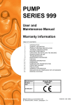
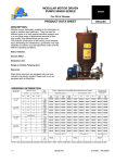
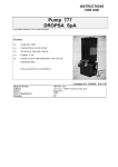
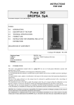
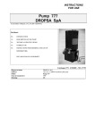
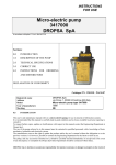
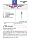
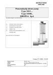
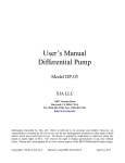
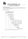
INSTRUCTIONS
FOR USE
Pump Series 999
DROPSA SpA
In accordance with point 1.7.4, to I, Dir 98/37 CE
Sections:
0.0
INTRODUCTION
1.0
DESCRIPTION OF THE PUMP
2.0
TECHNICAL SPECIFICATIONS
3.0
CORRECT USE
4.0
INSTRUCTIONS FOR ORDERING AND LIST OF
DISTRIBUTORS
DECLARATION OF CONFORMITY
Catalogue P/N C2021IE - Wk 23/02
Registered name
Address
Model
Year of manufacture
Marking
0.0
DROPSA SpA
via Croce 1, 20090 Vimodrone (MI), Italy
Pump 999
1999
CE
INTRODUCTION
This user’s and maintenance manual refers to a series 999 modular motor-driven gear pump for oil and grease.
This modular pump is particularly suitable for the distribution of oil and grease in lubrication systems.
It is recommended that this manual is carefully kept in good condition and is always available to persons requiring to
consult it.
To request further copies, updates or clarifications with respect to this manual contact the Engineering Department at
Dropsa SpA.
The use of the pump referred to in this manual must be entrusted to qualified personnel with a knowledge of
hydraulics and electrical systems.
The manufacturer reserves the right to update the product and/or the user’s manual without the obligation to revise
previous versions. It is however, possible to contact the Engineering Department for the latest revision in use.
The pump, and any accessories mounted on it, should be carefully checked immediately on receipt and in the event
of any discrepancy or complaint the Dropsa SpA Sales Department should be contacted without delay.
DROPSA S.p.A. declines to accept any responsibility for injuries to persons or damage to property in the event of
the non-observance of the information presented in this manual.
Any modification to component parts of the system or the different destination of use of this system or its parts
without prior written authorisation from DROPSA S.p.A. will absolve the latter from any responsibility for injury or
damage to persons and/or property and will release them from all obligations arising from the guarantee.
Instructions for the correct ordering of the required model, and a list of importers, is shown in Section 4.
1.0
DESCRIPTION OF THE PUMP
The features which distinguish this pump are:
high performance;
simplicity of construction;
modularity.
The simplicity of construction guarantees long life, reliability and simplified and reduced maintenance. The
modularity of the components allows the system engineer to construct the lubrication unit to meet the specific needs
of the lubrication system it is serving.
The pump is made up of a series of components:
CHARACTERISTICS
PUMP 999
Electric piston pump
Fixed flow rate pump element
Piston diam. 6 mm.
Piston diam. 8 mm.
0.20 cc/stroke
0.35 cc/stroke
Variable flow rate pump element
Piston diam. 6 mm:
Piston diam. 8 mm.
from 0.028 to 0.20 cc/stroke
from 0.05 to 0.35 cc/stroke
Maximum pressure - bar
(MPa)
Tank capacity
750
(75)
3 – 5 – 10 - 30
Characteristics of the mineral
lubricant
oil:
grease:
min. 15 CSt
max. NLGI 2
- 5C - + 40 °C
Consult Engineering Dept
Dropsa
Temperature of use
For operations outside of this range
1.1
Variable flow rate model:
AC Motor
(specify if single or 3 phase)
220-380 V 50/60 Hz
at 1500 rpm
DC Motor
24V at 2200 rpm
Fixed flow rate model:
AC Motor
(specify if single or 3 phase)
220-380 V 50/60 Hz at 1500 rpm
DC Motor
24V at 2200 rpm
Insulation
Class F
Minimum level indicator
Electro-mechanical type
Normally closed at minimum level. Maximum commutable power ISA; maximum commutable voltage 220/250
VAC; a lubricant maximum level and reserve indicator is available on request: fitted with floats and two switches
(minimum and zero)
1.2
Pressure gauge (Accessory)
C2021IE - Pump 999 -
23/02
Page 2 of 11
Two types of pressure gauge are available:
PART N°
299196
291395
1.3
PRESSURE RANGE
0 - 500 bar (0 - 50 MPa)
0 - 1000 bar (0 -100 MPa)
Pressure regulator (Accessory)
Three types of regulator (valves) are available to protect the system from overpressures.
PART N°
299450
299451
299452
☞
1.4
PRESSURE RANGE
0 - 250 bar (0.25 MPa)
0 - 350 bar (0.35 MPa)
50 - 800 bar (5.80 MPa)
WARNING:
Pay strict attention to what is indicated on the valves when assembling.
Incorrect assembly of the regulator (valve) can result in an overpressure which could prejudice the correct
functioning of the pump itself and be dangerous for the user.
Filling filter (only for the grease version) (Accessory)
This removable cartridge filter is recommended to ensure the filling of lubricant which is free from foreign bodies
and to avoid the formation of air bubbles.
1.5
Hydraulic inverter (Accessory)
PART N°
86240
86199
DESCRIPTION
Complete with base mounting plate
Inverter only
Pressure up to 300 bar.
Type of lubricant: oil minimum viscosity 15 cSt – grease maximum consistency NLGI2
1.6
Auxiliary pump element
The pumps are supplied with one pump element only, but a second one can be mounted; this would permit the
feeding of two lines independently or the combining of the outlets of the two pump elements to obtain a doubling of
the flow rate.
To obtain the part number of the auxiliary pump element consult the table by utilising the last number off the 999
base pump, or its flow rate specification (at 1500 rpm) and its maximum working pressure.
1.7
Maximum level electrical contact
The metal tanks, except those of 3 and 5 litres, can be fitted with electrical maximum level indicators for
automatic replenishing of the tank.
Tanks for grease:
Electrical contact Part N° 299197
Tanks for oil
Electrical contact Part N° 291155
2.0
TECHNICAL SPECIFICATIONS
C2021IE - Pump 999 -
23/02
Page 3 of 11
2.1
Fixing and overall dimensions
DIMENSIONS IN mm
WALL FITTING
BASE FITTING
Dimensions
in mm
TANKS FOR GREASE
Transparen
t
Metal
Transparent
C2021IE - Pump 999 -
Metal
TANKS FOR OIL (METAL)
Metal
23/02
Metal
3 litres
5 litres
10 litres
Page 4 of 11
30 litres
2.2
Electrical system – Technical Data
piston pump
Electrical power supply:
AC ELECTRIC MOTOR
Single phase 220 VAC 50 H2 0.12 KW
3-Phase
220/380 VAC 50 H2 0.18 KW 4 pole
Electrical power supply:
DC ELECTRIC MOTOR
Single phase 24 VDC – 120 W
12 VDC – 100 W
2.3
Hydraulic system – Technical Data
Connection between the pump and the valve block by steel tubing with connectors. (Only for requested versions)
SERIES 999000 ELECTRICALLY
MOTOR-DRIVEN PUMP
LAY OUT WITH QTY 2
PUMP ELEMENTS, BYPASS, PRESSURE GAUGE,
FILLING FILTER,
HYDRAULIC INVERTER &
DELIVERY FILTER
STANDARD LAY OUT
2.4
Other data
Class of protection
Grade of mechanical protection
Operating temperature
Operating humidity
Preservation temperature
Level of continuous sound pressure
C2021IE - Pump 999 -
F
IP 55
- 5 - + 40 °C
90 % relative humidity
- 20 - + 50 °C
< 70 dB(A)
23/02
Page 5 of 11
3.0
CORRECT USE
3.1
Putting into service
Damage to the power supply cable and housing could result in contact with high voltage (220/380 VAC) live parts
and hence be a danger to life:
♦ carefully check the integrity of the power supply cable and the unit before use;
♦ In the event of there being damage to the power supply cable or the unit, DO NOT put the system into service!;
♦ Replace the damaged power supply cable with a new one;
♦ The unit can be opened and repaired ONLY by qualified personnel;
♦ In order to prevent dangers of electric shock due to direct or indirect contact with live parts it is necessary that
the electrical power supply line is adequately protected by a suitable differential magneto-thermal circuit breaker
with an intervention threshold of 0.03 Ampere and a max. operating time of 1 second.
The breaking capacity of the circuit breaker must be ≤ 10 kA and the nominal current In = 6 A.
♦ The connection of the pressure switch mounted directly on the tank must be 24 VAC/DC.
♦ The pump MUST NOT be submersed in fluids or utilised in environments which are particularly aggressive or
explosive/inflammable if not prepared for this purpose beforehand by the supplier.
♦ For correct fixing verify the distance between centres shown in the diagram in Section 2.
♦ Use gloves and safety glasses as required in the lubrication oil safety chart;
♦ DO NOT use aggressive lubricants with NBR gaskets and seals; if in doubt consult the Engineering Department
of Dropsa SpA, who will provide a chart with the details of recommended oils;
♦ DO NOT ignore dangers to health and observe all hygiene standards;
♦ WARNING! All electrical components must be grounded. This refers to both electrical components and control
devices. In this regard ensure that the ground cable is correctly connected. For reasons of safety the ground cable
must be approx. 100 mm longer than the phase cables. In the event of accidental detachment of the cable, the
ground terminal must be the last to be removed.
Action to be taken prior to start up
♦ Verify the integrity of the pump;
♦ Fill the tank with suitable lubricant (min/max indication on the tank);
♦ Verify that the pump is at operating temperature and the tubing free from air bubbles;
♦ Check that the electrical connections have been effected correctly (UNI 64/8, IEC …);
☞
The minimum level indicator is supplied, unless otherwise specified by the customer, with the contact
closed for minimum level. Should the user require to use a normally open contact it will be necessary to
invert the operating direction of the microswitch.
3.2
Use
1.
2.
3.
4.
3.3
Verify the settings made;
Press the start button of the machine to which the 999 series pump is connected;
Verify the starting of the pump;
Verify the adequate lubrication of the machine (if doubt exists as to the correct functioning consult the
Engineering Department of Dropsa SpA to request test procedures).
Transport and storage
Transport and storage is effected in a cardboard package.
No particular precautions are required except as noted on the package itself.
Handling must be effected by at least two persons.
!
Lift the unit with taking account of the right way up indicated on the cardboard carton
!
The machine components can withstand temperatures, during storage, from -20 to +50°C; however, in
order to avoid damage, starting of the machine should occur at a minimum temperature of -5°C.
C2021IE - Pump 999 -
23/02
Page 6 of 11
3.4
Assembly/Disassembly
No pump assembly operations are envisaged.
For wall mounting ensure adequate space is available (as shown in the installation diagram) to avoid abnormal
postures and possible impacts; four fixing holes are provided for wall mounting and three for base fitting.
Subsequently it will be necessary, as previously described, to connect the pump to the machine hydraulically and
then to connect the control panel.
During the disassembly phase ensure the tank is empty.
Disconnect the electrical and hydraulic parts.
Where the machine is to be scrapped, do not dispose of potentially polluting parts in the environment, following
local regulations for their correct disposal.
At the time of the machine being scrapped it is necessary to remove and destroy the identification plate and all other
relative documents.
3.5
Regulation
Flow rate (for versions with adjustable flow rates)
It is possible to regulate the flow rate by rotating the regulating screw (8 mm hexagonal key) clockwise to decrease
and anticlockwise to increase.
3.6
Maintenance
!
Locate the machine in conditions which facilitate easy access.
Utilise individual protection to avoid contact with mineral oil
Periodic inspections
Periodically it is necessary to check:
VERIFICATION
The state of lubrication
The oil/grease level
Cleanliness of the filling and intake filter (where
fitted)
WORK CYCLE/RUNNING TIME
1000/every 6 months
2000/once a year
500/every 6 months
The machine does not require any special tools to carry out checks or maintenance tasks, However, it is
recommended that only tools suitable for the tasks and in good condition should be utilised (DPR 547/55) to avoid
injury to persons or damage to machine parts.
3.7
Repairs
The following diagnostic table indicates the main anomalies which may be encountered, the probable causes and
possible solutions.
The anomalies shown are:
• the pump fails to deliver lubricant
• irregular pressure
• irregular flow rate
In case of doubts and/or problems which cannot be resolved do not attempt to disassemble parts of the machine but
contact the Engineering Department of DROPSA S.p.A.
C2021IE - Pump 999 -
23/02
Page 7 of 11
DIAGNOSTIC TABLE
ANOMALY
CAUSE
REMEDY
Refill the tank with clean lubricant, in accordance with the procedure
shown in the Maintenance section.
Warning: if the tank has emptied without the minimum level electrical
contact having signalled the minimum level, check the contact.
The pump does not The tank is empty
deliver lubricant
The tank has been filled
from above and not through
the side connection fitted
with a filter.
Remove the air vent plug B (see fig. on page 6) and run the pump allowing
the grease to exit until free from air bubbles. Replace and partly screw in
plug B and continue running the pump until grease exits between the
threads and the plug and then fully tighten the vent plug.
The piston of the pump Replace the pump element.
element assembly is seized
or the piston return spring is
broken
The pump does not function
because the grease being
used is of a consistency
greater than NLGI 3 (max.
recommenced consistency).
Remove the tank from the pump, remove the unsuitable grease and wash
out the tank and filter with petrol.
Disassemble the pump element and wash out with petrol. Reassemble
completely, refill the tank (utilising the side connection fitted with a filter)
wit suitable grease and run the pump, ensuring that grease free from air
bubbles exits. If necessary, remove the air vent plug B (see fig. on page 6)
and proceed as in the previous point.
The pump fails to function
because it has been run with
the tank empty creating an
air lock inside the pump
itself.
Irregular pressure
Remove the plug which closes the auxiliary pump element outlet or, where
the pump has two elements fitted, remove one of the two pump elements
and run the pump until homogeneous grease exits.
Replace the plug (or the pump element) and continue running the pump
until grease exits free from air bubbles. If necessary, remove the air vent
plug B (see fig. on page 6) and proceed as indicated above.
Pump element return valve Disassemble the parts shown in diagram A (see fig. on page 6) and wash
them in petrol. Also clean the valve seating. Check the condition of the
and seating dirty.
components and replace if necessary.
Pressure regulating
(by-pass) dirty.
Irregular flow rate
valve Disassemble the parts of the valve shown in the diagram and wash them in
petrol. Also clean the valve seating.
Check the condition of the components and replace if necessary.
Valve Part N°
Spring part N°
Pressure reg.
299450
299456
0 - 250 Bar
299451
299457
0 - 350 Bar
299452
299458
0 - 800 Bar
Before reassembling the valve, check that the ring seal 18818 has not been
damaged.
Screw C, which secures the Remove the pump element assembly from the pump body and completely
pump element D and return disassemble it.
To reassemble the pump element assembly see the sequence in the diagram.
spring E, is loose.
Check all the parts and reassemble after having washed them all in petrol.
Warning: put some Loctite type sealant on screw C, which is inserted into
pump element D. Hold the pump element between wooden vice clamps to
prevent damage to the lapped surface.
C2021IE - Pump 999 -
23/02
Page 8 of 11
3.8
Dangers present in use
The verification of conformity with the essential safety requirements and regulations of the Machine Directive is
effected by means of the compilation of a check list which has been pre-prepared and is contained in the technical
file.
The lists which are utilised are of three types:
•
list of dangers (as in EN 414 referring to EN 292)
•
application of essential safety requirements (Machine Dir. - att. 1, part 1)
•
electrical safety requirements (EN 60204-1).
The following is a list of dangers which have not been fully eliminated but which are considered acceptable:
♦
in the version of the pump without a release it is possible to encounter squirts of oil (for this reason
appropriate protective clothing must be worn)
♦
contact with oil -> see the requirements for the use of suitable personal protective clothing
♦
use of unsuitable lubricant -> the characteristics of the fluid are shown on the pump and in the manual
(in case of doubt contact the Eng. Dept of Dropsa Spa)
♦
protection against direct and indirect contact must be provided by the user
♦
given the purpose of the pump it must always be functioning; for this reason it is necessary to pay
attention to the electrical connections which, in the case of a power failure, the customer’s machine is
restarted only by means of a reset, while the lubrication pump is able to restart automatically.
♦
incorrect assembly of the regulator (valve) can result in an over pressure which can prejudice the
functioning of the pump itself and create danger for the user. This is avoided by stamping the mounting
instructions on the table.
INADMISSIBLE FLUIDS
Fluid
Lubricants with abrasive additives
Lubricants with silicone based additives
Petrol – solvents – inflammable liquids
Corrosive products
Water
Food substances
4.0
Danger
High wear rate of contacted parts
Seizure of the pump
Fire – explosion – damage to seals
Corrosion of the pump– injury to persons
Oxidation of the pump
Contamination of the substances themselves
INSTRUCTIONS FOR ORDERING AND LIST OF DISTRIBUTORS
VERSIONS
Type of
motor and
rpm
AC
1500 rpm
DC 24 V
2200 rpm
AC
1500 rpm
DC 24 V
2200 rpm
Adjustable
flow rate
cm³/min
Pressure
max.
SERIES 999 ELECTRIC MOTOR DRIVEN PUMP PART NUMBERS
TANK IN METAL
min
max
1.4
9.5
2.5
17
5
33
2
14.5
3.6
25.5
7.2
51
Fixed flow
rate
9.5
17
33
14.5
25.5
51
bar
750
400
200
750
400
200
MPa
75
40
20
75
40
20
3 Kg
999234
999236
999232
999634
999636
999632
750
400
200
750
400
200
75
40
20
75
40
20
999334
999336
999332
999734
999736
999732
14.5
350
30
999380
GREASE MAX NLGI 3
5 Kg
10 Kg
999214
999224
999216
999226
999212
999222
999614
999624
999616
999626
999612
999622
999314
999316
999312
999395
999712
999713
999324
999326
999322
999724
999726
999722
30 Kg
999204
999206
999202
999604
999604
999602
3 litres
999244
999246
999242
999644
999646
999642
999304
999306
999302
999704
999706
999702
999344
999346
999342
999744
999746
999742
GREASE MAX NLGI 0
DC 12 V
2200 rpm
OLIO VISCOSITY MIN 15 cSt
5 litres
10 litres
30 litres
999264
999274
999254
999266
999276
999256
999262
999272
999252
999664
999674
999654
999666
999676
999656
999662
999672
999652
999364
999366
999362
999764
999766
999762
999374
999376
999372
999774
999776
999772
999354
999356
999352
999754
999756
999752
OIL VISCOSITY MIN 15 cSt
999390
TRANSPARENT
TANKS
GREASE NLGI 0
3 Kg
5 Kg
999414
999424
999416
999426
999412
999428
999684
999694
999686
999696
999682
999698
999514
999524
999516
999526
999512
999522
999784
999794
999786
999796
999782
999792
GREASE
MAX NLGI 0
999385
Rpm and flow rates shown in the table refer to AC motors with 50 Hz frequency. With 60 Hz, the speed of the motor
and the flow rate will increase by 20%. Always specify at time of ordering: voltage – current (3-Phase or Single
C2021IE - Pump 999 -
23/02
Page 9 of 11
phase) – Frequency.
4.1
Mounting Kit
999 series pumps can be supplied complete with a kit comprising of:
Filling filter– Pressure gauge – Pressure regulating valve and mounting Base.
To order the Kit it is necessary to indicate the pressure of the pump, the number of pump elements and the number of
outlets.
Kit Part N°
299482
299484
299486
299443
299444
299445
299481
299483
299485
C2021IE - Pump 999 -
N° Pump elements
1
2
2
1
2
2
1
2
2
23/02
N° outlets
1
1
2
1
1
2
1
1
2
Pressure
0 -20 MPa
0 - 200 bar
5 - 35 MPa
50 - 350 bar
5 - 70 MPa
50 - 700 bar
Page 10 of 11
CE Declaration Of Conformity
Manufacturer:
DROPSA SpA
Company
Via Croce, 1 - 20090 Vimodrone (MI), Italy
Address
+39 02 250791
Telephone
It is certified that:
The machine:
Pump 999
∗ is manufactured in conformity with the DIRECTIVE OF THE COUNCIL OF THE EUROPEAN COMMUNITY
concerning the harmonisation of member states legislation relative to machines (98/37 CE + 91/368/CEE), EMC
(89/336/CEE) and BT (73/23/CEE) and relative amendments.
∗ is manufactured in accordance with the following standards and harmonised technical specifications:
EN 292/1, EN 292/2, EN 50081-2, EN 50082-2, CEI EN 60204-1, EN 1050.
Technical Manager
Product Manager
DROPSA SpA
Company
Ing. Walter Divisi
Name
- Vimodrone (MI) - Italy
January 1999
Date
Signature
DROPSA SPA DISTRIBUTORS
ITALY
Dropsa SpA
t.(+39) 02-250791
f.(+39) 02-25079767
U.S.A.
Dropsa Corporation
t.(+1) 586-566-1540
f.(+1) 586-566-1541
BRAZIL
Dropsa
t.(+55) 011-563-10007
f.(+55) 011-563-19408
AUSTRALIA
Dropsa Australia Ltd.
t.(+61) 02-9938-6644
f.(+61) 02-9938-6611
SPAIN
Polydrop, S.A.
t.(+34) 93-260-22-50
f.(+34) 93-260-22-51
U.K.
Dropsa (UK) Ltd
t.(+44) 01784-431177
f.(+44) 01784-438598
GERMANY
Dropsa Gmbh
t.(+49) 0211-394-011
f.(+49) 0211-394-013
FRANCE
Dropsa Ame
t.(+33) 01-3993-0033
f.(+33) 01-3986-2636
C2021IE - Pump 999 -
23/02
Page 11 of 11