1
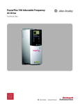
PowerFlex 700 Adjustable Frequency AC Drive
Space Saving Hardware Features
• Integral EMC Filtering plus built-in DC bus choke common mode cores and common mode capacitors provides a
compact, all-in-one package solution for meeting EMC requirements, including CE in Europe. Frames 0…6 only
(Frames 7…10 meet CE when installed per recommendations).
• Internal Communications allow the user to integrate the drive into the manufacturing process. Status indicators for
all internal communication options are visible on the cover for easy setup and monitoring of drive communications.
Users can easily manage information from shop floor to top floor and seamlessly integrate their complete system as
they control, configure and collect data.
• Integral Dynamic Brake Transistor delivers a cost effective means of switching regenerative energy without costly
external chopper circuits. These internal transistors are available in power ratings from 0.5 to 200 Hp.
• Internal Dynamic Brake Resistor (up to 25 Hp) requires no extra panel space, and supplies a large amount of
braking torque for short periods.
Easy to Use Human Interface Tools
The PowerFlex 7-Class AC drives provide common Human Interface tools that are familiar and easy to use. These include
the LCD Human Interface modules and PC-based configuration tools.
• LCD Human Interface modules provide:
– Large and easy to read 7 line x 21 character backlit display
– Variety of languages (English, French, German, Italian, Spanish, Portuguese, Dutch)
– Alternate function keys for shortcuts to common tasks
– “Calculator-like” number pad for fast and easy data entry (Full Numeric version only)
– Control keys for local start, stop, speed, and direction
– Remote versions for panel mount application
Outstanding Control and Performance
Closed Loop Performance
3.0
Multiple motor control algorithms allow performance matched to the
application need:
Torque (Per-Unit)
2.5
2.0
1.5
1.0
0.5
• Volts/Hertz for simple Fan and Pump applications.
0.0
-2
0
2
The PowerFlex 700 drive's Vector Control uses Allen-Bradley's patented Force™
Technology which provides excellent low-speed performance - whether it is
operated with or without feedback. While this industry-leading control
provides the highest level of drive performance, it is as easy to use as any general
purpose drive available.
6
8
10
12
Open Loop Performance
3.0
2.5
Torque (Per-Unit)
• Vector for outstanding torque regulation and excellent low speed/zero
speed performance (w/Vector Control cassette).
4
Frequency (HZ)
• Sensorless Vector for high torque production over a wide speed range.
2.0
1.5
1.0
0.5
0.0
0
2
4
6
8
10
12
Frequency (HZ)
Rockwell Automation Publication 20B-TD001H-EN-P - July 2014
Artisan Technology Group - Quality Instrumentation ... Guaranteed | (888) 88-SOURCE | www.artisantg.com
3