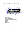
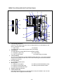
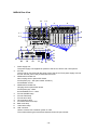
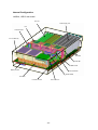
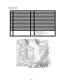
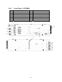
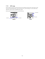
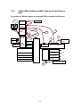
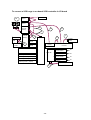
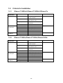
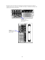
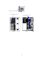
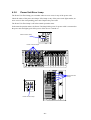
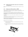
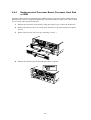
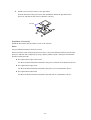
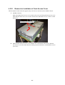
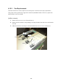
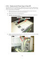
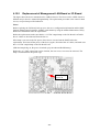
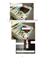
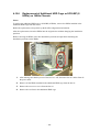
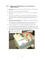
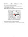
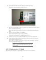
Download 77 A7 16EL 00

Transcript
Service Guide
Hardware: DPS7000/XTA
REFERENCE
77 A7 16EL 00
DPS7000/XTA
NOVASCALE 7000
DPS7000
XTAx5 - 140Rd-4
DPS7000/XTA
NOVASCALE 7000
DPS7000/XTAx5-140Rd-4
Service Guide
Hardware: DPS7000/XTA
January 2006
BULL CEDOC
357 AVENUE PATTON
B.P.20845
49008 ANGERS CEDEX 01
FRANCE
REFERENCE
77 A7 16EL 00
The following copyright notice protects this book under Copyright laws which prohibit such actions as, but not
limited to, copying, distributing, modifying, and making derivative works.
Copyright
Bull SAS 2006
Printed in France
Suggestions and criticisms concerning the form, content, and presentation of this
book are invited. A form is provided at the end of this book for this purpose.
To order additional copies of this book or other Bull Technical Publications, you
are invited to use the Ordering Form also provided at the end of this book.
Trademarks and Acknowledgements
We acknowledge the right of proprietors of trademarks mentioned in this book.
Intel® and Itanium® are registered trademarks of Intel Corporation.
Windows® and Microsoft® software are registered trademarks of Microsoft Corporation.
UNIX® is a registered trademark in the United States of America and other countries licensed exclusively through
the Open Group.
Linux® is a registered trademark of Linus Torvalds.
The information in this document is subject to change without notice. Bull will not be liable for errors contained
herein, or for incidental or consequential damages in connection with the use of this material.
Safety Notes
This section provides notes on using the server safely.
SAFETY INDICATIONS
To ensure proper and safe maintenance of the server, handle the server according to the direction
of the Maintenance Guide.
The Maintenance Guide describes possible dangers in use of the server, the dangers you
encounter if you do not observe the instructions, and the ways to avoid the dangers.
Warning labels are attached to components with possible danger or their vicinity in the server
when operating the server.
In the Maintenance Guide and the warning labels, "WARNING" and "CAUTION" are used as the
terms indicating hazardous levels. The terms are defined to have the following meanings.
WARNING
Indicates the presence of a hazard that may result in death or serious
personal injury.
CAUTION
Indicates the presence of a hazard that may cause minor personal injury,
including burns, or property damage.
Precautions and notices against hazards are presented with one of the following three symbols.
The individual symbols are defined as follows:
This symbol indicates the presence of a hazard.
An image in the symbol illustrates the hazard type. (Attention)
This symbol indicates prohibited actions. An image in the symbol illustrates a
particular prohibited action. (Prohibited Action)
This symbol indicates mandatory actions. An image in the symbol illustrates a
mandatory action to avoid a particular hazard. (Mandatory Action)
-i-
SYMBOLS USED IN THIS GUIDE AND WARNING LABELS
Attentions
Indicates that improper use may cause an electric shock.
Indicates that improper use may cause personal injury.
Indicates that improper use may cause fingers to be caught.
Indicates that improper use may cause fumes or fire.
Indicates a general notice or warning that cannot be specifically identified.
Prohibited Actions
Indicates a general prohibited action that cannot be specifically identified.
Do not disassemble, repair, or modify the server. Otherwise, an electric shock or fire
may be caused.
Mandatory Action
Unplug the power cord of the server. Otherwise, an electric shock or fire may be
caused.
Indicates a mandatory action that cannot be specifically identified. Make sure to follow
the instruction.
- ii -
Safety Notes
This section provides notes on using the server safely. Read this section carefully to ensure proper
and safe use of the server. For symbols, see "SAFETY INDICATIONS" provided earlier.
General
WARNING
Do not use the server for services where critical high availability may directly affect
human lives.
The server is not intended to be used with or control facilities or devices concerning
human lives, including medical devices, nuclear facilities and devices, aeronautics
and space devices, transportation facilities and devices; and facilities and devices
requiring high reliability. The manufacturer assumes no liability for any accident
resulting in personal injury, death, or property damage if the server has been used in
the above conditions.
Do not use the server in any unapproved place.
Install the server on a standard EIA 19-inch rack cabinet.
Do not install the rack containing the server in a place inappropriate to the rack
installation environment.
Failure to follow these instructions may cause some bad influences to be imposed
on the server and other systems installed on the rack and also a fire or personal
injury due to falling of the rack may occur.
For the detailed explanation on the place where the server should be installed and
the earthquake-resistant construction for the rack, refer to the manual attached to
the rack.
Always install the server on a rack conforming to the relevant standard.
Install the server on a rack conforming to the EIA standard for the server to be used.
Do not use the server with installed on any other rack than standard EIA 19-inch
rack or without the installation on a proper rack. Failure to follow these instructions
may cause the server to operate incorrectly and/or personal injury or damages of
surrounding devices to occur.
Do not use the server if any smoke, odor, or noise is present.
If smoke, odor, or noise is present, immediately turn off the POWER switch and
disconnect the power plug from the outlet. Using the server in such conditions may
cause a fire.
Keep needles or metal objects away from the server.
Do not insert needles or metal objects into ventilation holes in the server or
openings in the floppy disk or CD-ROM drive. Doing so may cause an electric
shock.
Keep water or foreign matter away from the server.
Do not let any form of liquid (water etc.) or foreign matter (e.g., pins or paper clips)
enter the server. Failure to follow this warning may cause an electric shock, a fire, or
a failure of the server. When such things accidentally enter the server, immediately
turn off the power and disconnect the power plug from the outlet.
- iii -
Power Supply and Power Cord Use
WARNING
Do not hold the power plug with a wet hand.
Do not disconnect/connect the power plug while your hands are wet. Failure to
follow this warning may cause an electric shock.
CAUTION
Plug in to a proper power source.
Use a proper wall outlet. Use of an improper power source may cause a fire or a
power leak.
Do not install the server where you need an extension cord. Use of a cord that does
not meet the power specifications of the server may heat up the cord and cause a
fire.
Do not connect the power cord to an outlet that has an illegal number of
connections.
The electric current exceeding the rated flow overheats the outlet, which may cause
a fire.
Insert the power plug into the outlet as far as it goes.
Heat generation resulting from a halfway inserted power plug (imperfect contact) may
cause a fire. Heat will also be generated if condensation is formed on dusty blades of
the halfway inserted plug, increasing the possibility of fire.
Use the authorized power cord only.
Use only the power cord that comes with the server. Use of an unauthorized power
cord may cause a fire when the electric current exceeds the rated flow.
Also, observe the following to prevent an electric shock or fire caused by a damaged
cord.
• Do not stretch the cord harness.
• Do not pinch the power cord.
• Do not bend the power cord.
• Keep chemicals away from the power cord.
• Do not twist the power cord.
• Do not place any object on the power cord.
• Do not secure the power cord with staples or equivalents.
• Do not alter, modify, or repair the power cord.
• Do not use any damaged power cord. (Replace a damaged power cord with a new
one of the same specifications.)
- iv -
Notes on Installing and Accessing the Rack Cabinet
CAUTION
Do not carry or install the rack cabinet only by a single person.
More than one person is required to carry or install the rack. Failure to follow this
instruction may cause the rack to fall to result in personal injury and/or breakages
of surrounding devices. In particular, a high rack (such as 44U rack) is unstable if it
is not fixed by stabilizers. More than one person must always carry or install the
rack while they support it.
Do not install the rack cabinet so that the load may be concentrated on a specific
point.
Install stabilizers on the rack so that the total load of the rack and devices mounted
on the rack is not concentrated on a singe point or join more than one rack with
each other to distribute the load. Failure to follow this instruction may cause the
rack to fall to result in personal injury.
Do not install components on the rack cabinet only by a single person.
More than one person is required to install parts including the doors and trays for
the rack. Failure to follow this instruction may cause some parts to fall to be broken
and/or to result in personal injury.
Do not leave more than one device being pulled out from the rack.
Pulling out more than one device from the rack may cause the rack to be fallen.
Only pull out a single device from the rack at a time.
Do not provide the wiring for the server to exceed the rating of the power supply.
To prevent burns, fires, and device damages, the power supplied to the server shall
not exceed the rating load of the power branch circuit. The server requires at least
two Power Cords or up to four Power Cords (depends on your configuration).
Connect each power cord to each appropriate Wall Outlet provided with 20A
branch circuit. Contact your electric constructor or the local power company for the
requirements on the wiring and installation of electric facilities.
-v-
Installation, Relocation, Storage, and Connection
CAUTION
Never attempt to lift the server with three or less persons.
The server weighs 75 kg at maximum (depending on its hardware configuration).
Carrying the server with three or less persons may strain their back. Hold the server
firmly by its bottom with at least four persons to carry it. Do not hold the front bezel
to lift the server. The front bezel may be disengaged from the server, causing
personal injury.
Do not install the server on a rack with leaving covers removed.
Do not install the server on a rack with the cover being removed. Failure to follow
this instruction may reduce the cooling effect in the server to result in some
malfunction and/or dusts to enter the server to result in a fire or electric shock.
Do not pinch your finger with rails or other components.
Note sufficiently that your fingers may not be caught between a rail and another
mechanical part or cut by a rail at installation or removal of the server from the rack.
Do not use the server in the place where corrosive gases exist.
Make sure not to locate or use the server in the place where corrosive gases (sulfur
dioxide, hydrogen sulfide, nitrogen dioxide, chlorine, ammonia, ozone, etc) exist.
Also, do not set it in the environment where the air (or dust) includes components
accelerating corrosion (ex. sulfur, sodium chloride) or conductive metals. There is a
risk of a fire due to corrosion and shorts of an internal printed board.
Do not install the server in any place other than specified.
Do not install the server in the following places or any place other than specified in
this manual. Failure to follow this instruction may cause a fire.
• a dusty place
• a humid place such as near a boiler
• a place exposed to direct sunlight
• an unstable place
Do not connect any interface cable with the power cord of the server plugged to a
power source.
Make sure to power off the server and unplug the power cord from a power outlet
before installing/removing any optional internal device or connecting/disconnecting
any interface cable to/from the server. If the server is off-powered but its power cord
is plugged to a power source, touching an internal device, cable, or connector may
cause an electric shock or a fire resulted from a short circuit.
Do not use any unauthorized interface cable.
Use only interface cables provided by the manufacturer and locate a proper device
and connector before connecting a cable. Using an authorized cable or connecting a
cable to an improper destination may cause a short circuit, resulting in a fire.
Also, observe the following notes on using and connecting an interface cable.
• Do not use any damaged cable connector.
• Do not place any object on the
cable.
• Do not step on the cable.
•
Always lock the cable with
• Do not use the server with loose cable
screw.
connections.
- vi -
Cleaning and Working with Internal Devices
WARNING
Do not disassemble, repair, or alter the server.
Never attempt to disassemble, repair, or alter the server on any occasion other than
described in this manual. Failure to follow this instruction may cause an electric
shock or fire as well as malfunctions of the server.
Disconnect all the power plugs before accessing inside the server, or connecting
the peripherals.
Make sure to power off the server and disconnect the all power plugs from a power
outlet before cleaning or installing/removing internal optional devices. Touching any
internal device of the server with its power cords connected to a power source may
cause an electric shock even of the server is off-powered.
Disconnect all the power plugs from the outlet occasionally and clean the plug with
a dry cloth. Heat will be generated if condensation is formed on a dusty plug, which
may cause a fire.
Do not look into the CD-ROM drive.
A laser beam used in the CD-ROM drive is harmful to the eyes. Do not look into or
insert a mirror into the drive while the drive is powered. If a laser beam is caught in
your eyes, you may lose your eyesight (the laser beam is invisible).
Do not remove the lithium and NiMH batteries.
The server contains the lithium and NiMH batteries. Do not remove the battery.
Placing the battery close to a fire or in the water may cause an explosion.
When the server does not operate appropriately due to the dead lithium and NiMH
batteries, replace only with the same or equivalent type described later in this
manual. Danger of an electric shock due to short-circuit if the battery is incorrectly
replaced.
CAUTION
Hot surface
Immediately after the server is powered off, its internal components such as hard
disk drives are very hot. Leave the server until its internal components fully cool
down before installing/removing any component.
Make sure to complete installation.
Always install a power cable, interface cable, and/or option board firmly. An
incompletely installed component may cause a contact failure, resulting in smoking
or fire.
Some components in the server must be replaced due to expiration of service life
(e.g., fan module and power supply unit). To use the server successfully, regularly
replace these components.
Protect the unused connectors with the protective cap.
The unused power supply cable connectors are covered with the protective cap to
prevent short circuits and electrical hazards. When removing the power supply cable
connector from the internal devices, attach the protective cap to the connector.
Failure to follow this warning may cause a fire or an electric shock.
- vii -
During Operation
CAUTION
Do not pull out or remove the server from the rack.
Pulling or removing the server out from the rack other than hot-swapping may cause
malfunction of the server. The server may fall and cause a personal injury.
Stay away from the fan.
Keep your hand or hair away from the cooling fan on the rear of the server.
Failure to follow this warning may get your hand or hair caught in the fan, resulting in
injury.
Avoid contact with the server during thunderstorms.
Disconnect all the power plugs from the outlet when a thunderstorm is approaching.
If it starts thundering before you disconnect the all power plugs, do not touch any
part of the server including the cables. Failure to follow this warning may cause a
fire or an electric shock.
Keep animals away from the server.
Failure to follow this warning may cause a fire or an electric shock.
Do not place any object on top of the server.
An object placed on top of the server may fall down, resulting in damage to your
property around the server.
Do not leave the CD tray open.
If dust gets on the lens of CD-ROM drive, the drive may have problems reading your
disks. Also, the CD tray may be broken by contacting any objects.
Do not use a cellular phone or pager around the server.
Turn off the cellular phone or pager. Radio interference may cause malfunctions of
the server.
- viii -
Warning Labels
The warning label is attached to components with possible danger or their vicinity in the server to
inform the user that a hazardous situation may arise when operating the server. (Do not
intentionally remove or damage any of the labels.)
If you find any labels totally/partially removed or illegible due to damage, replace them with new
ones.
Tower
Rack
- ix -
Contents
1.
Overview.....................................................................................................................1
1.1
Model and Product Name.................................................................................................. 1
1.2
Overview of Gibson-C/140Rd-4, Gibson-P/140Rd-4, Gibson-Px/140Rd-4 ..................... 2
1.3
Overview of Gibson-C/140He, Gibson-P/140He, Gibson-Px/140He ............................... 2
1.4
Specifications .................................................................................................................... 3
1.4.1
Gibson-Cranford/140Rd-4 ......................................................................................... 3
1.4.2
Gibson-Cranford/140He............................................................................................. 5
1.4.3
Gibson-Potomac/140Rd-4.......................................................................................... 7
1.4.4
Gibson-Potomac/140He ............................................................................................. 9
1.4.5
Gibson-Paxville/140Rd-4......................................................................................... 11
1.4.6
Gibson-Paxville/140He ............................................................................................ 13
1.5
Names and Functions of Components............................................................................. 15
1.6
Boards.............................................................................................................................. 26
1.6.1
Processor Board (Gibson-C: G7HRJ, Gibson-P: G7HUN, Gibson-Px: G7JBM).... 26
1.6.2
I/O Board (G7HRH)................................................................................................. 27
1.6.3
Main Board (G7HML) ............................................................................................. 29
1.6.4
Memory Board (G7HMG) ....................................................................................... 30
1.6.5
Connect Board (G7HMK)........................................................................................ 30
1.6.6
SCSI BP [5HDD] (G7HRK) .................................................................................... 31
1.6.7
SCSI BP [3HDD] (G7HRL)..................................................................................... 31
1.6.8
Front Panel 1 (G7HMN) .......................................................................................... 32
1.6.9
Front Panel 2 (G7HMP) ........................................................................................... 33
1.6.10 CD/FD Board (G7HMJ)........................................................................................... 34
1.6.11 Management LAN Board (G7HTR) ........................................................................ 34
1.6.12 Power BP (G7HMM) ............................................................................................... 35
1.6.13 Additional SCSI BP (G7HUP) ................................................................................. 36
1.7
Lamp Indications............................................................................................................. 37
1.7.1
POWER/SLEEP Lamp............................................................................................. 37
1.7.2
STATUS Lamp ......................................................................................................... 38
1.7.3
DISK ACCESS Lamp .............................................................................................. 39
1.7.4
LAN1/LAN2 ACCESS Lamp .................................................................................. 39
1.7.5
UID Lamp ................................................................................................................ 40
1.7.6
PCI Slot Lamps ........................................................................................................ 41
1.8
Cable Connection ............................................................................................................ 42
1.8.1
140Rd-4 (Disk-Model)............................................................................................. 42
1.8.2
140Rd-4 (Device Model) ......................................................................................... 43
1.8.3
140He (With Additional HDD Cage and 5-inch Device Bay) ................................. 44
1.9
Criteria for Installation .................................................................................................... 48
1.9.1
Gibson-C/140Rd-4,Gibson-P/140Rd-4,Gibson-Px .................................................. 48
1.9.2
Gibson-C/140He,Gibson-P/140He,Gibson/140He .................................................. 48
2.
Installation, Removal or Pull-out of Server from Rack......................................... 49
3.
Installation or Removal of Option from Server ..................................................... 50
4.
Maintenance and Replacement .............................................................................. 51
4.1
Basic Idea of Maintenance .............................................................................................. 51
-x-
4.2
Routine Maintenance....................................................................................................... 51
4.3
Indication of Defected Devices with Lamps ................................................................... 52
4.3.1
Status Lamp.............................................................................................................. 54
4.3.2
Attention Lamp ........................................................................................................ 55
4.3.3
Processor Board Error Lamp.................................................................................... 56
4.3.4
Memory Board Error Lamp ..................................................................................... 58
4.3.5
I/O Board Error Lamp .............................................................................................. 59
4.3.6
Power Unit Error Lamp............................................................................................ 61
4.3.7
Fan Error Lamp ........................................................................................................ 62
4.3.8
Temperature Error Lamp.......................................................................................... 63
4.3.9
Clearing Lamp Indication ........................................................................................ 63
4.4
Off-line Maintenance Utility ........................................................................................... 64
4.4.1
Starting Off-line Maintenance Utility ...................................................................... 64
4.5
Fault Repair and Troubleshooting ................................................................................... 66
4.6
Dump Acquisition ........................................................................................................... 67
4.7
POST Execution .............................................................................................................. 67
4.8
TeDoLi Execution ........................................................................................................... 67
4.9
Device Replacement (1) .................................................................................................. 68
4.9.1
Preparation before Replacement .............................................................................. 68
4.9.2
Replacement of Hard Disk, Power Unit, 3.5-inch Device, or 5-inch Device........... 69
4.9.3
Replacement of Memory Board or DIMM .............................................................. 69
4.9.4
Replacement of Processor Board, Processor, Heat Sink or VRM............................ 73
4.9.5
Replacement of CD-ROM Drive or CD/FD Board on 140Rd-4 Chassis................. 79
4.9.6
Replacement of CD-ROM Drive, CD/FD Board or FD Drive on 140He Chassis... 81
4.9.7
Replacement of Front Panel ..................................................................................... 83
4.10 Device Replacement (2) .................................................................................................. 84
4.10.1 Removal or Installation of Rear Access Cover ........................................................ 84
4.10.2 Removal or Installation of Front Access Cover ....................................................... 85
4.10.3 Fan Replacement...................................................................................................... 86
4.10.4 Replacement of Power Cage or Power BP............................................................... 89
4.10.5 Replacement of Management LAN Board or I/O Board ......................................... 93
4.10.6 Replacement of Additional HDD Cage or SCSI-BP (8 HDDs) on 140He Chassis 101
4.10.7 Replacement of SCSI-BP (5HDD/3HDD) on 140Rd-4 Chassis ............................ 105
4.10.8 Replacement of SCSI-BP(5HDD) on 140HE Chassis ........................................... 108
4.10.9 Replacement of Main Board or Connect Board on 140Rd-4 Chassis .................... 110
4.10.10 Replacement of Main Board or Connect Board on 140He Chassis ....................... 112
4.10.11 Replacement of Battery of DIMM for On-board RAID......................................... 114
4.10.12 Replacement of PCI Board..................................................................................... 118
4.11 Jumper Settings ............................................................................................................. 119
5.
System BIOS .......................................................................................................... 122
5.1
5.2
6.
RAS Function......................................................................................................... 123
6.1
6.2
6.3
6.4
7.
BIOS SETUP................................................................................................................. 122
Duplication of System BIOS......................................................................................... 122
Logging ......................................................................................................................... 123
Memory Degrading Operation ...................................................................................... 123
Temperature Monitoring................................................................................................ 123
Watchdog Timer (WDT)................................................................................................ 123
Remote Management Function ............................................................................ 124
- xi -
8.
Troubleshooting .................................................................................................... 125
8.1
Error LED Indications ................................................................................................... 125
8.2
Locations of Devices Apperaing in Error Messages ..................................................... 125
8.2.1
Fan.......................................................................................................................... 126
8.2.2
Memory Board and DIMM .................................................................................... 127
8.2.3
Processor and VRM ............................................................................................... 128
8.3
POST Error Messages ................................................................................................... 129
8.4
Beep Codes.................................................................................................................... 136
8.5
Operation of Battery and DIMM for Onboard RAID ................................................... 138
8.5.1
Error Indication by POST ...................................................................................... 138
8.5.2
Error Messages by Windows Event Log ................................................................ 138
8.5.3
Battery Status Check by MegaRAID Configuration Utility................................... 139
8.6
Error Messages in Remote Management....................................................................... 140
9.
Other Notes (Restrictions) .................................................................................... 148
10. Saving/Restoring Product Information when Replacing the I/O Board............ 149
10.1 Overview ....................................................................................................................... 149
10.2 Restoration Procedure 1 (Backup and Restoration) ...................................................... 149
10.2.1 Overview ................................................................................................................ 149
10.2.2 Requirements.......................................................................................................... 149
10.2.3 Details .................................................................................................................... 150
10.3 Restoration Procedure 2 (With No Backup Copy) ........................................................ 154
10.3.1 Overview ................................................................................................................ 154
10.3.2 Requirement ........................................................................................................... 154
10.3.3 Details .................................................................................................................... 154
11. Maintenance Parts ................................................................................................. 157
11.1
11.2
Specification Number of Maintenance Parts................................................................. 157
Maintenance Parts List .................................................................................................. 159
12. Appendix ................................................................................................................ 163
12.1
12.2
12.3
Available PCI Boards .................................................................................................... 163
Available Options .......................................................................................................... 164
Block Diagram .............................................................................................................. 165
- xii -
1. Overview
Development Code
Gibson- C /140Rd-4
(1)
(2)
(3)
(1): Development code name
(2): CPU code name (C = Cranford, P = Potomac, Px=Paxville)
(3): Chassis model (140Rd-4=Rack Type, 140He = Tower Type)
1.1
Model and Product Name
Development code
Product name
Description
Gibson-C/140Rd-4
Express5800/140Rd-4
(XMP/3.16G (1))
Gibson-C/140Rd-4
Express5800/140Rd-4
(XMP/3.66G (1))
Gibson-C/140He
Express5800/140He
(XMP/3.16G (1))
Express5800/140He
(XMP/3.66G (1))
Express5800/140Rd-4
(XMP/3.33G (8))
Express5800/140Rd-4
(XMP/3.33G (8))
Express5800/140Rd-4
(XMP/3.33G (8))
Express5800/140He
(XMP/3.33G (8))
Express5800/140He
(XMP/3.33G (8))
Express5800/140He
(XMP/3.33G (8))
Express5800/140Rd-4
(XMPD/3G(4))
Cranford (3.16GHz/667/1M)×1
MEM: 1G (512MB MEMx2) Diskless
Cranford (3.66GHz/667/1M)×1
MEM: 1G (512MB MEMx2) Diskless
Cranford (3.16GHz/667/1M)×1
MEM: 1G (512MB MEMx2) Diskless
Cranford (3.66GHz/667/1M)×1
MEM: 1G (512MB MEMx2) Diskless
Potomac (2.83GHz/667/8M)×1
MEM: 1G (512MB MEMx2) Diskless
Potomac (3.0GHz/667/8M)×1
MEM: 1G (512MB MEMx2) Diskless
Potomac (3.33GHz/667/8M)×1
MEM: 1G (512MB MEMx2) Diskless
Potomac (2.83GHz/667/8M)×1
MEM: 1G (512MB MEMx2) Diskless
Potomac (3.0GHz/667/8M)×1
MEM: 1G (512MB MEMx2) Diskless
Potomac (3.33GHz/667/8M)×1
MEM: 1G (512MB MEMx2) Diskless
Paxville (2.66GHz/667/2x2M) x 1
MEM: 1G (512MB MEMx2) Diskless
Paxville (3GHz/667/2x2M) x 1
MEM: 1G (512MB MEMx2) Diskless
Paxville (2.66GHz/667/2x2M) x 1
MEM: 1G (512MB MEMx2) Diskless
Paxville (3GHz/667/2x2M) x 1
MEM: 1G (512MB MEMx2) Diskless
Gibson-C/140He
Gibson-P/140Rd-4
Gibson-P/140Rd-4
Gibson-P/140Rd-4
Gibson-P/140He
Gibson-P/140He
Gibson-P/140He
Gibson-Px/140Rd-4
Gibson-Px/140Rd-4
Express5800/140Rd-4
(XMPD/3G(4))
Gibson-Px/140He
Express5800/140He
(XMPD/3G(4))
Gibson-Px/140He
Express5800/140He
(XMPD/3G(4))
Official name of Canford/Potomac : 64-bit Intel® Xeon® Processor MP
Official name of Paxville
: Dualcore Intel ® Xeon® Processor 7040
-1-
1.2
Overview of Gibson-C/140Rd-4, Gibson-P/140Rd-4,
Gibson-Px/140Rd-4
4-sockets Server
Rack-mount model
4U
CAUTION
At least three persons are required to install or remove the server to/from the
rack to prevent a personal injury due to falling server.
The server weighs approximately 36 kg (47 kg at the maximum).
1.3
Overview of Gibson-C/140He, Gibson-P/140He,
Gibson-Px/140He
4-sockets Server
Tower model
7U
Can be changed to rack-mount type by using the rack conversion kit.
CAUTION
At least four persons are required to install or remove the server to/from the
rack to prevent a personal injury due to falling server.
The server weighs approximately 47 kg (75 kg at the maximum).
-2-
1.4
1.4.1
Specifications
Gibson-Cranford/140Rd-4
Gibson-C/140Rd-4
CPU
Chipset
Memory
HDD
Description
Processor
CLK
FSB
Package
L2 Cache
Cranford x 1 to 4
3.16GHz
3.66GHz
667MHz
MPGA
1MB
Intel Twin Castle
Standard
1GB (512 MB DIMM x 2)
Maximum
32GB (16 DIMMs in total)
Adding unit
DDR-2 400 SDRAM DIMM
(Registered) x 2
Adding times 8 times *1
Check
ECC
ChipKill
√
Redunduncy √ (supports Mirroring/Momory Raid)
memory
Memory
√
Hot-plug
Standard
None
Maximum
300GB or more x 5 *2
(Internal)
HotPlug
√
SCSI I/F Single unit
On Board
RAID
Disk
Internal
Array
External
No. of cards
LAN
Graphics Chip
Resolution
VRAM
FDD
CD-ROM Standard
IDE I/F
Device
bay
Specifications
5.25"
3.5"
Adopted CPU:
Cranford (3.16GHz/667/1M)
Cranford (3.66GHz/667/1M)
4Way-Interleave
512MB DIMM x2
1GB DIMM x2
2GB DIMM x2
Additional memory backboard
*1: When factory-installed DIMMs
are replaced
Supported HDD
SCSI: Ultra320, 10K/15Krpm,
SCA2
*2: 10Krpm/Alliance Carrier
When the media bay is
installed: HDD x 3 (max.)
Ultra320 SCSI x 2ch
√
Standard (On Board)
Option *3
4 (max.)
Standard
(1000/100/10Base-T x 2,
100/10Base-T (Management LAN))
RADEON7000M *4
640x480 to 1280x1024
16MB
3.5" USB FDD (2Mode) *5
Slim type, X24
Ultra ATA100 x 1ch
×
1" height x 5 (Disk Model) *6
1" height x 3 + Device x1
(Device-Bay Model) *6
-3-
*3: N8103-81/-90 supported
On-Board, Remote Wake UP
feature
*4: On-Board
*5: Required option
CD-ROM/DVD-RAM can be
connected (exclusive use)
Ultra320 SCSI supported B.P
*6: Disk Model and Device-Bay
Model are mutually exclusive
of BTO option.
Gibson-C/140Rd-4
I/O Slot
External
interface
Specifications
Description
Slots
Total 9 Slots
(PCI Express x 3, PCI-X x 4, PCI
32Bit/33MHz x2)
Hot Plug PCI Total 6 Slots
(PCI-X x 4, PCI 32Bit/33MHz x2)
Front
Serial (RJ45) x 1 *7, USB x 1*8
Rear
RAS
Power supply
Redundant power
supply
Redundant fan
Switch
Front
Rear
Security key
LED
Front
Rear
Cabinet design
(WxDxH)
Standard accessories
Support OS
CRT x 1, KB (PS/2) x 1,
MS (PS/2) x 1, USB x 2,
Serial x 2 *7, Parallel x 1,
100Bast-TX x 1, 1000Base-TX x 1,
Ultra320 SCSI x 1, ICMB x 2
√ IPMI supported
700W x 2 + 2
√ (Hot Swappable)
√ (Hot Swappable)
Power, Sleep, Reset, Dump, UID
None
Provided
Power/Sleep, System Status,
HDD, LAN Link/Act x 2, UID,
Attention, Processor, MEM, IO,
PSU, FAN, TEMP
LAN Link/Act x2, LAN Speed, UID
4U Rack(483×741×178mm)
EXPRESSBUILDER, Packing List,
Slide Rail, Cable Arm
W2K, W2K3, Linux
-4-
*8: The front USB port is
dedicated to USB1.1.
*7: One of the serial ports is
exclusive use with the front
serial port. The rear serial port
is the factory default.
Two units are factory-installed
AC power redundant
configuration with maximum of
four units.
140Rd-4
1.4.2
Gibson-Cranford/140He
Gibson-C/140He
CPU
Chipset
Memory
HDD
Specifications
Remarks
Processor
CLK
FSB
Package
L2 Cache
Cranford x 1 to 4
3.16GHz
3.66GHz
667MHz
MPGA
1MB
Intel Twin Castle
Standard
1GB (512 MB DIMM x 2)
Maximum
32GB (16 DIMMs in total)
Adding unit
DDR-2 400 SDRAM DIMM
(Registered) x 2
Adding times 8 times *1
Check
ECC
ChipKill
√
Redunduncy √ (supports Mirroring/Momory Raid)
memory
Memory
√
Hot-plug
Standard
None
Maximum
300GB or more x 13 *2
(Internal)
HotPlug
√
SCSI I/F Single unit
OnBoard
RAID
Disk
Internal
Array
External
No. of cards
LAN
Adopted CPU:
Cranford (3.16GHz/667/1M)
Cranford (3.66GHz/667/1M)
4Way-Interleave
512MB DIMM x2
1GB DIMM x2
2GB DIMM x2
Additional memory backboard
*1: When factory-installed DIMMs
are replaced
Supported HDD
SCSI: Ultra320, 10K/15Krpm,
SCA2
*2: 10Krpm/Alliance Carrier
When optional HDD cage is
installed
Ultra320 SCSI x 2ch
√
Graphics Chip
Resolution
VRAM
FDD
CD-ROM Standard
IDE I/F
Standard (On Board)
Optional *3
4 (max.)
Standard (1000/100/10Base-T x 2,
100/10Base-T (Management LAN))
RADEON7000M *4
640x480 to 1280x1024
16MB
3.5" FDD (3Mode)
Slim type, X24
Ultra ATA100 x 1ch
Device
bay
5.25"
3.5"
1" height x 2
1" height x 5 +8 *6
I/O Slot
Slots
Total 9 Slots
(PCI Express x 3, PCI-X x 4, PCI
32Bit/33MHz x2)
*3: N8103-81/-90 supported
On-Board, Remote Wake UP
feature
*4: On-Board
CD-ROM/DVD-RAM can be
connected (exclusive use)
Ultra320 SCSI supported B.P
*6: When optional HDD cage is
installed.
-5-
Gibson-C/140He
External
interface
Specifications
Remarks
Hot Plug PCI Total 6 Slots
(PCI-X x 4, PCI 32Bit/33MHz x2)
Front
Serial (RJ45) x 1 *5, USB x 1 *6
Rear
RAS
Power supply
Redundant power
supply
Redundant fan
Switch
Front
Rear
Security key
LED
Front
Rear
Cabinet design
(WxDxH)
Standard accessories
Support OS
CRT x 1, KB (PS/2) x 1,
MS (PS/2) x 1, USB x 2,
Serial x 2 *5, Parallel x 1,
100Bast-TX x 1, 1000Base-TX x 1,
Ultra320 SCSI x 1, ICMB x 2
√ IPMI supported
700W x 3 + 1
√ (Hot Swappable)
√ (Hot Swappable)
Power, Sleep, Reset, Dump, UID
None
Provided
Power/Sleep, System Status,
HDD, LAN Link/Act x 2, UID,
Attention, Processor, MEM, IO,
PSU, FAN, TEMP
LAN Link/Act x2, LAN Speed, UID
Tower (219×681×453mm)
EXPRESSBUILDER, Packing List,
Keyboard, Mouse
W2K, W2K3, Linux
-6-
*6: The front USB port is
dedicated to USB1.1.
*5: One of the serial ports is
exclusive use with the front
serial port. The rear serial port
is the factory default.
Three units are factory-installed
140He
1.4.3
Gibson-Potomac/140Rd-4
Gibson-P/140Rd-4
CPU
Chipset
Memory
HDD
SCSI I/F
Disk
Array
Remarks
Potomac x 1 to 4
3.33GHz
667MHz
MPGA
1MB
8MB
Intel Twin Castle
Standard
1GB (512MB DIMM x 2)
Maximum
32GB (16 DIMMs in total)
Adding unit DDR-2 400 SDRAM DIMM
(Registered) x 2
Adding times 8 times *1
Check
ECC
ChipKill
√
Redunduncy √ (supports Mirroring/Momory Raid)
memory
Memory
√
Hot-plug
Standard
None
Maximum
300GB or more x 5 *2
(Internal)
HotPlug
√
Single unit
On Board
RAID
Internal
External
No. of cards
LAN
Graphics Chip
Resolution
VRAM
FDD
CD-ROM Standard
IDE I/F
Device
bay
Specifications
Processor
CLK
FSB
Package
L2 Cache
L3 Cache
5.25"
3.5"
Adopted CPU:
Potomac (2.83GHz/667/8M)
Potomac (3.0GHz/667/8M)
Potomac (3.33GHz/667/8M)
4Way-Interleave
512MB DIMM x2
1GB DIMM x2
2GB DIMM x2
Additional memory backboard
*1: When factory-installed DIMMs
are replaced
Supported HDD
SCSI: Ultra320, 10K/15Krpm,
SCA2
*2: 10Krpm/Alliance Carrier
When the media bay is
installed: HDD x 3 (max.)
Ultra320 SCSI x 2ch
√
Standard (On Board)
Option *3
4 (max.)
Standard (1000/100/10Base-T x 2,
100/10Base-T (Management LAN))
RADEON7000M *4
640x480~1280x1024
16MB
3.5" USB FDD (2Mode) *5
Slim type, X24
Ultra ATA100 x 1ch
×
1" height x 5 (Disk Model) *6
1" height x 3 + Device x1
(Device-Bay Model) *6
-7-
*3: N8103-81/-90 supported
On-Board, Remote Wake UP
feature
*4: OnBoard
*5: Required option
CD-ROM/DVD-RAM can be
connected (exclusive use)
Ultra320 SCSI supported B.P
*6: Disk Model and Device-Bay
Model are mutually exclusive
of BTO option.
Gibson-P/140Rd-4
I/O Slot
External
interface
Specifications
Remarks
Slots
Total 9 Slots
(PCI Express x 3, PCI-X x 4, PCI
32Bit/33MHz x2)
Hot Plug PCI Total 6 Slots
(PCI-X x 4, PCI 32Bit/33MHz x2)
Front
Serial (RJ45) x 1 *7, USB x 1*8
Rear
RAS
Power supply
Redundant power
supply
Redundant fan
Switch
Front
Rear
Security key
LED
Front
Rear
Cabinet design
(WxDxH)
Standard accessories
Support OS
CRT x 1, KB (PS/2) x 1,
MS (PS/2) x 1, USB x 2,
Serial x 2 *7, Parallel x 1,
100Bast-TX x 1, 1000Base-TX x 1,
Ultra320 SCSI x 1, ICMB x 2
√ IPMI supported
700W x 2 + 2
√ (Hot Swappable)
*8: The front USB port is
dedicated to USB1.1.
*7: One of the serial ports is
exclusive use with the front
serial port. The rear serial port
is the factory default.
Two units are factory-installed
AC power redundant
configuration with maximum of
four units.
√ (Hot Swappable)
Power, Sleep, Reset, Dump, UID
None
Provided
Power/Sleep, System Status,
HDD, LAN Link/Act x 2, UID,
Attention, Processor, MEM, IO,
PSU, FAN, TEMP
LAN Link/Act x2, LAN Speed, UID
4U Rack (483×741×178mm)
EXPRESSBUILDER, Packing List,
Slide Rail, Cable Arm
W2K, W2K3, Linux
-8-
140Rd-4
1.4.4
Gibson-Potomac/140He
Gibson-P/140He
CPU
Chipset
Memory
HDD
SCSI I/F
Disk
Array
Specifications
Remarks
Processor
CLK
FSB
Package
L2 Cache
L3 Cache
Potomac x 1~4
3.33GHz
667MHz
MPGA
1MB
8MB
Intel Twin Castle
Standard
1GB (512MB DIMM x 2)
Maximum
32GB (16 DIMMs in total)
Adding unit DDR-2 400 SDRAM DIMM
(Registered) x 2
Adding times 8 times *1
Check
ECC
ChipKill
√
Redunduncy
memory
Memory
Hot-plug
Standard
Maximum
(Internal)
HotPlug
Single unit
OnBoard
RAID
Internal
External
No. of cards
√ (supports Mirroring/Momory Raid)
4Way-Interleave
512MB DIMM x2
1GB DIMM x2
2GB DIMM x2
Additional memory backboard
*1: When factory-installed DIMMs
are replaced
√
None
300GB or more x 13 *2
√
Supported HDD
SCSI: Ultra320, 10K/15Krpm,
SCA2
*2: 10Krpm/Alliance Carrier
When optional HDD cage is
installed
Ultra320 SCSI x 2ch
√
Graphics Chip
Resolution
VRAM
FDD
CD-ROM Standard
IDE I/F
Standard (On Board)
Option *3
4 (max.)
Standard (1000/100/10Base-T x 2,
100/10Base-T (Management LAN))
RADEON7000M *4
640x480~1280x1024
16MB
3.5" FDD (3Mode)
Slim type, X24
Ultra ATA100 x 1ch
Device
bay
5.25"
3.5"
1" height x 2
1" height x 5 +8 *6
I/O Slot
Slots
Total 9 Slots
(PCI Express x 3, PCI-X x 4, PCI
32Bit/33MHz x2)
LAN
Adopted CPU:
Potomac (2.83GHz/667/8M)
Potomac (3.0GHz/667/8M)
Potomac (3.33GHz/667/8M)
*3: N8103-81/-90 supported
On-Board, Remote Wake UP
feature
*4: OnBoard
CD-ROM/DVD-RAM can be
connected (exclusive use)
Ultra320 SCSI supported B.P
*6: When optional HDD cage is
installed.
-9-
Gibson-P/140He
External
interface
Specifications
Remarks
Hot Plug PCI Total 6 Slots
(PCI-X x 4, PCI 32Bit/33MHz x2)
Front
Serial (RJ45) x 1 *5, USB x 1 *6
Rear
RAS
Power supply
Redundant power
supply
Redundant fan
Switch
Front
Rear
Security key
LED
Front
Rear
Cabinet design
(WxDxH)
Standard accessories
Support OS
CRT x 1, KB (PS/2) x 1,
MS (PS/2) x 1, USB x 2,
Serial x 2 *5, Parallel x 1,
100Bast-TX x 1, 1000Base-TX x 1,
Ultra320 SCSI x 1, ICMB x 2
√ IPMI supported
700W x 3 + 1
√ (Hot Swappable)
*6: The front USB port is
dedicated to USB1.1.
*5: One of the serial ports is
exclusive use with the front
serial port. The rear serial port
is the factory default.
Three units are factory-installed
√ (Hot Swappable)
Power, Sleep, Reset, Dump, UID
None
Provided
Power/Sleep, System Status,
HDD, LAN Link/Act x 2, UID,
Attention, Processor, MEM, IO, PSU,
FAN, TEMP
LAN Link/Act x2, LAN Speed, UID
140He
Tower (219×681×453mm)
EXPRESSBUILDER, Packing List,
Keyboard, Mouse
W2K, W2K3, Linux
- 10 -
1.4.5
Gibson-Paxville/140Rd-4
Gibson-Px/140Rd-4
CPU
Chipset
Memory
HDD
SCSI I/F
Disk
Array
Remarks
Paxville x 1 to 4
3GHz
667MHz
MPGA
2x2MB
None
Intel Twin Castle
Standard
1GB (512MB DIMM x 2)
Maximum
32GB (16 DIMMs in total)
Adding unit DDR-2 400 SDRAM DIMM
(Registered) x 2
Adding times 8 times *1
Check
ECC
ChipKill
√
Redunduncy √ (supports Mirroring/Momory Raid)
memory
Memory
√
Hot-plug
Standard
None
Maximum
300GB or more x 5 *2
(Internal)
HotPlug
√
Single unit
On Board
RAID
Internal
External
No. of cards
LAN
Graphics Chip
Resolution
VRAM
FDD
CD-ROM Standard
IDE I/F
Device
bay
Specifications
Processor
CLK
FSB
Package
L2 Cache
L3 Cache
5.25"
3.5"
Adopted CPU:
Paxville (2.66GHz/667/4M)
Paxville (3GHz/667/4M)
4Way-Interleave
512MB DIMM x2
1GB DIMM x2
2GB DIMM x2
Additional memory backboard
*1: When factory-installed DIMMs
are replaced
Supported HDD
SCSI: Ultra320, 10K/15Krpm,
SCA2
*2: 10Krpm/Alliance Carrier
When the media bay is
installed: HDD x 3 (max.)
Ultra320 SCSI x 2ch
√
Standard (On Board)
Option *3
4 (max.)
Standard (1000/100/10Base-T x 2,
100/10Base-T (Management LAN))
RADEON7000M *4
640x480~1280x1024
16MB
3.5" USB FDD (2Mode) *5
Slim type, X24
Ultra ATA100 x 1ch
×
1" height x 5 (Disk Model) *6
1" height x 3 + Device x1
(Device-Bay Model) *6
- 11 -
*3: N8103-81/-90 supported
On-Board, Remote Wake UP
feature
*4: OnBoard
*5: Required option
CD-ROM/DVD-RAM can be
connected (exclusive use)
Ultra320 SCSI supported B.P
*6: Disk Model and Device-Bay
Model are mutually exclusive
of BTO option.
Gibson-Px/140Rd-4
I/O Slot
External
interface
Specifications
Remarks
Slots
Total 9 Slots
(PCI Express x 3, PCI-X x 4, PCI
32Bit/33MHz x2)
Hot Plug PCI Total 6 Slots
(PCI-X x 4, PCI 32Bit/33MHz x2)
Front
Serial (RJ45) x 1 *7, USB x 1*8
Rear
RAS
Power supply
Redundant power
supply
Redundant fan
Switch
Front
Rear
Security key
LED
Front
Rear
Cabinet design
(WxDxH)
Standard accessories
Support OS
CRT x 1, KB (PS/2) x 1,
MS (PS/2) x 1, USB x 2,
Serial x 2 *7, Parallel x 1,
100Bast-TX x 1, 1000Base-TX x 1,
Ultra320 SCSI x 1, ICMB x 2
√ IPMI supported
700W x 2 + 2
√ (Hot Swappable)
*8: The front USB port is
dedicated to USB1.1.
*7: One of the serial ports is
exclusive use with the front
serial port. The rear serial port
is the factory default.
Two units are factory-installed
AC power redundant
configuration with maximum of
four units.
√ (Hot Swappable)
Power, Sleep, Reset, Dump, UID
None
Provided
Power/Sleep, System Status,
HDD, LAN Link/Act x 2, UID,
Attention, Processor, MEM, IO,
PSU, FAN, TEMP
LAN Link/Act x2, LAN Speed, UID
4U Rack (483×741×178mm)
EXPRESSBUILDER, Packing List,
Slide Rail, Cable Arm
W2K, W2K3, Linux
- 12 -
140Rd-4
1.4.6
Gibson-Paxville/140He
Gibson-Px/140He
CPU
Chipset
Memory
HDD
SCSI I/F
Disk
Array
Specifications
Remarks
Processor
CLK
FSB
Package
L2 Cache
L3 Cache
Paxville x 1~4
3GHz
667MHz
MPGA
2x2MB
None
Intel Twin Castle
Standard
1GB (512MB DIMM x 2)
Maximum
32GB (16 DIMMs in total)
Adding unit DDR-2 400 SDRAM DIMM
(Registered) x 2
Adding times 8 times *1
Check
ECC
ChipKill
√
Redunduncy
memory
Memory
Hot-plug
Standard
Maximum
(Internal)
HotPlug
Single unit
OnBoard
RAID
Internal
External
No. of cards
√ (supports Mirroring/Momory Raid)
4Way-Interleave
512MB DIMM x2
1GB DIMM x2
2GB DIMM x2
Additional memory backboard
*1: When factory-installed DIMMs
are replaced
√
None
300GB or more x 13 *2
√
Supported HDD
SCSI: Ultra320, 10K/15Krpm,
SCA2
*2: 10Krpm/Alliance Carrier
When optional HDD cage is
installed
Ultra320 SCSI x 2ch
√
Graphics Chip
Resolution
VRAM
FDD
CD-ROM Standard
IDE I/F
Standard (On Board)
Option *3
4 (max.)
Standard (1000/100/10Base-T x 2,
100/10Base-T (Management LAN))
RADEON7000M *4
640x480~1280x1024
16MB
3.5" FDD (3Mode)
Slim type, X24
Ultra ATA100 x 1ch
Device
bay
5.25"
3.5"
1" height x 2
1" height x 5 +8 *6
I/O Slot
Slots
Total 9 Slots
(PCI Express x 3, PCI-X x 4, PCI
32Bit/33MHz x2)
LAN
Adopted CPU:
Paxville (2.66GHz/667/4M)
Paxville (3GHz/667/4M)
*3: N8103-81/-90 supported
On-Board, Remote Wake UP
feature
*4: OnBoard
CD-ROM/DVD-RAM can be
connected (exclusive use)
Ultra320 SCSI supported B.P
*6: When optional HDD cage is
installed.
- 13 -
Gibson-Px/140He
External
interface
Specifications
Remarks
Hot Plug PCI Total 6 Slots
(PCI-X x 4, PCI 32Bit/33MHz x2)
Front
Serial (RJ45) x 1 *5, USB x 1 *6
Rear
RAS
Power supply
Redundant power
supply
Redundant fan
Switch
Front
Rear
Security key
LED
Front
Rear
Cabinet design
(WxDxH)
Standard accessories
Support OS
CRT x 1, KB (PS/2) x 1,
MS (PS/2) x 1, USB x 2,
Serial x 2 *5, Parallel x 1,
100Bast-TX x 1, 1000Base-TX x 1,
Ultra320 SCSI x 1, ICMB x 2
√ IPMI supported
700W x 3 + 1
√ (Hot Swappable)
*6: The front USB port is
dedicated to USB1.1.
*5: One of the serial ports is
exclusive use with the front
serial port. The rear serial port
is the factory default.
Three units are factory-installed
√ (Hot Swappable)
Power, Sleep, Reset, Dump, UID
None
Provided
Power/Sleep, System Status,
HDD, LAN Link/Act x 2, UID,
Attention, Processor, MEM, IO, PSU,
FAN, TEMP
LAN Link/Act x2, LAN Speed, UID
140He
Tower (219×681×453mm)
EXPRESSBUILDER, Packing List,
Keyboard, Mouse
W2K, W2K3, Linux
- 14 -
1.5
Names and Functions of Components
140Rd-4 Front View (with Front Bezel Removed)
2-4
2-2
2-3
3
1-2
2-0
2-1
1
3
1-1
1-3
3
4
4-1
4-1
5
5-1 5-2 5-3 5-4 5-5
1
6
CD-ROM drive
The CD-ROM drive reads data from the inserted CD-ROM.
1-1: Access lamp (lit orange during accessing)
1-2: CD tray eject button
1-3: Emergency hole
2
3.5-inch hard disk bay/3.5-inch device bay
Additional hard disk drive slots. 1-inch thick hard disk drives can be installed in this slot. The
number following the bold-faced number indicates SCSI ID.
3
4
Disk lamp (green/amber)
Processor board
4-1 Board ejector
5
Memory board
5-1 Board ejector
5-2 POWER lamp
5-3 Attention lamp
5-4 Redundancy lamp
5-5 Attention switch
6
Additional memory board slot
- 15 -
140He Front View (with the Front Door Open)
1
2
3
4
7
1-1
2-1
2-2
1-2
6
2-3
3-0
1-3
5-5
3-1
5-4
5-3
5-2
3-2
5-1
3-3
1
3-4
4-1
5
3.5-inch floppy disk drive
Insert a 3.5-inch floppy disk to the 3.5-inch floppy disk drive to read data from the
disk or write data to the disk.
1-1: Eject button
1-2: Disk slot
1-3: Floppy disk access lamp (lit green during accessing)
2
CD-ROM drive
The CD-ROM drive reads data from the inserted CD-ROM.
2-1: Emergency eject hole
2-3: Access lamp
(lit orange during accessing)
2-2: CD Tray eject button
3
3.5-inch disk bay
The 3.5-inch hard disk bay contains additional hard disk slots. 1-inch thick hard disk
drives can be inserted into the slots. The number following the bold-faced character
indicates the SCSI ID.
4
Processor board
4-1: Processor board ejector
5
Memory board
5-1: Memory board ejector
5-2: Memory board Power lamp
5-3: Memory board Attention lamp
6
7
5-4: Memory board Redundancy lamp
5-5: Memory board Attention switch
Additional memory board slot
5.25-inch device bay
DAT (digital audio tape) drive or optical disk drive may be installed in the 5.25-inch
device bay. Slot #1 (right) and slot #2 (left).
- 16 -
Front View (Switches and Lamps)
11 to 17 from top
18
1
5 to 10 from top
2
3
4
1
19
20
2
5 to 10 from left
3
11 to 17 from left
18
4
21
19
21
20
140Rd-4
1
2
3
4
5
7
9
11
13
15
17
18
19
20
21
140He
POWER switch
The power switch is used to turn on/off the power. If you press the switch once, then the
POWER/SLEEP lamp goes on and the power is turned on. If you press the switch again,
the power is turned off. The system is forcibly shut down when the power switch is pressed
continuously for four seconds or longer.
RESET switch
The reset switch is used to reset the server.
SLEEP switch
Pressing the sleep switch once causes the server to enter into the sleep state (power
saving mode). Pressing the power switch in the sleep state recovers the machine to the
normal state. (This function is supported by Windows Server 2003/Windows 2000.)
UID (Unit ID) switch
Pressing the UID switch turns UID lamp (blue) located on the front panel and the rear
panel on and off. Pressing again the UID switch turns the lamp off.
POWER/SLEEP lamp (green)
6
STATUS lamp (green/amber)
DISK ACCESS lamp (green/amber) 8
LAN1 ACCESS lamp (green)
LAN2 ACCESS lamp (green)
10 UID lamp (blue)
Attention lamp
12 Processor board error lamp
Memory board error lamp
14 I/O board error lamp
Power supply unit error lamp
16 FAN error lamp
Thermal error lamp
Dump switch
The dump switch is used to collect the event logs having occurred in the server.
CLEAR switch
USB3 connector
Used to connect with a device accepting the USB 1.1 interface.
Serial Port B connector
Used to connect with a device having a serial interface. UPS must be connected to Serial
Port A connector on the rear side of the server.
IMPORTANT: The shape of serial port B (on the rear
panel) connector is the same as that of the LAN and ICMB
connectors (RJ-45). Pay attention to connect the proper
cable.
- 17 -
140Rd-4 Rear View
2
1-3
1-4
3
4
1-1
5
1-2
6
21
22
15 14-2 14-1
13
12-1
11
7
8
9
10
23
20
1
2
3
4
5
6
7
8
9
10
11
12
19
18
17
12-2
16
11
13
Power supply unit
The power supply unit supplies DC powers to the server. Slots 3 and 4 are optional.
AC inlet
The AC inlet is connected with the power cord of the server. Each power supply unit has
an inlet. Use the power cord provided with the server.
Additional PCI board slot
Non-hot-plug slot for optional PCI board
PCI-Express (x4): 1 slot (Can contain x8 board.)
32-bit/33MHz: 2 slots
Additional PCI board slot
Hot-plug slot for optional PCI board
PCI-Express (x8): 2 slots
64-bit/100MHz PCI-X: 4 slots
PCI slot POWER lamp
PCI slot Fault lamp
PCI slot error lamp
I/O board error lamp
Processor board error lamp
BMC error lamp
1000/100/10 lamp
LAN connector
Used to connect with a network system on LAN.
The number following the bold-faced character shows the port number.
- 18 -
13
14
15
16
17
18
19
20
21
22
23
LINK/ACT lamp
ICMB connector
Used to connect a device having the ICMB interface. The number following the bold-faced
character shows the port number.
Management LAN (A-BMC) port
USB-1 - USB-2 connectors
The USB-1 (upper) and USB-2 (lower) connectors are connected with devices accepting
the USB interface (2.0).
Monitor connector
The monitor connector is connected with the display unit.
Serial port B connector
To be used exclusively with the serial port B connector on the front panel.
Serial port A connector
The serial port A connector is connected with a device having the serial interface.
The server can't directly be connected to a leased line through the connector.
Keyboard connector
Used to connect with the optional keyboard.
Mouse connector
Used to connect with the optional mouse.
Printer port connector
Used to connect with a printer with the Centronics interface.
UID lamp
- 19 -
140He Rear View
1-1
23
2
20 21
19
1-2
22
18
1-3
17
1-4
15
14-1
14-2
16
12-2
11
13
3
13
10 9 8
11
12-1
4
7
6
1
2
3
4
5
6
7
5
Power supply unit
The power supply unit supplies DC powers to the server. Slot 4 is an optional slot.
AC inlet
The AC inlet is connected with the power cord of the server. Each power supply unit has
an inlet. Use the power cord provided with the server.
Additional PCI board slot
Non-hot-plug slot for optional PCI board
PCI-Express (x4): 1 slot (Can contain x8 board.)
32-bit/33MHz: 2 slots
Additional PCI board slot
Hot-plug slot for optional PCI board
PCI-Express (x8): 2 slots
64-bit/100MHz PCI-X: 4 slots
PCI slot POWER lamp
PCI slot Fault lamp
PCI slot error lamp
- 20 -
8
9
10
11
12
13
14
15
16
17
18
19
20
21
22
23
I/O board error lamp
Processor board error lamp
BMC error lamp
1000/100/10 lamp
LAN connector
Used to connect with a network system on LAN.
The number following the bold-faced character shows the port number.
LINK/ACT lamp
ICMB connector
Used to connect a device having the ICMB interface. The number following the bold-faced
character shows the port number.
Management LAN (A-BMC) port
USB-1 - USB-2 connectors
The USB-1 (upper) and USB-2 (lower) connectors are connected with devices accepting
the USB interface (2.0).
Monitor connector
The monitor connector is connected with the display unit.
Serial port B connector
To be used exclusively with the serial port B connector on the front panel.
Serial port A connector
The serial port A connector is connected with a device having the serial interface.
The server can't directly be connected to a leased line through the connector.
Keyboard connector
Used to connect with the optional keyboard.
Mouse connector
Used to connect with the optional mouse.
Printer port connector
Used to connect with a printer with the Centronics interface.
UID lamp
- 21 -
Internal View - 140Rd-4
3
2
4
1
1
Fan bay
2
Hot-plug PCI slot
3
Non-hot-plug PCI slot
4
Power supply cage
- 22 -
Internal View - 140He
1
2
3
4
1
Power supply cage
2
Non-hot-plug PCI slot
3
Hot-plug PCI slot
4
Fan bay
- 23 -
Internal Configuration
140Rd-4, HDD 5-slot model
PCI slot
Power supply unit
Fan
Connect board
3.5-inch disk bay
I/O board
Power BP
Main board
Memory board
Connect board
CD/FD board
Processor
Processor board
Front Panel 1/2
- 24 -
140He, same as 140Rd-4, plus the following:
Optional hard disk bays (8)
5.25-inch disk
bays
3.5-inch disk bay
- 25 -
1.6
Boards
1.6.1
No.
1
3
5
7
9
11
13
Processor Board (Gibson-C: G7HRJ, Gibson-P: G7HUN,
Gibson-Px: G7JBM)
Name
VRM#1 connector
HMZD connector (To main Board)
VRM#3 connector
Processor #3 Slot
Processor #4 Slot
Processor#2/VRM#2 error LED
Processor #1 Slot
1
13
2
12
11
No.
2
4
6
8
10
12
Name
VRM#2 connector
VRM#4connector
Processor#3/VRM#3 error LED
Processor#4/VRM#4 error LED
Processor #2 Slot
Processor#1/VRM#1 error LED
3
4
10
9
- 26 -
8
5
7
6
1.6.2
I/O Board (G7HRH)
I/O Board Connector
No.
1
3
5
7
9
11
13
15
17
19
Name
HMZD connector (To main board)
SCSI connector
(From On Board SCSI Ch1)
PCI-X Slot (#6 to #9 from left)
PCI Slot (33MHz/32Bit)
(#1 to #2 from left)
USB connector (#1 to #2 from top)
Serial port B connector
Serial port A connector
A-BMC I/F connector
DIMM connector for RAID
Connectors for fan box
Upper right: #1, Lower right: #4
Upper middle: #2, Lower middle: #5
Upper left: #3, Lower left: #6
No.
2
4
6
8
10
12
14
16
18
20
Name
SCSI connector (To SCSI BP)
SCSI connector
(From On Board SCSI Ch2)
PCI-EXPRESS Slot (#3 to #5 from left)
1000/100/10Base-TX
(#1 to #2 from top)
VGA connector
Parallel connector
Keyboard/Mouse connector
(Upper: Mouse, lower: Keyboard)
Battery connector for RAID
Connector for power BP
CMOS/password clear jumper switch
1
2
3
4
19
18
17
20
16
15
14
13
12 11
10 9
8
7
- 27 -
6
5
I/O Board LED
No.
1
3
5
7
9
11
13
15
17
19
21
23
25
27
Name
FAN#6 error lamp
FAN#2 error lamp
FAN#4 error lamp
PCI Slot#4 Power lamp
PCI Slot#6 Fault lamp
PCI Slot#7 Power lamp
PCI Slot#9 Fault lamp
PCI Slot#9 error lamp
PCI Slot#8 Fault lamp
PCI Slot#7 Fault lamp
PCI Slot#5 error lamp
PCI Slot#4 error lamp
PCI Slot#3 error lamp
PCI Slot#1 error lamp
No.
2
4
6
8
10
12
14
16
18
20
22
24
26
28
1 2 3
Name
FAN#3 error lamp
FAN#5 error lamp
FAN#1 error lamp
PCI Slot#5 Power lamp
PCI Slot#6 Power lamp
PCI Slot#8 Power lamp
PCI Slot#9 Power lamp
PCI Slot#8 error lamp
PCI Slot#7 error lamp
PCI Slot#6 error lamp
PCI Slot#5 Fault lamp
PCI Slot#4 Fault lamp
PCI Slot#2 error lamp
From top:
IO Board error lamp
Processor Board error lamp
BMC error lamp
4 5
6
7
8
9
10
11
12
13
14
28 27 26 25 24 23 22 21 20 19 18 17 16 15
- 28 -
1.6.3
No.
1
3
5
7
9
Main Board (G7HML)
Name
No.
2
Additional SCSI BP power connector
HMZD connector
(From Processor Board)
Memory Slot #4 connector
4
6
8
Memory Slot #2 connector
Connect Board connector
Name
Connect Board connector
Memory Slot #3 connector
HMZD connector (rear)
(From I/O Board)
Memory Slot #1 connector
9
1
2
3
8
7
6
5
- 29 -
4
1.6.4
Memory Board (G7HMG)
No.
1
Name
Attention switch
Attention lamp
DIMM #4 error lamp
MRL Switch
DIMM #1 error lamp
DIMM Slot #3
DIMM Slot #1
Switch to turn on DIMM slot
error lamp
3
5
7
9
11
13
15
No.
2
4
6
8
10
12
14
Name
Redundancy lamp
Power lamp
DIMM #3 error lamp
DIMM #2 error lamp
DIMM Slot #4
DIMM Slot #2
Card edge connector (To Main Board)
1
2
3
14
4
5
6
7
15
8
13
1.6.5
No.
1
12
11
10
9
Connect Board (G7HMK)
Name
Main BP connector (To Main Board)
No.
2
Name
SCSI BP connector (To Main Board)
1
2
- 30 -
1.6.6
SCSI BP [5HDD] (G7HRK)
No.
1
Name
Name
4
HDD #4 lamp
6
5
7
HDD #2 lamp
8
9
CD/FD Board connector
Front Panel connector
HDD #1 connector (ID: 0)
10
14
Power connector for devices
(rear, dedicated to 140He)
Power connector for devices
(rear, dedicated to 140He)
Connect Board connector (rear)
HDD #1 lamp
HDD #3 lamp
HDD #3 connector (ID: 2)
HDD #5 connector (ID: 4)
16
HDD #5 lamp
3
11
13
15
17
1
2
3
17
1.6.7
No.
1
3
5
7
9
11
1
No.
2
Connect Board connector
(rear)
Additional SCSI BP connector
(rear, dedicated to 140He)
HDD #2 connector (ID: 1)
HDD #4 connector (ID: 3)
12
4
16
5
6 7
15
14
8
10
9
13
11
12
SCSI BP [3HDD] (G7HRL)
Name
Connect Board connector (rear)
HDD #2 connector (ID: 1)
CD/FD Board connector
Front Panel connector
HDD #1 connector (ID: 0)
HDD#3 connector (ID: 2)
2
No.
2
4
6
8
10
3
11
4
10
- 31 -
Name
Connector for devices (rear)
HDD #2 lamp
Connect Board connector (rear)
HDD #1 lamp
HDD #3 lamp
5
6
9
8
7
1.6.8
No.
1
3
5
7
9
11
13
Front Panel 1 (G7HMN)
Name
Power switch
Buzzer
Sleep switch
Front Panel 2 connector
LAN2 access lamp
Disk access lamp
Power/Sleep lamp
No.
2
4
6
8
10
12
Name
Card edge for SCSI BP
UID switch
Reset switch
UID lamp
LAN1 access lamp
Status lamp
1
2
6
FRONT
5
4
3
7
REAR
13
12
11
10
9
8
- 32 -
1.6.9
Front Panel 2 (G7HMP)
No.
1
Name
Serial port connector (RJ45)
Clear switch
Front Panel 1 connector
FAN error lamp
I/O board error lamp
Processor board error lamp
3
5
7
9
11
No.
2
4
6
8
10
12
Name
USB connector
DUMP switch
Thermal error lamp
Power unit error lamp
Memory board error lamp
Attention lamp
1
FRONT
2
3
4
6
7
5
8
REAR
9
10
11
12
- 33 -
1.6.10
No.
1
3
CD/FD Board (G7HMJ)
Name
1
1.6.11
No.
1
3
No.
2
CD-ROM connector
SCSI BP connector
2
Name
FDD connector
3
Management LAN Board (G7HTR)
Name
ICMB#1 connector
Management LAN (A-BMC)
connector
2
1
No.
2
Name
ICMB#2 connector
I/O Board connector
4
3
4
- 34 -
1.6.12
No.
1
3
5
7
Power BP (G7HMM)
Name
Open Sensor switch cable connector
I/O Board connector
PSU#3 connector
Jumper switch for identifying chassis type
Short: 140Rd-4 (Rack)
Open: 140He (Tower)
1
2
3
4
7
- 35 -
No.
2
Name
PSU#1 connector
PSU#2 connector
PSU#4 connector
4
6
5
6
1.6.13
No.
1
3
5
7
9
11
13
Additional SCSI BP (G7HUP)
Name
No.
2
SCSI connector (rear)
HDD #6 connector (ID: 9)
HDD #6 lamp
HDD #2 connector (ID: 1)
Power connector
(rear, from Main-Board)
HDD #3 lamp
4
6
8
10
12
14
HDD #4 lamp
HDD #4 connector (ID: 3)
HDD #8 lamp
HDD #8 connector (ID: 11)
15
17
19
1
2
3
16
18
20
4
5
Name
HDD #5 connector (ID: 8)
HDD #5 lamp
HDD #1 connector (ID: 0)
HDD #1 lamp
HDD #2 lamp
Power connector
(rear, from Main-Board)
HDD #3 connector (ID: 2)
HDD #7 lamp
HDD #7 connector (ID: 10)
SCSI BP (for 5-HDDs) connector
(rear, dedicated for 140He)
6
7
8
9
10
11
12
13
20
19
18
17
16
- 36 -
15
14
1.7
Lamp Indications
The following describes lamps on the server and their indications.
1.7.1
POWER/SLEEP Lamp
The green POWER/SLEEP lamp lights while the server is powered. When the server is
off-powered, the POWER/SLEEP lamp goes off.
If the OS supports the power-saving mode, pressing the SLEEP switch or issuing a command to
enter into the power-saving mode blinks the POWER/SLEEP lamp in green. Pressing the SLEEP
switch once again places the server back in the normal mode.
The power-saving mode is only available when the OS supports the power-saving feature such as
Windows Server 2003/Windows 2000. Some OS's allow you to set the server to automatically turn
in the power-saving mode when no access is made to the server for a certain period of time or to
select the power-saving mode with a command.
SLEEP switch
POWER/SLEEP lamp
SLEEP switch
140Rd-4
140He
- 37 -
1.7.2
STATUS Lamp
The STATUS lamp stays lit in green when the server is in successful operation. When the STATUS
lamp is unlit, flashing in green or lit/flashing in amber, it indicates that the server has failed.
See Chapter 4 for indications of the STATUS lamp, descriptions, and actions to take.
STATUS lamp
140Rd-4
140He
NOTES:
If the server has the ESMPRO or Off-line Maintenance
Utility installed, you can view the System Event Log
(SEL) to identify the cause of a trouble.
To cycle power to the server, shut down the server from
the OS and reboot it, if available. If the shutdown from
the OS is unavailable, reset or execute the forced shut
down or disconnect and connect the power cord to
reboot the server.
- 38 -
1.7.3
DISK ACCESS Lamp
The DISK ACCESS lamp indicates the state of hard disk drives in the 3.5-inch disk bay.
This lamp lights in green every time any of such hard disk drives is accessed.
When the DISK ACCESS lamp is lit in amber, it indicates that a hard disk drive error occurred. To
identify a failed hard disk drive, see the lamps provided for each hard disk drive.
DISK ACCESS lamp
140Rd-4
1.7.4
140He
LAN1/LAN2 ACCESS Lamp
The LAN1/LAN2 ACCESS lamp is lit green when the server is connected to LAN. The lamp
blinks while the server is accessed through the LAN (for packet transmission). The value next to
the icon indicates the number of the network port on the rear panel.
LAN1 ACCESS lamp
LAN2 ACCESS lamp
140Rd-4
140He
- 39 -
1.7.5
UID Lamp
Pressing the UID switch on the front panel turns the UID lamp located on the front and rear of the
server on. The blue lamp allows you to locate the server you're working on. Use the UID switch
when the several servers are installed in the system.
Pressing the UID switch again turns off the UID lamp.
UID switch
UID lamp
UID switch
UID lamp
140Rd-4
140He
- 40 -
1.7.6
PCI Slot Lamps
PCI SLot Power Lamp
The lamp lights green when the hot-plug PCI slot contains PCI board and the power is supplied to
the PCI board. If no PCI board is installed or the power is not supplied to the board, the lamp goes
off.
PCI Slot Fault Lamp
If an error occurred on PCI board or the slot installed the PCI board, this lamp lights in amber.
If the driver of a Hot Plug PCI board is stopped by Windows Server 2003/Windows 2000 for Hot
Remove or Hot Replace, the PCI slot fault lamp blinks in amber.
Refer to the User's Guide for PCI hot-plug features.
PCI Slot Power Lamp
PCI Slot Fault Lamp
See Chapter 4 for any other lamps.
- 41 -
1.8
Cable Connection
1.8.1
CDROM
140Rd-4 (Disk-Model)
2
Main Board
SCSI BP
(5HDD)
1
A-BMC
Board
Connect
board
CD/FD
board
Connect
board
IO board
Processor board
Power BP
Memory board
Power Module
AC
Power Module
AC
Memory board (Option)
Power Module
(Option)
AC
Memory board (Option)
Power Module
(Option)
AC
Memory board (Option)
Open Sensor Switch
3
Cables to be used
From
To
Cable No
1
IO Board (G7HRH_P24)
A-BMC Board
(G7HTR_P1)
Signal
2
IO Board (G7HRH_P4)
IO Board (G7HRH_P5)
Signal
(SCSI)
3
Power-BP (G7HMM_P6)
Open Sensor Switch
Signal
- 42 -
804-063141-0110
A-BMC CABLE (011)
804-063107-5110
ULTRA320M CABLE (511)
804-062937-0200
OPEN SENSOR CABLE (020)
1.8.2
140Rd-4 (Device Model)
Terminator
4
3.5-inch
Device
5
CDROM
SCSI BP
(3HDD)
2
Main Board
1
A-BMC
Board
Connect
board
CD/FD
board
IO board
Connect
board
Processor board
Power Module
AC
Power Module
AC
Memory board (Option)
Power Module
(Option)
AC
Memory board (Option)
Power Module
(Option)
AC
Power BP
Memory board
Memory board (Option)
Open Sensor Switch
3
Cables to be used
From
To
Cable No
1
IO Board
(G7HRH_P24)
A-BMC Board
(G7HTR_P1)
Signal
2
IO Board (G7HRH_P4)
IO Board (G7HRH_P5)
Signal
(SCSI)
3
Power-BP
(G7HMM_P6)
Open Sensor Switch
Signal
4
IO Board (G7HRH_P3)
3.5" Device
Terminated
5
SCSI BP (G7HRL_P20) 3.5" Device
Signal
(SCSI)
Option
Power
- 43 -
804-063141-0110
A-BMC CABLE (011)
804-063107-5110
ULTRA320M CABLE (511)
804-062937-0200
OPEN SENSOR CABLE (020)
804-063223-001
SCSI 3CONN (U320) L1=800
804-063224-027
3.5" POWER CABLE (027)
1.8.3
140He (With Additional HDD Cage and 5-inch Device
Bay)
To connect a 5.25-inch device to on-board SCSI controller in I/O board
10
Terminator
5.25-inch
Device 2
5.25-inch
Device 1
Additional
SCSI BP
(8HDD)
5
4
6
8
FDD
SCSI BP
(5HDD)
CD-R
OM
CD/FD
board
1
7
2
Main Board
A-BMC
Board
Connect
board
9
PCI DAC
(Option)
Connect
board
IO board
Processor board
Power Module
AC
Power Module
AC
Memory board (Option)
Power Module
AC
Memory board (Option)
Power Module
(Option)
AC
Power BP
Memory board
Memory board (Option)
Open Sensor Switch
3
- 44 -
Cables to be used
From
To
Cable No
IO Board
(G7HRH_P24)
IO Board
(G7HRH_P4)
Power-BP
(G7HMM_P6)
A-BMC Board
Signal
(G7HTR_P1)
IO Board
Signal (SCSI)
(G7HRH_P5)
Open Sensor Switch Signal
4
IO Board
(G7HRH_P3)
Signal (SCSI)
5
SCSI BP (5HDD)
(G7HRK_P10, P11)
SCSI BP (8HDD)
(G7HUP_P13)
SCSI BP (5HDD)
(G7HRK_P9)
Main Board
(G7HML_P25)
5" Device 1
5" Device 2
Terminated
5" Device 1
5" Device 2
PCI disk array
controller (option)
SCSI BP (8HDD)
(G7HUP_P11)
SCSI BP (8HDD)
(G7HUP_P10)
SCSI BP (8HDD)
(G7HUP_P12)
FDD Drive
804-063141-0110
A-BMC CABLE (011)
804-063107-5110
ULTRA320MCABLE (511)
804-062937-0200
OPEN SENSOR CABLE
(020)
804-063148-003A
SCSI 4CONN (U320)
L1=1400
804-062935-010-03
5"POWER CABLE (040)
804-063107-565
ULTRA320M CABLE (565)
804-062902-115
BOX-10PIN CABLE
804-063225-001
SCSI BP POWER CABLE
(100)
FAN Connecter 1
FAN Connecter 2
Power/Signal
(FAN I/F)
1
2
3
6
7
8
9
CD/FD Board
(G7HMJ_P2)
10
SCSI BP
(G7HUP_P9)
Power
Signal (SCSI)
Signal
Power
Signal (FDD)
- 45 -
8000530000
1.0MM-pitch, 26-conductor,
FFC (010)
804-063226-000
FAN CABLE
To connect a SCSI cage to on-board SCSI controller in I/O board
10
Terminator
5.25-inch
Device
5.25-inch
Device
Additional
SCSI BP
(5HDD)
5
6
4
8
FDD
SCSI BP
(5HDD)
CD-R
OM
CD/FD
board
1
7
2
Main Board
A-BMC
Board
Connect
board
9
Connect
board
PCI SCSI
(Option)
IO board
Processor board
Power Module
AC
Power Module
AC
Power BP
Memory board
Memory board
(Option)
Power Module
AC
Memory board
(Option)
AC
Memory board
(Option)
Power Module
(Option)
Open Sensor Switch
3
- 46 -
Cables to be used
From
IO Board
(G7HRH_P24)
To
A-BMC Board
(G7HTR_P1)
2
IO Board
(G7HRH_P4)
IO Board
(G7HRH_P5)
3
Power-BP
(G7HMM_P6)
Open Sensor Switch Signal
4
PCI SCSI board
(Option)
Signal (SCSI)
804-063148-003A
SCSI 4CONN (U320) L1=1400
5
SCSI BP (5HDD)
(G7HRK_P10, P11)
SCSI BP (8HDD)
(G7HUP_P13)
SCSI BP (5HDD)
(G7HRK_P9)
Main Board
(G7HML_P25)
5" Device 1
5" Device 2
Terminated
5" Device 1
5" Device 2
IO Board
(G7HRH_P3)
Power
SCSI BP (8HDD)
(G7HUP_P11)
SCSI BP (8HDD)
(G7HUP_P10)
SCSI BP (8HDD)
(G7HUP_P12)
FDD Drive
Signal
804-062935-010-03
5"POWER CABLE (040)
804-063107-565
ULTRA320M CABLE (565)
804-062902-115
BOX-10PIN CABLE
804-063225-001
SCSI BP POWER CABLE (100)
FAN Connecter 1
FAN Connecter 2
Power/Signal
(FAN I/F)
1
6
7
8
9
CD/FD Board
(G7HMJ_P2)
10
SCSI BP
(G7HUP_P9)
Signal
Signal (SCSI)
Signal (SCSI)
Power
Signal (FDD)
- 47 -
Cable No
804-063141-0110
A-BMC CABLE (011)
804-063107-5110
ULTRA320M CABLE (511)
804-062937-200
OPEN SENSOR CABLE (020)
8000530000
1.0MM-pitch, 26-conductor,
FFC (010)
804-063226-000
FAN CABLE
1.9
Criteria for Installation
1.9.1
Gibson-C/140Rd-4,Gibson-P/140Rd-4,Gibson-Px
Major
classification
Minor classification
Standard
Input power
Power source
Single-phase bipolar with
ground terminal
100-127 Vac±10%
200-240 Vac±10%
50Hz±1Hz or
60Hz±1Hz
10%
12A / 6A
1200VA (Max.)
1176W (Max.)
Voltage
Frequency
Power
consumption
Environmental
conditions
1.9.2
Waveform distortion
Input current
Apparent current
Active current
Rush current
Power factor
Temperature
Humidity
98%
10 to 35ºC
20 to 80%RH
Remarks
No condensation
Gibson-C/140He,Gibson-P/140He,Gibson/140He
Major
classification
Minor classification
Standard
Input power
Power source
Single-phase bipolar with
ground terminal
100-127 Vac±10%
200-240 Vac±10%
50Hz±1Hz or
60Hz±1Hz
10%
18A (Max.) / 9A (Max.)
1800VA (Max.)
1764W (Max.)
Voltage
Frequency
Power
consumption
Environmental
conditions
Waveform distortion
Input current
Apparent current
Active current
Rush current
Power factor
Temperature
Humidity
98%
10 to 35ºC
20 to 80%RH
- 48 -
Remarks
No condensation
2. Installation, Removal or Pull-out of Server
from Rack
See "Installation of Server on Rack" in the User's Guide.
CAUTION
At least three persons are required to install or remove the server to/from the
rack to prevent a personal injury due to falling server.
The server weighs approximately 36 kg (47 kg at the maximum).
- 49 -
3. Installation or Removal of Option from
Server
For the installation or removal of an option from the Server, see "Installation of Option in Server"
in the User's Guide and the manual coming with the option.
- 50 -
4. Maintenance and Replacement
4.1 Basic Idea of Maintenance
If a fault occurs during system operation, always acquire the dump if possible (by trying
to acquire the dump actually).
If the dump can be acquired, issue the difficulty through the appropriate route to request
the detailed analysis.
The server is normally equipped with the A-BMC (Advanced Baseboard Management
Controller).
The proper arrangement of the A-BMC connection environment enables remote
management (maintenance) to be done.
Refer to the User's Guide for details.
At the occurrence of a hardware error, the new feature of the Server can indicate the
defected location by lighting the proper one of the lamps installed on the front of the
Server or boards. (See Section 4.3 for details.)
The feature allows the defected location to be identified definitely.
4.2 Routine Maintenance
The table below lists the routine maintenance items.
No
Working item
Period
1
2
3
4
Cleaning of fans and inlets
Check by T&D
Check of catches of switches
Replacement of battery for onboard RAID
1 year
1 year
1 year
2 years
Remarks
Use of maintenance T&D (TeDoLi)
2 years or 500 charges, which is
earlier
The batteriey for onboard RAID is maintenance parts for a fee.
If any other option is added to the Server, follow the routine maintenance procedures of the option.
- 51 -
4.3
Indication of Defected Devices with Lamps
The Server is equipped with lamps on the front panel and boards to support the indication of
defected devices.
If an error occurs, any of the Status and error (typical cause) lamps on the front panel and error
(detailed cause) lamps installed on boards light or blink to indicate the device or location at which
the error occurs.
The Status and error lamps except the fan error lamps can remain lit if the DC power is turned off.
Front Panel (140Rd-4)
STATUS lamp
Error lamps (typical cause lamp)
From top:
– Attention lamp
– Processor board error lamp
– Memory board error lamp
– I/O board error lamp
– Power supply unit error lamp
– Fan error lamp
– Thermal error lamp
Front Panel (140He)
STATUS lamp
Error lamps (typical cause lamp)
From left:
– Attention lamp
– Processor board error lamp
– Memory board error lamp
– I/O board error lamp
– Power supply unit error lamp
– Fan error lamp
– Thermal error lamp
- 52 -
* Among the typical cause lamps, the I/O Board error and Processor Board error lamps are
installed on the rear face of the Server. The BMC error lamp, or a detailed cause lamp, is also
installed on the rear face of the Server.
From top:
I/O board error lamp
Processor board error lamp
BMC error lamp
From left:
I/O board error lamp
Processor board error lamp
BMC error lamp
- 53 -
4.3.1
Status Lamp
In the normal operation status, the Status lamp lights green.
If an error occurs, the Status lamp operates as follows depending on error types:
Blinking green,
Going off,
Lighting umber, or
Blinking umber.
The meaning of the lamp behavior in each state is described below.
STATUS lamp
indication
Lit green
Flashing
green
Unlit
Lit amber
Flashing
amber
Description
Action
The server is operating normally.
The server is in operation with
its processor or memory
degraded.
A memory 1-bit error frequently
occurs.
The server is off-powered.
POST is in progress.
–
Check lamp indications on front panel.
Start the BIOS SETUP and select [Main] [Processor Settings] to identify the degraded
processor and replace it as soon as possible.
A processor error occurred
(IERR).
A processor thermal error was
detected. (Thermal-Trip)
A watchdog timer has timed out.
An uncorrectable memory error
was detected.
A PCI system error occurred.
A PCI parity error occurred.
A processor bus error was
detected.
Memory dumping is requested.
A thermal error (critical) was
detected.
A voltage error (critical) was
detected.
All the power supplyies failed to
operate.
A power alarm was detected in a
power supply unit.
A fan alarm was detected.
A thermal error (warning) was
detected.
- 54 -
Power on the server.
Wait for a while. The STATUS lamp will light
in a few seconds after POST completion.
Cycle power to the server. If POST displays
an error message, take a note on the
message and take an appropriate measure
including parts replacement.
Wait until memory dumping completes.
Check internal fans for dust or debris. Also
make sure that the fans are firmly connected.
If this error indication persists, replace the
fan.
Replace the possibly faulty package.
Replace the power supply unit.
Make sure that the fan units are firmly
connected.
If this error indication persists, replace the
fan.
Check internal fans for dust or debris. Also
make sure that the fans are firmly connected.
If this error indication persists, replace the
fan.
A voltage error (warning) was
detected.
4.3.2
Replace the possibly faulty package.
Attention Lamp
If the defected location cannot be identified automatically or several errors occur at more than one
location, the Attention lamp goes on umber. (The lamp is off in the normal operation status.)
If the lamp lights, check the log to identify the locations at which the errors occur.
Attention lamp
140Rd-4
140He
- 55 -
4.3.3
Processor Board Error Lamp
The Processor Board Error lamp is installed on each of the front and rear faces of the Server. The
lamp lights amber when the Processor Board is defected. (The lamp is off in the normal operation
status.)
When the lamp goes on, check the status of the Processor/VRM Error lamps. If any of the four
lamps lights, it means an error has occurred on the corresponding processor or VRM.
Processor board error lamp
Processor/VRM error lamps
Processor board error lamp
- 56 -
Processor board error lamp
Processor/VRM error lamps
REAR
FRONT
- 57 -
4.3.4
Memory Board Error Lamp
The Memory Board Error lamp lights amber if an error occurs on any of the Memory Board or any
of the DIMMs installed on a board. (The lamp is off in the normal operation status.)
Check the Attention lamps on the Memory Boards to identify the defected Memory Board. Further,
pressing the DIMM slot error lamp ON switch on the defected Memory Board allows the relevant
DIMM Slot Error Lamp to go on to identify the slot having the defected DIMM.
Before pressing the DIMM slot error lamp ON switch, remove the Memory Board from the Server.
If the Memory Board is removed from the Server, pressing the DIMM slot error lamp ON switch
allows the relevant SIMM Slot Error lamp to go on.
Memory Board Error
lamp
140Rd-4
140He
DIMM slot error lamps
Switch for DIMM slot error lamp
FRONT
Memory board Attention lamp
- 58 -
4.3.5
I/O Board Error Lamp
The I/O Board Error lamp is installed on each of the front and rear faces of the Server. The lamp
goes on umber if an error occurs on the I/O Board. (The lamp is off in the normal operation status.)
When the lamp on the front face of the Server goes on umber, check the BMC Error and PCI Slot
Error lamps on the rear face of the Server. If the BMC Error lamp lights umber, replace the I/O
Board. If any of the PCI Error lamps lights umber, replace the PCI Board inserted to the slot
having the lamp being on. If the error lamp lights umber again in spite of clearing the lamp after
the replacement, replace the I/O Board.
I/O board error lamp
BMC error lamps
I/O board error lamp
PCI slot #9 error lamp
PCI slot #1 error lamp
PCI slot #4
error lamp
PCI slot #2 error lamp
PCI slot #6
error lamp
PCI slot #8 error lamp
PCI slot #3 error lamp
PCI slot #7 error lamp
PCI slot #5 error lamp
- 59 -
I/O board error lamp
BMC error lamp
I/O board error lamp
PCI slot #1 error lamp
PCI slot #2 error lamp
PCI slot #3 error lamp
PCI slot #4 error lamp
PCI slot #5 error lamp
PCI slot #6 error lamp
PCI slot #7 error lamp
PCI slot #8 error lamp
PCI slot #9 error lamp
- 60 -
4.3.6
Power Unit Error Lamp
The Power Unit Error lamp goes on umber when an error occurs in any of the power units.
Check the status of the power unit lamps. If the lamp on any of the power units lights amber, an
error occurs in the corresponding power unit. Replace the power unit.
The Power Unit Error lamp is off in the normal operation status.
In the normal operation status, the Power Unit lamp blinks green if a power cable is connected to
the power unit and lights green if the power of the Server is turned on.
Power unit error lamp
Power unit error lamps
Power unit error
lamps
Power unit error lamp
- 61 -
4.3.7
Fan Error Lamp
The Fan Error lamp lights amber when any of the fans is defected. (The lamp is off in the normal
operation status.)
Check the Fan Error lamps within the Server to identify the defected fan.
When a fan error or a temperature error in the Server is detected, the Status lamp also lights or
blinks amber. The covers must be removed to check the Fan Error lamps within the Server or
replace the defected fan. See Chapter 4 for details.
Fan error lamp
140Rd-4
140He
The Fan Error lamps in the Server are located as shown in the figure below.
FAN #5 error lamp
FAN #4
REAR
FAN #4 error lamp
FAN #5
FAN #1
FAN #1 error lamp
FAN #6 error lamp
FAN #2
FAN #6
FAN #2 error lamp
FAN #3
FAN #3 error lamp
FAN #3 error lamp
FAN #6
FAN #3
FAN #6 error lamp
FAN #2 error lamp
FAN #5
FAN #2
FAN #5 error
FAN #4 error lamp
FAN
FAN #1
FAN #4 error lamp
- 62 -
FRONT
4.3.8
Temperature Error Lamp
When the temperature in the Server exceeds the normal operation range, the Temperature Error
lamp goes on. (The lamp is off in the normal operation status.)
Check the room temperature in the area in which the Server is installed.
When the fan unit temperature error is detected, the Status lamp also lights or blinks amber.
Thermal error lamp
140Rd-4
4.3.9
140He
Clearing Lamp Indication
An error indication can be cleared in any of the following ways, which vary depending on the
types of errors occurred.
Any error indication should be cleared after the cause of the error is removed.
Press the Clear switch on the front panel to restart the Server.
Select [Server]→[Clear FRU LED] in the BIOS SETUP and choose "YES" to restart the
Server.
At the occurrence of a processor error, select [MAIN]→[Processor Setting]→[Processor
Retest] in the BIOS SETUP and choose "YES" to restart the Server.
At the occurrence of a memory error, select [MAIN]→[Processor Setting]→[Processor
Retest] in the BIOS SETUP and choose "YES" to restart the Server.
NOTES:
Use this feature to find suspicious devices; if several
devices indicate errors because of one defected device,
this should help you find the device that caused the
initial error.
Also use a proper tool including the Offline Maintenance
Utility to identify the suspicious device.
- 63 -
4.4 Off-line Maintenance Utility
The Offline Maintenance Utility can be started in various ways.
While the Offline Maintenance Utility can be started manually, it may be started automatically at
the occurrence of an error.
4.4.1
Starting Off-line Maintenance Utility
Refer to the User's Guide for details of starting the Offline Maintenance Utility.
Starting the Offline Maintenance Utility allows the following features to be executed:
Indicating IPMI information
The feature indicates or backs up the system event log (SEL), sensor device report (SDR), and/or
maintenance/replacement device information (FRU) in IPMI.
This feature allows faults and events occurring in the system to be examined to identify the device
which should be replaced.
Indicating BIOS setup information
The feature indicates the current BIOS setting values or outputs the values to a text file.
Indicating system information
The feature indicates the information on the processor and/or BIOS or outputs the information to a
text file.
Managing system information
The feature backs up (saves) the information and/or settings specific for the customer system.
Without the backup, the information and/or settings specific for the customer system cannot be
recovered in the repair or replacement of a board.
However, the system information includes information allowed to be backed up, that disabled to be
backed up, and that requiring no backup.
The information disabled to be backed up is applied by the default setting at the shipment from the
factory in the replacement of a base board. Accordingly, always check the information before the
replacement and recover it manually after the replacement.
- 64 -
Information allowed to be backed up
– Product information of FRU information (including model name, N part number, FR, and serial
number of main unit)
– Chassis information of FRU information (including chassis specification number)
– Setting data of BIOS SETUP (excluding AC LINK of BIOS SETUP)
– Setting data of BMC and RomPilot
Information disabled to be backed up
– Setting onboard RAID
The onboard RAID setting information can be backed up by using [RAID
Configuration Save/restore] in the Tool Menu of EXPRESBUILDER or
PowerConsolePlus, management software on OS. Refer to the User's Guide or the
online documentation of PowerConsolePlus found in EXPRESBUILDER
– Settings on option boards
– Setting of AC LINK in BIOS SETUP
Information requiring no backup
– PKG information of FRU information (including specification number, COMP, and serial
number)
– MAC address of onboard LAN
Starting several utilities
The following utilities installed in the maintenance partition can be started by
EXPRESSBUILDER:
System management
System diagnosis
Setting maintenance partition
Chassis recognition
Making the UID lamp on the front panel of the Server blink.
Allowing the Server subject to maintenance to be identified. Use the feature when more than one
server are installed.
- 65 -
4.5 Fault Repair and Troubleshooting
If a fault occurs during system operation, always acquire the dump if possible (by trying to acquire
the dump actually).
If the dump can be acquired, issue the difficulty through the appropriate route to request the
detailed analysis.
For troubleshooting, basically execute the POST and T&D program to check whether a hardware
error occurs or not. Then any error indication appears on the display.
Figure 4.1 shows the flow of the troubleshooting based on the POST and T&D program.
Power ON
Run POST.
Y
Error?
Suppose suspected package
depending on message.
N
Run TeDoLi.
Replace the package.
Error?
Y
Suppose suspected package
depending on message.
N
Analyze log by
ESMPRO etc.
Replace the package.
Log?
N
Y
Suppose suspected package
depending on message.
Good
Replace the package.
Figure 4.1 Troubleshooting flow
- 66 -
4.6
Dump Acquisition
The dump can be acquired by pressing the dump switch on the front of the Server. The destination
of the dump is the boot device. Note that the dump may not be acquired due to OS setting.
NOTE: If the dump switch is pressed once, it will be
masked until the DC power is turned off. Thus, always turn
off the DC power after dump acquisition.
4.7
POST Execution
The POST is executed at the power-on or reset operation. If an error occurs, the relevant error
message appears on the display. See Chapter 8 for the error messages.
4.8
TeDoLi Execution
Insert the attached EXPRESSBUILDER in the CD-ROM drive to start it and select the system
diagnosis from the menu to start TeDoLi. Then perform proper operations following the menus
appearing on the display.
NOTE: Always disconnect the LAN cable from the Server
before executing the system diagnosis because it may have
bad influences on the network.
- 67 -
4.9
Device Replacement (1)
This section describes the procedures of replacing maintenance devices. After a device is replaced,
turn on the power of the Server and run the test program to confirm that the Server operates
normally.
Refer to the User's guide for how to install or remove maintenance devices.
IMPORTANT: If the hardware configuration is modified,
always provide the system update.
WARNING
Observe the following instructions to work with the server safely.
•
•
•
Do not look into the CD-ROM drive.
Disconnect the power plug before working with the server.
Do not remove the lithium, Ni-CD, and/or NiMH battery
unnecessarily.
CAUTION
Observe the following instructions to work with the server safely.
•
•
•
•
4.9.1
Do not lift the server by yourself.
Make sure to complete installation.
Do not install or remove the component with the cover being
attached.
High temperature
Preparation before Replacement
Prepare the following before a device replacement:
Take proper measures against static electricity including wearing of a wrist strap.
Shut down OS and turn of the DC power.
Disconnect the AC cables from the power units for the AC power-off.
Disconnect all the cables from their mating connectors on the front and rear faces of the
unit.
Make 1 - 2-meter working space at the front, back, left, right, and top of the unit.
- 68 -
4.9.2
Replacement of Hard Disk, Power Unit, 3.5-inch Device,
or 5-inch Device
Refer to the User's Guide for how to replace the hard disk, power unit, 3.5-inch device or 5-inch
device.
4.9.3
Replacement of Memory Board or DIMM
The Server supports the online spare memory, memory mirroring, and memory RAID
configuration features as well as the normal memory configuration. For the setups and notes on the
features, refer to the User's Guide.
Also, refer to the User's Guide for the addition of a Memory Board or DIMM to the Server.
In the redundant memory configuration (memory mirroring or memory RAID configuration), the
Memory Board can be removed for DIMM replacement while the power of the Server remains ON
(hot-pluggable).
The following describes how to replace a Memory Board or DIMM in the normal or hot-pluggable
configuration:
In the redundant memory configuration, the Redundancy lamp on the Memory Board goes on
green when the power of the Server is turned on.
The figure shows the Server mounted on the 140Rd-4 chassis. The Server on the 140He chassis is
different only in that it is mounted longitudinally. The replacement procedure is the same for both
servers, except when specified otherwise.
[Replacement in normal configuration]
1.
Make sure that the power of the Server is set to OFF and disconnect the power cables
from all the power units.
2.
Release the lock on the front bezel by using the security key to remove the front bezel.
3.
Remove the memory slot cover on the front of the Server (by removing the two captive
screws).
- 69 -
4.
Release the lock of the ejectors and open them.
5.
Hold the ejectors and pull out the Memory Board from the Server.
6.
To replace a DIMM, remove it from the Memory Board.
7.
Do the reverse procedure for the installation.
- 70 -
[Replacement in hot-pluggable configuration]
1.
Release the lock on the front bezel by using the security key to remove the front bezel.
2.
Remove the memory slot cover on the front of the Server (by removing the two captive
screws).
3.
Press the Attention button on the Memory Board in which an error occurs (with the
Attention lamp lighting umber). The Power lamp on the Memory Board goes off.
- 71 -
4.
Wait a few minutes for the board to cool down, and pull out the Memory Board from the
Server.
When the button switch for DIMM slot error lamp is pushed, parts of the error can be
specified.
We recommend you wait for a few minutes after the Power lamp goes off because any
Memory Board is heated excessively during power distribution.
5.
Replace the Memory Board or DIMM and install the new or modified Memory Board in
the Server.
6.
Press the Attention button on the installed Memory Board.
The Power lamp on the Memory Board blinks green and goes on after a while.
7.
Install the memory slot cover and the front bezel.
- 72 -
4.9.4
Replacement of Processor Board, Processor, Heat Sink
or VRM
The figure shows the Server mounted on the 140Rd-4 chassis. The Server on the 140He chassis is
different only in that it is mounted longitudinally. The replacement procedure is the same for both
servers except when specified otherwise.
1.
Release the lock on the front bezel by using the security key to remove the front bezel.
2.
Remove the memory slot cover on the front of the Server (by removing the two captive
screws).
3.
Remove the processor slot cover (by removing 2 screws.)
4.
Release the lock and open the left and right ejectors together.
- 73 -
5.
Hold the processor board securely with both hands to remove it from the Server.
Take special care for the processor board because it is considerably heavy. Hold the
bottom of the board with both hands.
6.
Remove the processor, heat sink, or VRM from the board. See the descriptions below for
the removal procedures.
7.
To replace the processor board, remove it from the processor board tray (by removing the
12 screws).
8.
Do the reverse procedure for the installation.
- 74 -
[Removal of heat sink]
Notes:
Note on work
In the entire maintenance, it is recommended to wear gloves for measures against static
electricity and prevention of injuries.
Thermal interface
Thermal interface (cool seat) is put between the heat sink and the processor.
The thermal interface is softened at a higher temperature and hardened at a lower
temperature.
To allow the heat sink to be removed easily, start the removal procedure as soon as
possible after the power-off of the Server.
Note on removal of screws (4) fixing heat sink
After putting insulation seat (such as insulation sponge) on the Processor board to allow
stable work.
Note on removal of heat sink
The heat sink includes thin metallic plates. Take sufficient note so that your hands may
not be cut by the plates.
1.
Remove the screws (4) fixing the heat sink.
- 75 -
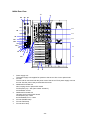
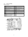
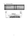
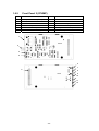
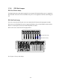
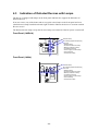
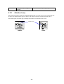
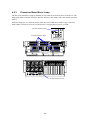
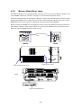
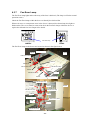
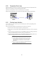
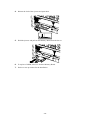
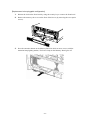
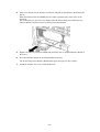
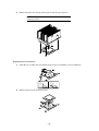
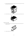
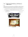
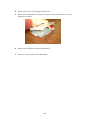
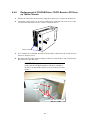
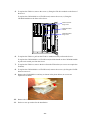
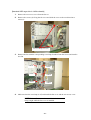
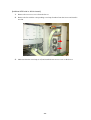
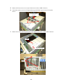
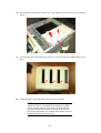
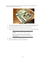
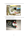
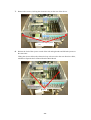
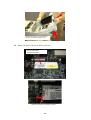
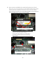
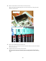
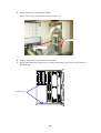
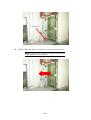
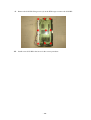
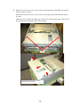
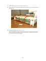
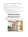
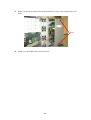
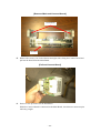
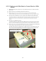
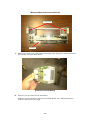
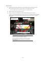
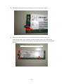
2.
Remove the heat sink. Swing it from side to side for easy removal.
NOTE: If the heat sink cannot be removed at all, heat it
with a dryer first.
[Replacement of processor]
1.
Open the lever of the socket on which the processor is installed to its end completely.
2.
Remove the processor from the socket.
- 76 -
3.
Install a new processor in the reverse procedure.
Note the direction of the processor in the installation. Match the pin mark on the
processor with that on the socket to install it correctly.
Pin mark
[Installation of heat sink]
Install the heat sink in the procedure reverse to the removal.
Notes:
Any used thermal interface cannot be reused.
If the heat sink is removed from the processor once, remove the thermal interface pasted on the
processor and heat sink completely by using a plastic paddle or plate. Then paste new thermal
interface on the heat sink
For replacement of processor board
Use the new thermal interface attached to the processor board of a maintenance device.
For replacement of processor
Use the new thermal interface attached to the processor of a maintenance device.
For replacement of heat sink
Use the new thermal interface attached to the heat sink of a maintenance device.
- 77 -
1.
Put the heat sink with the attached heat sink pasted on the processor quietly. The heat sink
has no specific front and rear sides.
2.
Fix the heat sink by using the screws (4) with the heat sink pressed downward by a hand.
[Replacement of VRM]
1.
Open the left and right levers on the VRM socket together to their ends and pull out the
VRM directly above.
2.
Install the VRM in the reverse procedure.
- 78 -
4.9.5
Replacement of CD-ROM Drive or CD/FD Board on
140Rd-4 Chassis
Note:
Do not apply this procedure to the replacement of the CD-ROM drive, CD/FD board or FD drive
installed in the Server on the 140He chassis because the FD cable must be removed. See the next
subsection for the replacement of these devices installed in the Server on the 140He chassis.
1.
Release the lock on the front bezel by using the security key to remove the front bezel.
2.
Remove the screw (1) fixing the CD-ROM module on the front face of the Server.
3.
Hold the handle on the CD-ROM module and pull out the module toward you to remove
it from the Server.
CD-ROM module fixing screw
CD-ROM module handle
CD/FD board
CD-ROM drive
CD-ROM tray
CD-ROM module
- 79 -
4.
Remove the screws (2) fixing the CD/FD board .
5.
Remove the CD-ROM drive and tray as shown in the photo below (no screws are
required to fix them).
6.
Remove the CD/FD board from CD-ROM drive.
7.
Do the reverse procedure for the installation.
- 80 -
4.9.6
Replacement of CD-ROM Drive, CD/FD Board or FD Drive
on 140He Chassis
1.
Release the lock on the front bezel by using the security key to remove the front bezel.
2.
Loosen the captive screw (2) on the rear of the Server, slide the rear access cover to the
rear direction, and lift the cover to remove it from the Server.
Captive screws
3.
If a 5-inch device is installed, disconnect all the cables connected to the 5-inch device to
remove it from the Server.
4.
Disconnect the FD cable from the mating connector on the FD drive. Do not disconnect
the connector at the other end.
IMPORTANT: Always disconnect the FD cable before
pulling out the CD-ROM module or FD drive installed in
the Server on the 140He chassis. If not, the FD cable will be
broken.
FD drive
FD cable
Disconnect FD cable from FD drive.
- 81 -
5.
To replace the FD drive, remove the screw (1) fixing the FD drive module on the front of
the Server.
To replace the CD-ROM drive or FD/CD board, remove the screw (1) fixing the
CD-ROM module on the front of the Server.
FD drive module
fixing screw
CD-ROM module
handle
CD-ROM module
fixing screw
6.
To replace the FD drive, pull out the FD drive module toward you from the Server.
To replace the CD-ROM drive or FD/CD board, hold the handle on the CD-ROM module
to pull out it toward you from the Server.
7.
To replace the FD drive, remove the drive from the FD bracket (no screws are required to
fix them).
8.
To replace the CD-ROM drive or FD/CD board, remove the screws (2) fixing the CD/FD
board to remove it.
9.
Remove the CD-ROM drive and tray as shown in the photo below (no screws are
required to fix them).
10.
Remove the CD/FD board from CD-ROM drive.
11.
Do the reverse procedure for the installation.
- 82 -
4.9.7
Replacement of Front Panel
The figure shows the Server mounted on the 140Rd-4 chassis. The Server on the 140He chassis is
different only in that it is mounted longitudinally. The replacement procedure is the same for both
the Server on the 140Rd-4 chassis and that on the 140He chassis if not specified especially.
1.
Release the lock on the front bezel by using the security key to remove the front bezel.
2.
Loosen the captive screw (1) fixing the front panel on the Server by using a proper
screwdriver.
3.
Hold the captive screw loosened in step 2 above and pull out the front panel module
toward you to remove it from the Server.
Front panel module fixing screw
Front panel module
4.
Do the reverse procedure for the installation.
- 83 -
4.10 Device Replacement (2)
Before any device other than those described in Section 4.9 above can be removed, the rear and
front access covers must be removed in the status that the Server is pulled out from the rack.
Refer to the User's Guide for how to pull out the Server from the rack.
4.10.1
1.
Removal or Installation of Rear Access Cover
Loosen the captive screw fixing the rear access cover by using a proper screwdriver, slide
the cover to the rear direction, and lift the cover to remove it from the Server.
Captive screw
Captive screws
2.
When the rear access cover is installed, check that no tools and screws are left in the
Server, that the proper devices are securely installed in the Server, and that there are no
uninstalled devices.
3.
Mate the tab on the rear access cover with the slot on the frame of the Server, slide the
rear access cover to the front direction while pressing it to the Server lightly, and fasten
the captive screw to fix it.
- 84 -
4.10.2
Removal or Installation of Front Access Cover
This description in this subsection applies only to the Server mounted on the 140Rd-4 chassis.
1.
[140Rd-4 chassis]
After removing the rear access cover, remove the screws (2) fixing the front access cover.
Then slide the front access cover to the rear direction and lift the cover to remove it from
the Server.
Front access cover fixing screw (×2)
2.
Mate the tab on the rear access cover with the slot on the frame of the Server, slide the
rear access cover to the front direction with it pressed to the Server, and fasten the screws
(2) to fix it.
- 85 -
4.10.3
Fan Replacement
The fans in the Server can be replaced even if the power is turned on (hot-swap replaceable).
The system can be operated if a single fan is defected (redundant feature). However, replace the
defected fan as soon as possible.
[140Rd-4 chassis]
1.
Remove the rear access cover from the Server.
2.
Remove the fan with the corresponding error lamp lit amber from the Server and install a
new fan.
3.
Make sure that the error lamp is off, and install the rear access cover on the Server.
FAN #4
FAN #5
FAN #1
FAN #6
FAN #2
FAN #3
- 86 -
[Standard HDD cage side in 140He chassis]
1.
Remove the rear access cover from the Server.
2.
Remove the screws (2) fixing the fan cover and slide the cover to the rear direction to
remove it.
Fan cover fixing screw (x2)
3.
Remove the fan with the corresponding error lamp lit amber from the Server and install a
new fan.
FAN #6
FAN #3
FAN #5
FAN #2
FAN #4
4.
FAN #1
Make sure that the error lamp is off, and install the fan cover and the rear access cover.
NOTE: Take sufficient care that no cables in the Server risk
being caught while the fan cover is installed.
- 87 -
[Additional HDD side in 140He chassis]
1.
Remove the rear access cover from the Server.
2.
Remove the fan with the corresponding error lamp lit amber from the Server and install a
new fan.
3.
Make sure that the error lamp is off, and install the rear access cover on the Server.
- 88 -
4.10.4
Replacement of Power Cage or Power BP
The figure shows the Server mounted on the 140Rd-4 chassis. The Server on the 140He chassis is
different only in that it is mounted longitudinally. The replacement procedure is the same for both
servers, except when specified otherwise.
1.
Make sure that the power of the Server is off, disconnect the AC cables from all the
power units and remove the power units from the Server.
2.
Remove the rear access cover from the Server.
3.
Loosen the captive screw (1) fixing the PCI access cover using a proper screwdriver to
remove the cover from the Server.
Thumb screw (×1)
4.
PCI access cover
Remove all the fans. (For the Server in the 140He chassis, first remove the fan cover and
the logic cover to remove all the fans.)
Logic cover
Fan cover
- 89 -
5.
Remove the front access cover (only for the Server on the 140Rd-4 chassis).
6.
Loosen the captive screws (2) fixing the fan cage and lift the cage to remove it from the
Server.
Lift the fan cage to
remove it.
Thumb screw (×2)
7.
Remove the screws (4) fixing the power cage and the open sensor switch cable connector.
Screw
Open sensor cable
Screw
- 90 -
8.
After pulling up the ejectors on the power cage, lift the power cage to remove it from the
Server.
Ejector
9.
10.
To replace the power BP, remove the screws (7) to remove the power BP from the power
cage.
Install the power cage in the Server in the reverse procedure.
NOTE: The power BP has a jumper switch used to specify
whether the Server is mounted on the 140Rd-4 or 140He
chassis. Set the jumper switch on the new power BP after
the replacement to be the same as that on the power BP
before the replacement. The position of the jumper switch is
shown in the figure on the next page.
- 91 -
* Jumper switch on power BP
Jumper switch location
Short: 140Rd-4 chassis (Rack)
Open: 140Hessis (Tower)
The jumper switch on a power BP of a maintenance device is short-circuited at the shipment from
the factory. If the power cage containing the power BP is installed in the Server on the 140He
chassis (tower), remove the jumper switch to make the power BP open.
- 92 -
4.10.5
Replacement of Management LAN Board or I/O Board
The figure shows the Server mounted on the 140Rd-4 chassis. The Server on the 140He chassis is
different only in that it is mounted longitudinally. The replacement procedure is the same for both
servers, except when specified otherwise.
Notes:
Before replacing the I/O Board, back up (save the server configuration information and the RMC
(Remote Management Controller: A-BMC) information by using the Offline Maintenance Utility.
Restore the information after the replacement.
Before the replacement, make sure that the +2.5 VDC output lamp on the I/O Board is off while
the AC cables are disconnected from the Server.
If the lamp is on, turn on the DC power of the Server once and run the POST before the
replacement. Then turn off the power of the Server again, disconnect the AC cables, and make sure
that +2.5 VDC output lamp on the I/O Board is off.
(With the lamp being on, the power is backed up by the onboard RAID battery.)
Before the +2.5 VDC output lamp can be checked, the rear access cover must be removed. The
lamp is installed below the power cage.
+2.5V output lamp
Location: 9K
- 93 -
The Server adapts the electronics bay structure. Accordingly, to remove the I/O Board, first
remove the electronics bay from the Server.
[Electronics bay]
1.
After making sure that the power of the server is off, remove the AC cables from all the
power units. Then remove the rear access, front access, and PCI access covers.
2.
If one or more PCI boards are installed, remove all the PCI boards.
Before removing a PCI board, remove the cables connected to the board (if applicable).
NOTE: Always insert the PCI cards into the original slots
on the new I/O Board without changing the installation
positions.
Before removing the PCI board, note the installation
position and put a label indicating the installation position
on the PCI board.
3.
Remove the fans, fan cage, and power cage.
4.
Pull out the A-BMC cable connected to the I/O Board.
- 94 -
5.
Remove the screw (1) fixing the management LAN board on the rear of the Server. Then
remove the management LAN board.
Management LAN board
fixing screw (×1)
6.
Disconnect the SCSI cables on the I/O Board.
The number of SCSI cables varies depending on the system configuration. Remove all the
SCSI cables connected to the I/O Board.
To remove a SCSI cable, always hold the cable tab.
Tab
SCSI cable
- 95 -
7.
Remove the screws (2) fixing the electronics bay on the rear of the Server.
Electronics bay fixing screw
(×2)
8.
Release the lock of the ejector at each of the left and right ends and lift both ejectors at
the same time.
Lifting the ejectors allows the electronics bay to be moved to the rear direction a little,
which then separates the I/O Board from the Main Board.
Ejector
- 96 -
Lift ejectors on both sides. The electronics
bay moves slightly backward.
9.
Hold the frame of the electronics bay and slide the bay in the rear direction to locate it at
the position shown in the figure below. Then hold the electronics bay with both hands to
lift it slowly as shown in the figure on the next page.
Move the electronics bay further.
cutout of the
frame
Protrusion of electronics bay
Move the electronics bay so that the protrusion can be seen from
the cutout of the frame.
- 97 -
Hold the electronics bay with both hands,
then lift it to remove from the chassis.
10.
Remove the battery cable from battery connector.
Onboard RAID battery
(BatteryModule+Board)
Remove the cable from the battery connector
- 98 -
11.
Remove the battery and DIMMs for the onboard RAID installed on the I/O Board.
Remove the screws (3) fixing the battery for onboard RAID and lift the battery module
(containing the battery and printed-circuit board) to remove it from the I/O Board.
Remove the locks at both ends of the socket holding the DIMM for onboard RAID and
pull up the DIMM module to remove it from the I/O Board.
Battery fixing screw for on-board RAID (×3)
IMPORTANT: The battery is in the power distribution
status if it is removed from the I/O Board.
Do not put the removed battery on a metallic plate to
prevent the components on the rear face from being
short-circuited.
Unlock the socket and remove on-board Raid DIMM.
- 99 -
12.
Remove all the initiators in the PCI slots on the electronics bay.
Remove the initiator lock appearing on the rear of the electronics bay. Then pull out the
initiators to remove them.
Insulator (plastic plate)
Insulators locks (indicated by circles)
13.
Remove the I/O Board from the electronics bay.
Remove the screws (15) fixing the electronics bay and I/O Board to remove the I/O Board
from the electronics bay.
14.
Install the electronics bay in the reverse procedure.
While the electronics bay is inserted into the Server or connected to the Main Board by
using the ejectors, check that no connector pins risk bending and that no cables risk being
caught.
- 100 -
4.10.6
Replacement of Additional HDD Cage or SCSI-BP (8
HDDs) on 140He Chassis
Notes:
To replace the additional HDD cage or SCSI-BP (8 HDDs), remove the HDDs installed in the
additional HDD cage from the Server.
Before the replacement, always back up the RAID configuration information.
After the replacement, insert the HDDs into the original slots without changing the installation
positions.
Before removing the HDDs, note their installation positions and put labels indicating the
installation positions on the HDDs.
Additional HDD cage
1.
After making sure that the power of the Server is off, disconnect the AC cables from all
the power units.
2.
Remove all the HDDs installed in the additional HDD cage from the Server.
3.
Remove the rear access cover from the Server.
4.
Remove the two fans in the additional HDD cage.
- 101 -
5.
Remove the fan box for additional HDDs.
Remove the screws (2) fixing the fan box to remove it.
Fixing screw (×2)
Additional HDD cage
fan box
6.
Remove all the cables connected to the SCSI-BP.
7.
Remove the HDD cage fixing screws (3 in all) on the front of the Server or the bottom of
the HDD cage.
Fixing screw (x2)
- 102 -
Fixing screw (×1)
8.
Slide the HDD cage in the rear direction to remove it from the Server.
NOTE: Slide the HDD cage slowly so that no cables can be
caught while the cage is removed.
- 103 -
9.
10.
Remove the SCSI-BP fixing screws (9) on the HDD cage to remove the SCSI-BP.
Install a new SCSI-BP in the Server in the reverse procedure.
- 104 -
4.10.7
Replacement of SCSI-BP (5HDD/3HDD) on 140Rd-4
Chassis
Notes:
To replace the SCSI-BP, first remove all the HDDs from the Server.
Before the replacement, always back up the RAID configuration information.
After the replacement of the SCSI-BP, insert the HDDs into the original slots without changing the
installation positions.
Before removing the HDDs, note their installation positions and put labels indicating the
installation positions on the HDDs.
Before the SCSI-BP can be replaced, the HDD cage must be removed.
HDD cage
1.
Make sure that the power of the Server is off, and disconnect the AC cables from all the
power units.
2.
Remove all HDDs, CD-ROM module and front panel module from the Server.
Remove any backup devices if installed.
3.
Remove the rear access and front access covers.
4.
For the Server of the 3.5-inch device model (3HDD model), pull out the SCSI and power
cables for 3.5-inch devices from the HDD cage.
5.
Remove the HDD cage fixing screws (2) on the front of the Server.
- 105 -
6.
Release the lock of the ejector at each of the left and right ends of the HDD cage and lift
both the ejectors at a time.
Release the lock of the ejector at each of the left and right ends and lift both the ejectors
at a time.
Lifting the ejectors allows the HDD cage to be moved to the front direction a little, which
then separate the SCSI-BP from the Connect Board.
Ejector
Lift the ejectors on both ends. The HDD
cage slightly moves forward.
- 106 -
7.
Lift the HDD cage upward to remove it from the Server.
8.
Remove the screws (12) fixing the HDD cage or SCSI-BP to remove the SCSI-BP from
the SCSI cage.
HDD cage
SCSI-BP
9.
Install the SCSI-BP in the reverse procedure.
While the SCSI-BP is connected to the Connect Board by using the ejectors, check the
secure installation of the HDD cage in the Server so that no connector pins risk being
bent or that no cables risk being caught.
- 107 -
4.10.8
Replacement of SCSI-BP(5HDD) on 140HE Chassis
Notes:
To replace the SCSI-BP, first remove all the HDDs from the Server.
Before the replacement, always back up the RAID configuration information.
After the replacement of the SCSI-BP, insert the HDDs into the original slots without changing the
installation positions.
Before removing the PCI board, note the installation position and put a label indicating the
installation position on the PCI board.
1.
Do steps 1 to 6 described in Subsection 4.10.7 above.
Remove all the HDDs instead of removing the HDDs only in the additional HDD cage.
2.
Remove the CD-ROM and front panel modules from the Server.
Remove any backup devices if installed.
IMPORTANT: Always disconnect the FD cable from the
FD drive before pulling out the CD-ROM module installed
in the Server on the 140He chassis. If not, the FD cable will
be broken.
3.
Remove the screws (2) fixing the fan cover to remove it.
And remove the screws (2) fixing the logic cover and slide the cover to the rear direction
to remove it.
4.
Remove the screws (2) fixing the front tower frame and slide the frame outward with it
lifted to remove the front tower frame from the Server.
Fixing screw (×2)
Device Cage
- 108 -
5.
Remove all the cables connected to the SCSI-BP and do steps 5 to 8 in Subsection 4.10.7
above.
Ejector
6.
Install a new SCSI-BP in the reverse procedure.
- 109 -
4.10.9
Replacement of Main Board or Connect Board on
140Rd-4 Chassis
1.
Make sure that the power of the Server is off, and disconnect the AC cables from all the
power units.
2.
Remove the Processor and Memory Boards from the Server.
3.
Remove the rear access cover, front access cover, PCI access cover, fans, fan cage, and
power cage.
4.
Do steps 4 and 5 in Subsection 4.10.5 to separate the I/O Board from the Main Board.
To replace the Main or Connect Board, the electronics bay does not need to be removed
from the Server but the I/O Board must be separated from the Main Board with the
ejectors.
5.
For the Server of the 3.5-inch device model (3HDD model), pull out the SCSI cables for
3.5-inch devices from the HDD cage.
To replace the Main or Connect Board, the power cables for 3.5-inch devices does not
need to be pulled out from the HDD cage but the SCSI cables must be pulled out.
6.
Do step 5 in Subsection 4.10.7 to separate the SCSI-BP from the Connect Board.
To replace the Main or Connect Board, the HDD cage does not need to be removed from
the Server but the SCSI-BP must be separated from the Connect Board with the ejectors.
7.
Remove the screws (2) fixing the Main Board to the Server. Then pull out the Main Board,
Connect Board, and brackets upward to remove them from the Server.
Remove the two screws, and then lift the
board to remove it from the chassis.
Fixing screw (×2)
- 110 -
[Removed Main and Connect Boards]
Connect Board
Main Board
8.
Remove the screws (2 at each of the left and right sides) fixing the Connect Board and
pull out the board from the Main Board.
[Pull-out Connect Board]
9.
Do the reverse procedure for the installation.
While the Connect Board is connected to the Main Board, check that no connector pins
risk being caught.
- 111 -
4.10.10 Replacement of Main Board or Connect Board on 140He
Chassis
1.
Make sure that the power of the Server is off, and disconnect the AC cables from all the
power units.
2.
Remove the Processor and Memory Boards from the Server.
3.
Remove the rear access cover, PCI access cover, fan cover, fans (two fans in the
additional HDD cage and six fans in the standard HDD cage), fan cage, and power cage.
4.
Do steps 4 and 5 in Subsection 4.10.5 to separate the I/O Board from the Main Board.
To replace the Main or Connect Board, the electronics bay does not need to be removed
from the Server but the I/O Board must be separated from the Main Board with the
ejectors.
5.
Do steps 1 to 5 in Subsection 4.10.8.
To replace the Main or Connect Board, the HDD cage does not need to be removed from
the Server but the SCSI-BP must be separated from the Connect Board with the ejectors.
6.
Remove the screws (2) fixing the Main Board to the Server. Then pull out the Main Board,
Connect Board, and brackets upward to remove them from the Server.
The figure shows the Server mounted on the 140Rd-4 chassis. On the 140He chassis, the
Server is only mounted longitudinally. The locations of the fixing screws are the same.
Remove the two screws, and then lift the
board to remove it from the chassis.
Fixing screw (×2)
- 112 -
[Removed Main and Connect Boards]
Connect Board
Main Board
7.
Remove the screws (2 at each of the left and right sides) fixing the Connect Board and
pull out board from the Main Board.
[Pull-out Connect Board]
8.
Do the reverse procedure for the installation.
While the Connect Board is connected to the Main Board, note sufficiently that any
connector pins may not be caught.
- 113 -
4.10.11 Replacement of Battery of DIMM for On-board RAID
Before replacing the battery or a DIMM, make sure that the +2.5 VDC output lamp on the I/O
Board is off if the AC cables are disconnected from the Server.
If the lamp is on, turn on the DC power of the Server once and run the POST before the
replacement. Then turn off the power of the Server again, disconnect the AC cables, and make sure
that +2.5 VDC output lamp on the I/O Board is off.
Before the +2.5 VDC output lamp can be checked, the rear access cover must be removed. The
lamp is installed below the power cage.
+2.5V output lamp
Location: 9K
Do not use any unauthorized batteries and DIMMs provided for other units.
The defined battery life is two years or 500 charge cycles. If a battery is charged for more than 500,
it is determined that its life has come. Then replace the battery.
- 114 -
[Procedure of checking battery charging count]
1.
Checking using the Windows event viewer
Start Windows to display the event log (application) of the event viewer on the screen.
Find the latest log of source "MegaServ.log" and event "5105" from the displayed log list.
Displaying the detailed event information allows the following screen to be displayed. To
check the charge cycles on the event viewer, PowerConsolePlus must be installed.
[Adapter X: No of Change Cycle =] in the Description item indicates the number of
charge cycles. (The above screen shows that the number of charge cycles is 86.)
2.
Checking using the MegaRAID Configuration Utility
After starting the MegaRAID Configuration Utility, select
[Objects]→[Adapter]→[Battery Information]. Then the battery status appears as follows.
[No of Cycles = ] indicates the number of charge cycles. (The above screen shows that
the number of charge cycles is 86.)
- 115 -
[Replacement]
1.
Make sure that the power of the Server is off, disconnect the AC cables from all the
power units and remove the rear access, front access and PCI access covers.
On the 140He chassis, also remove the fan cover from the Server.
2.
Remove the fans, fan cage and power cage.
3.
Remove the battery and DIMMs for onboard RAID installed on the I/O Board.
To remove the onboard RAID battery, remove the screws (3) fixing the battery and lift the
battery module (containing the battery and printed-circuit board) to remove it from the
I/O Board.
Battery for on-board RAID
(battery and board)
DIMM for on-board RAID
Fixing screw of battery for on-board Raid (×3)
IMPORTANT: The battery is in the power distribution
status if it is removed from the I/O Board.
Do not put the removed battery on a metallic plate to
prevent the components on the rear face from being
short-circuited.
- 116 -
4.
Pull out the cable from the removed battery (to prevent improper contacts).
5.
Remove the studs attached to the new battery that will be installed in the Server.
There are three studs, each of which is fixed to the battery with screws. Remove the
screws to remove the studs from the battery. (The removed studs and screws are not used
any more.)
Screw holes (Studs are located on the rear.)
- 117 -
6.
Connect the cable to the new battery that will be installed in the Server.
Note that the connector cannot be inserted incorrectly.
7.
Fill in the replacement date on labels (2) included in the package for maintenance devices.
Put one of the labels on the battery.
Put the other label near the nameplate of the Server (over the old onboard RAID battery
label.)
8.
Install the battery and DIMMs on the I/O Board.
Use the screws removed in step 3 for fixing the battery.
(The package for maintenance devices includes spare screws.)
9.
10.
Install the power cage, fan cage, fans and all the covers to recover the original state.
Connect the power cables to the power units, turn on the power of the Server, and start
the MegaRAID Configuration Utility.
Select [Objects]→[Adapter]→[Reset Battery Charge Counter] from the Top menu and
select [Yes] to clear the charging cycles.
NOTE: The new battery is not charged. The battery is fully
charged by continuous operation about six hours after the
Server is started.
4.10.12 Replacement of PCI Board
Refer to the User's Manual for the replacement procedure and notes on the PCI Board.
- 118 -
4.11 Jumper Settings
The jumper pins in the Server are located on the I/O Board and Power-BP.
The jumpers and their setting values are described below.
[I/O Board: G7HRH]
2
1
4
6
8
10
12
3
5
7
9
11
Location: JP2
2
4
6
8
2
4
6
8
10 12
1
3
5
7
1
3
5
7
9
Location: JP3
- 119 -
Location: JP4
11
<Settings of jumpers on I/O Board (G7HRH)>
[Location: JP2]
Pin
1-2
3-4
5-6
7-8
9-10
11-12
Function name
BMC Boot BlockWrite Enable
FRB3 Timer Disable
BMC Force Update
BMC DNS Setting Clear Enable
Test LED Enable
(Not used)
Default
Open
Open
Open
Open
Open
Short
Remarks
Default
Open
Open
Open
Open
Remarks
Short prohibited
Short prohibited
Default
Open
Open
Open
Open
Open
Short
Remarks
[Location: JP3]
Pin
1-2
3-4
5-6
7-8
Function name
BIOS Select
BIOS Image Forced Mode
BIOS Boot Block Write Enable
TEST Mode2
[Location: JP4]
Pin
1-2
3-4
5-6
7-8
9-10
11-12
Function name
CMOS Clear
Password Clear
Inspection Mode
TEST Mode11
BIOS Recovery
(Not used)
Test Mode1/2
Mode2
H
H
L
L
Mode1
H
L
H
L
Function
Normal
Debug Menu
Detailed SEL
Other
- 120 -
Short
<Settings of jumpers on Power-BP (G7HMM)>
Jumper switch location
(Location: P8)
Short: 140Rd-4 chassis (Rack)
Open: 140He chassis (Tower)
- 121 -
5. System BIOS
5.1
BIOS SETUP
When the power of the Server is turned on, POST is executed to display a full screen logo (default
BIOS SETUP settings). If an error is detected during the execution of POST, the test execution
screen appears instead to indicate the error.
The screen switching can be modified by the ESC key or the setting of BIOS SETUP.
To change the setting, press the <F2> key during the execution of POST to boot BIOS SETUP and
select the menu item to be changed in the menu by using arrow keys appropriately. Refer to the
User's Guide of the Server for details of BIOS SETUP.
For POST error messages and the consequent actions to take, see Chapter 8.
5.2
Duplication of System BIOS
The system BIOS of the Server is duplicated to allow two BIOSs to be operated, which are called
primary BIOS and secondary BIOS.
In the normal operation, the primary BIOS is booted to operate the system. At the occurrence of a
data error in the primary BIOS or a fault of the device in which the system BIOS is stored, the
secondary BIOS is booted as soon as possible to operate the system. This operation can avoid
system shutdown caused by a malfunction of the system BIOS.
Both the primary and secondary BIOSs installed in the Server at the shipment are the system BIOS
of the latest version. Each system BIOS update makes the secondary BIOS updated to be the
primary BIOS.
Then the switched primary BIOS is booted to operate the system.
For the actions taken at the occurrence of a data error in the primary BIOS or a fault of the device
in which the system BIOS is stored, see Chapter 8.
- 122 -
6. RAS Function
6.1
Logging
When an event (including fan fault, excess temperature, abnormal voltage, memory error, and
internal detection error) occurs, the system provides firmware logging and lights amber the
corresponding LEDs. Further, ESMPro views the log to make proper troubleshooting.
6.2
Memory Degrading Operation
The system is designed to be operable under memory degrading.
If a memory error is detected during POST, the system is started with the defected memory block
cut out.
The memory degrading operation can be known by proper message display by POST, lighting
umber of the relevant error LED, and indication by BIOS SETUP.
6.3
Temperature Monitoring
Abnormally high temperature, warning high temperature, warning low temperature, and
abnormally low temperature can be set as temperature errors. If a temperature error occurs,
logging, warning, or system shutdown occurs before OS boot. After the OS is booted, the action
taken against a temperature error depends on the ESMPRO setting.
6.4
Watchdog Timer (WDT)
The watchdog timer is normally installed in the system. Depending on the setting of the watchdog
timer, the clearing process may not be done within the defined period. Then the system is run out
to cause a panic to occur.
- 123 -
7. Remote Management Function
The Baseboard Management Controller (BMC), the system management LSI normally installed in
the Server, can be used to monitor the status of internal hardware including power supplies, fans,
and temperature.
In addition, the Server can be managed remotely through a management network to provide
hardware status monitoring and KVM (keyboard, video, and mouse) control.
Refer to the User's Guide for the detailed description, notes, and setup procedure of the remote
management function.
If an error occurs during the use of the remote management function, the relevant error dialog
appears on the management PC. For the error messages and the actions taken against the messages,
see Chapter 8.
- 124 -
8. Troubleshooting
When a fault occurs, it is indicated in several ways.
Take the proper action against a fault depending on each of the indications.
"Troubleshooting" in the User's Guide of the Server includes check lists on faults. See the
checklists to help you.
Take the action described in the item related to the fault that occurred, if any.
8.1
Error LED Indications
When an hardware error occurs, some of the LEDs on the front panel and/or devices light or blink
amber. Replace the device in which the error occurs following the description in section 4.3.
8.2
Locations of Devices Apperaing in Error Messages
The locations of installed devices appearing in error messages are as follows:
- 125 -
8.2.1
Fan
FAN5 Fault lamp
FAN4 Fault lamp
Fan 5
FAN6 Fault lamp
Fan 4
Fan 6
Fan 1
Fan 3
FAN1 Fault lamp
FAN3 Fault lamp
FAN2 Fault lamp
Fan 2
Fan 3
Fan 6
Fan 2
Fan 8
Fan 5
Fan 1
Fan 4
Fan 7
- 126 -
8.2.2
Memory Board and DIMM
Memory board slot #1
Memory board slot #2
Memory board slot #4
Memory board slot #3
Memory board slot #1
Memory board slot #2
Memory board slot #4
Memory board slot #3
DIMM slot #4
DIMM slot #3
DIMM slot #2
DIMM slot #1
Memory board slot
#1
1 DIMM #1 DIMM
2 DIMM #2 Group #1
3 DIMM #3 DIMM
4 DIMM #4 Group #2
Memory board slot
#2
DIMM #1 DIMM
DIMM #2 Group #3
Memory board slot
#3
DIMM #1 DIMM
DIMM #2 Group #5
Memory board slot
#4
DIMM #1 DIMM
DIMM #2 Group #7
DIMM #3 DIMM DIMM #3 DIMM DIMM #3 DIMM
DIMM #4 Group #4 DIMM #4 Group #6 DIMM #4 Group #8
- 127 -
8.2.3
Processor and VRM
Processor #1
Processor #2
Processor #4
- 128 -
Processor #3
8.3
POST Error Messages
When the power of the server is turned on, POST (Power On Self-Test) automatically runs to
check the I/O board, memory board, processor, keyboard, and mouse. When POST detects an error,
it displays an error message on the display unit screen. (Some error messages are displayed along
with the action to be taken.)
If the error message listed in the table is displayed on the screen, take a measure according to
"Action" column. When several actions are to be taken, determine the action appropriately.
On-screen message
Action
0200
•
Failure Fixed Disk
Replace the hard disk drive.
Replace the cable.
• Replace the HDD cage.
• Replace the I/O board.
• Connect the keyboard connector again,
and restart the system.
• Replace the keyboard.
• Replace the I/O board.
• Connect the keyboard connector again,
and restart the system.
• Replace the keyboard.
• Replace the I/O board.
• Check if the key switch has been locked
(being pushed).
• Replace the keyboard.
• Replace the I/O board.
• Start Setup to reconfigure the monitor.
• Replace the I/O.
• Check if ECC 1-bit/multi-bit error is
recorded in the system event log. If the
error is recorded, replace the relevant
DIMMs in pair.
After replacement, start SETUP and
execute [Clear DIMM Error].
• Replace the memory board.
• Replace the I/O board.
Replace the lithium battery.
After replacement, start SETUP to set the
current time and date.
This error may occur if the system is
forcedly shutdown during POST.
Start BIOS SETUP to reconfigure the
system.
Start BIOS SETUP to set the password
again.
Replace the I/O board.
Start BIOS SETUP to set the date and time
again.
Replace the I/O board.
•
0210
0211
Stuck Key
Keyboard error
0212
Keyboard Controller Failed
0213
Keyboard locked – Unlock key switch
0220
Monitor type does not match CMOS –
Run SETUP
0230
0231
0232
System RAM Failed at offset
Shadow Ram Failed at offset
Extended RAM Failed at address line
0250
System battery is dead – Replace and
run SETUP
0251
System CMOS checksum bad - Default
configuration used
0252
Password checksum bad - Passwords
cleared
System timer error
Real time clock error
Check date and time Settings
0260
0270
0271
- 129 -
On-screen message
Action
0280
Previous boot incomplete - Default
configuration used
02B0
Diskette drive A error
02B1
Diskette drive B error
02B2
Incorrect drive A type – run SETUP
02B3
Incorrect drive B type – run SETUP
02D0
System cache error –Cache disabled
02D1
System Memory exceeds the CPU's
caching limit
02F5
02F6
02F7
0500
DMA test failed
Software NMI Failed
Fail-safe Timer NMI Failed
Expansion ROM not initialized PCI Slot
01
Expansion ROM not initialized PCI Slot
02
Expansion ROM not initialized PCI Slot
03
Expansion ROM not initialized PCI Slot
04
Expansion ROM not initialized PCI Slot
05
Expansion ROM not initialized PCI Slot
06
Expansion ROM not initialized PCI Slot
07
Expansion ROM not initialized PCI Slot
08
IDE configuration
Changed
COM A configuration changed
COM A config. Error - device disabled
COM B configuration changed
COM B config. Error - device disabled
Floppy configuration changed
Floppy config. Error - device disabled
Parallel port Configuration changed
Parallel port config.
Error - device disabled
The system will start with "Uncached" state.
Start BIOS SETUP to reconfigure the
system.
Check the FDD cable connection.
Replace the FDD.
Replace the FDD cable.
Replace the CD/FD board.
Check the settings of BIOS SETUP.
Replace the I/O board.
Start SETUP to check if [Floppy Options] [Diskette A:] is set to [1.44/1.25Mb 3 1/2"].
Replace the FDD.
Check the settings of BIOS SETUP.
Replace the I/O board.
Replace the processor.
Replace the processor board.
Replace the processor.
Replace the processor board.
Replace the I/O board.
0501
0502
0503
0504
0505
0506
0507
0611
0613
0614
0615
0616
0617
0618
0619
061A
Set [Option ROM] for the PCI slot to which
the boot device is connected to "Enabled",
and "Disabled" for other slots.
Replace the PCI board.
Replace the I/O board.
Replace the connected devices.
- 130 -
On-screen message
Action
0B00
Replace the I/O board.
0B1B
0B1C
0B22
0B28
0B29
0B2A
0B2B
0B30
0B31
0B32
0B33
0B34
0B35
0B36
0B37
0B50
0B51
0B52
0B53
0B5F
0B60
0B61
0B62
0B63
0B64
0B65
0B66
0B67
Rebooted during BIOS boot at post
Code
PCI System Error on
Bus/Device/Function
PCI Parity Error on
BUS/Device/Function
Processors are installed out of order.
Unsupported CPU detect on CPU
Slot1
Unsupported CPU detect on CPU
Slot2
Unsupported CPU detect on CPU
Slot3
Unsupported CPU detect on CPU
Slot4
Fan 1 Alarm occurred.
Fan 2 Alarm occurred.
Fan 3 Alarm occurred.
Fan 4 Alarm occurred.
Fan 5 Alarm occurred.
Fan 6 Alarm occurred.
Fan 7 Alarm occurred.
Fan 8 Alarm occurred.
Processor#1 with error taken off line.
Processor#2 with error taken off line.
Processor#3 with error taken off line.
Processor#4 with error taken off line.
Forced to use CPU with error.
DIMM group #1 has been disabled
DIMM group #2 has been disabled
DIMM group #3 has been disabled
DIMM group #4has been disabled
DIMM group #5 has been disabled
DIMM group #6 has been disabled
DIMM group #7 has been disabled
DIMM group #8 has been
disabled
0B70
The error occurred during temperature
sensor reading
0B71
System Temperature out of the range
Replace the I/O board.
Replace the PCI board.
Replace the processor.
Clean the fan.
Replace the fan.
Replace the processor.
Replace the processor board.
After replacement, start SETUP and
execute [Clear CPU Error].
Update the system with the latest BIOS.
Insert the DIMM again.
Check if ECC 1-bit/multi-bit error is
recorded in the system event log. If the
error is recorded, replace the relevant
DIMMs in pair.
If the failed DIMMs cannot be identified,
replace all the DIMMs in the relevant group.
Replace the memory board.
After the replacement, start SETUP and
execute [Clear DIMM Error].
Replace the front panel.
Replace the CPU.
Replace the Processor board.
Replace the I/O board.
Set the room temperature in the range
between 10 to 35ºC.
Check the system event log to identify the
thermal sensor which has detected the
out-of-range temperature.
- 131 -
On-screen message
Action
0B74
Replace the I/O board.
0B75
The error occurred during voltage
sensor reading
System Voltage out of the range
0B78
0B7C
The error occurred during fan sensor
The error occurred during the
redundant power module confirmation
0B7D
The normal operation can't be
guaranteed with use of only one PSU
0B80
0B81
BMC Memory Test Failed.
BMC Firmware Code Area CRC check
failed.
BMC Core hardware failed.
BMC IBF or OBF check failed.
BMC SEL area full
0B82
0B83
0B8A
0B8B
0B8C
0B8D
0B8E
0B8F
0B90
0B91
0B92
0B93
0B94
0B95
0B96
0B97
0B98
0B99
0B9A
0B9B
0B9C
0B9D
0B9E
0B9F
0BB0
0BB1
BMC progress check timeout
BMC command access faild
Could not redirect the console - BMC
Busy
Could not redirect the console - BMC
Error
Could not redirect the console - BMC
Parameter Error
BMC PlatformInformation Area
Corrupted.
BMC Update firmware corrupted
Internal Use Area of BMC FRU
corrupted
BMC SDR Repository Empty.
IPMB signal lines do not respond.
BMC FRU device failure.
BMC SDR Repository Failure
BMC SEL device failure.
BMC RAM test error
BMC Fatal hardware error
BMC not responding
Private I2C bus not responding
BMC internal exception
BMC A/D timeout
SDR repository
SEL corrupt
SMBIOS – SROM data read error
Check the system event log to identify the
voltage sensor which has detected the
out-of-range voltage.
Replace the I/O board.
Replace the power supply unit.
Check the AC cord connection.
Replace the power supply unit.
Power off the system. Disconnect the power
cable and connect it again, cycle the power,
then restart the system.
Replace the I/O board.
Check the system event log, and then clear
it.
Power off the system. Disconnect the power
cable and connect it again, cycle the power,
then restart the system.
Replace the I/O board.
Power off the system. Disconnect the power
cable and connect it again, cycle the power,
then restart the system.
Replace the I/O board.
Power off the system. Disconnect the power
cable and connect it again, cycle the power,
then restart the system.
Replace the I/O board.
Replace the relevant board.
- 132 -
On-screen message
Action
0BC0
Check the CPU installation.
Replace the CPU.
Replace the processor board.
Replace the I/O board.
0BC1
0BC2
0BC3
0BD0
0BD1
0BD2
0BD3
0BD4
0BD5
0BD6
0BD7
0BD8
0BD9
0BDA
0BDB
0BDC
0BDD
0BDE
0BE8
0BE9
0BEA
8120
8121
8122
8123
8124
8125
8126
8127
8130
8131
POST detected startup failure of
CPU#1
POST detected startup failure of
CPU#2
POST detected startup failure of
CPU#3
POST detected startup failure of
CPU#4
1st SMBus address not acknowledged.
1st SMBus device Error detected.
1st SMBus timeout.
2nd SMBus address not
acknowledged.
2nd SMBus device Error detected.
2nd SMBus timeout.
3rd SMBus address not acknowledged.
3rd SMBus device Error detected.
3rd SMBus timeout.
4th SMBus address not acknowledged.
4th SMBus device Error detected.
4th SMBus timeout.
5th SMBus address not acknowledged.
5th SMBus device Error detected.
5th SMBus timeout.
IPMB address not acknowledged
IPMB device error detected
IPMB timeout
Unsupported DIMM detected in DIMM
group #1
Unsupported DIMM detected in DIMM
group #2
Unsupported DIMM detected in DIMM
group #3
Unsupported DIMM detected in DIMM
group #4
Unsupported DIMM detected in DIMM
group #5
Unsupported DIMM detected in DIMM
group #6
Unsupported DIMM detected in DIMM
group #7
Unsupported DIMM detected in DIMM
group #8
Mismatch DIMM detected in DIMM
group #1
Mismatch DIMM detected in DIMM
group #2
After replacement, start SETUP and
execute [Processor Retest].
Replace the I/O board.
Replace the PCI Option card.
Replace the processor board.
Replace the I/O board.
Replace the memory board.
Replace the DIMM.
Check the power supply unit connection or
replace the power supply unit.
Replace the Power-BP.
Replace the I/O board.
Replace the processor.
Replace the processor board.
Replace the I/O board.
Replace the front panel.
Replace the SCSI-BP.
Replace the I/O board.
Replace the front panel.
Replace the SCSI-BP.
Replace the I/O board.
Replace the DIMMs in relevant group.
Use the same type of DIMMs in the relevant
group.
- 133 -
On-screen message
8132
Action
8200
Mismatch DIMM detected in DIMM
group #3
Mismatch DIMM detected in DIMM
group #4
Mismatch DIMM detected in DIMM
group #5
Mismatch DIMM detected in DIMM
group #6
Mismatch DIMM detected in DIMM
group #7
Mismatch DIMM detected in DIMM
group #8
DIMM group #1 with error is enabled
DIMM group #2 with error is enabled
DIMM group #3 with error is enabled
DIMM group #4 with error is enabled
DIMM group #5 with error is enabled
DIMM group #6 with error is enabled
DIMM group #7 with error is enabled
DIMM group #8 with error is enabled
NVRAM cleared by Jumper
Password Cleared by Jumper
Mismatch processor Speed detected
on Processor 1
Mismatch processor Speed detected
on Processor 2
Mismatch processor Speed detected
on Processor 3
Mismatch processor Speed detected
on Processor 4
Processor 1 not operating at intended
frequency
Processor 2 not operating at intended
frequency
Processor 3 not operating at intended
frequency
Processor 4 not operating at intended
frequency
All Processor not operating at intended
frequency
Online Spare Memory was not ready
8201
Mirroring Memory was not ready.
8202
Memory RAID was not ready
8133
8134
8135
8136
8137
8140
8141
8142
8143
8144
8145
8146
8147
8150
8151
8160
8161
8162
8163
8170
8171
8172
8173
817F
Replace the DIMMs in relevant group.
Set the jumper switch as before after
turning off the power.
Check the frequency of CPU. Replace the
CPU of rated frequency.
Check the frequency of CPU. Replace the
CPU of rated frequency.
Check the frequency of CPU. Replace the
CPU of rated frequency.
Use DIMMs of the same type.
The dedicated maintenance parts are
specified for online spare memory.
Use DIMMs of the same type.
The dedicated maintenance parts are
specified for online spare memory.
Check the memory capacity and type for all
the DIMMs. Check also if they are correctly
installed.
- 134 -
On-screen message
Action
8300
Update the system with the latest BIOS.
Replace the I/O board.
Secondary BIOS is corrupted
- 135 -
8.4
Beep Codes
If an error occurs during the POST, the server beeps, indicating the type of error.
Each number indicates the number of short beeps, and a hyphen indicates a pause. For example,
the beep interval 1-3-1-3 indicates 1 beep, pause, 3 beeps, pause, 1 beeps, pause, and 3 beeps
notifying that the keyboard controller error.
Beep
code
1-2
1-2
1-2-2-3
1-3-1-1
1-3-1-3
1-3-3-1
1-3-4-1
1-3-4-3
1-4-1-1
1-5-1-1
1-5-2-2
1-5-2-3
1-5-4-4
2-2-3-1
Description
Action (module to be replaced)
Video configuration If nothing is displayed, check if the connector of the display
fails
unit is properly connected. If the error persists, replace the I/O
board.
If an expansion of Option ROM for additionally installed PCI
OPTION ROM
board is not displayed, check if the PCI board is properly
Checksum error
installed. If the error persists, replace the I/O board or PCI
board.
ROM checksum
Clear CMOS.
error
Replace the I/O board.
DRAM refresh test Check if the DIMM and memory boards are properly
error
connected. If the error persists, replace DIMM, memory board
or I/O board.
Keyboard
Disconnect the keyboard and connect it again. If the error
controller test error persists, replace the I/O board.
Memory is not
Check if the DIMM and memory boards are properly
detected. Or,
connected. If the error persists, replace DIMM, memory board,
DIMM type is
or I/O board.
incorrect.
DRAM Address
Check if the DIMM and memory boards are properly
error
connected. If the error persists, replace DIMM, memory board,
or I/O board.
DRAM test Low
Check if the DIMM and memory boards are properly
Byte error
connected. If the error persists, replace DIMM, memory board,
or I/O board.
DRAM test High
Check if the DIMM and memory boards are properly
Byte error
connected. If the error persists, replace DIMM, memory board,
or I/O board.
Processor fails to
Check if the processor and processor board are properly
start.
installed. If the error persists, replace the processor, processor
board, or I/O board.
No processor error Check if the processor and processor board are properly
installed. If the error persists, replace the processor, processor
board, or I/O board.
Processors of
Check if the additionally installed processor is supported by
various types and the server.
voltages coexist.
Check if the processor and processor board are properly
installed. If the error persists, replace the processor, processor
board, or I/O board.
Power failure
Check if internal boards are connected properly.
I/O board, front panel board, or processor board may be faulty.
Identify the failing board.
Unexpected
Replace the I/O board.
interrupt test error
NOTE: Beep code 1-5-4-2 informs you that AC power
supply is interrupted due to power failure or momentary
- 136 -
voltage drop and the system is restarted. This is not an error.
- 137 -
8.5 Operation of Battery and DIMM for Onboard RAID
8.5.1
Error Indication by POST
The information on onboard RAID is normally indicated by POST as follows:
LSI MegaRAID BIOS
Version XXX (Build XXX XX XXXX)
Copyright(C) 2005 LSI Logic Corp.
HA-X (Bus XX Dev XX) MegaRAIS SCSI 320-2E
Standard FW XXXX DRAM = 256MB (SDRAM)
Battery module is present on adapter
Channel-0 ID-14 -- XXX XXXXX
Channel-1 ID-14 -- XXX XXXXX
X Logical Drive(s) found on the host adapter.
X Logical Drive(s) handled by BIOS
Press <Ctrl><M> or <Enter> to Run Config Utility
Or Press <Ctrl><H> for WebBIOS
The actions taken against error messages other than above are as follows:
Error messages about the battery
The battery for onboard RAID may be defected. Replace the battery for onboard RAID
following the description in Subsection 4.10.11.
If the similar message appears after the replacement, replace the I/O Board.
Error messages about the memory
A DIMM for onboard RAID may be defected. Replace the defected DIMM for onboard
RAID following the description in Subsection 4.10.11.
If the similar message appears after the replacement, replace the I/O Board.
Error messages about the RAID key
The RAID key, a device on the I/O Board, may be defected. Replace the I/O Board.
Error messages about the HDD
An HDD may be defected. Check the LEDs on the HDDs to replace the defected HDD.
8.5.2
Error Messages by Windows Event Log
When Power Console Plus is installed in the Server, the onboard RAID log can be checked by the
event log (application) of the Event Viewer. Isolate the suspicious device depending on the error
type to replace the device.
- 138 -
8.5.3
Battery Status Check by MegaRAID Configuration Utility
Starat the MegaRAID Configuration Utility and select [Objects]→[Adapter]→[Battery
Information]. Then the battery status appears as follows.
Item
Meaning
Indication
Action
Back Up
Module
Presence of
battery module
PRESENT
ABSENT
Battery Pack
Presence of
battery pack
PRESENT
ABSENT
Temperature
Temperature
status
GOOD
HIGH
Voltage
Voltage status
GOOD
BAD
Fast
Charging
Fast charge
status
COMPLETED
IN_PROGRESS
No of Cycles
Number of fast
charge cycles
(Numerical
characters)
None
Check the installation of the battery
module.
Replace the battery module.
None
Check the installation of the cable coming
out of the battery pack.
Replace the battery module.
None
Check fans.
Replace battery module.
None
Check the installation of the battery
module.
Replace battery module.
None
None. However, replace the battery module
if this status continues for longer then eight
hours.
Replace the battery if the value exceeds
500.
NOTE: The defined battery life is two years or 500 charge
cycles. If a battery is charged for more than 500, it is
determined that its life has come to an end. Replace the
battery.
The new battery is not charged. The battery is charged fully
by continuous operation about six hours after the Server has
started.
- 139 -
8.6 Error Messages in Remote Management
While the remote management is used, error messages may appear on the management PC at the
occurrence of an error. This section lists the error messages and the actions taken against the
errors.
[Fatal error]
No.
Error message
Action
1
Fatal error. JavaVM is
terminated.
2
A fatal software error
occurred.
Login to the system again. If the same message
appears again, set up the system again. If the same
message reappears, replace the I/O Board.
Login to the system again. If the same message
appears again, set up the system again. If the same
message reappears, replace the I/O Board.
[Error at login]
No.
Error message
Action
1
Authentication error
Check the user name and password. Then reenter
them again.
[Access authority error]
No.
Error message
Action
1
The operation is not
permitted. The authority level
is not enough.
Perform the operation in the administrator level.
Contact your administrator.
[Network errors]
No.
Error message
Action
1
HTTP communication failed.
2
The IP address could not be
solved.
The operation cannot reach
the target host.
A network error occurred.
After checking the network environment, retry the
operation. If the operation fails several times, replace
the Management LAN Card. If the error still occurs,
replace the I/O Board.
Check the network environment. The Remote KVM
Console is not available in the connection through a
proxy.
3
4
5
The applet is downloaded
unsuccessfully.
After checking the network environment, retry the
operation. If the operation fails several times, replace
the Management LAN Card. If the error still occurs,
replace the I/O Board.
After checking the network environment, retry the
operation. If the operation fails several times, replace
the Management LAN Card. If the error still occurs,
replace the I/O Board. If the SSL is made effective,
only a single client can connect to the unit at a time.
Retry the operation after terminating the operation of
another client.
- 140 -
No.
Error message
Action
6
The RMCP+ session is
closed.
The RMCP+ session is
established unsuccessfully.
RMCP+ is sent
unsuccessfully.
The specified RMCP+
protocol is unavailable.
The BMC resource is not
enough to establish a new
RMCP+ session.
Timeout occurred in the
RMCP+ connection.
After checking the network environment, retry the
operation. If the operation fails several times, replace
the Management LAN Card. If the error still occurs,
replace the I/O Board.
7
8
9
10
11
Retry the operation after the connection from another
client is terminated.
After checking the network environment and the
Server, retry the operation. If the operation fails
several times, replace the Management LAN Card. If
the error still occurs, replace the I/O Board.
[BMC errors]
No.
Error message
Action
1
The IPMI request is aborted.
2
An illegal response is
received from the BMC.
The BMC does not support
the features of IPMI 2.0.
The IPMI command is
executed unsuccessfully.
The IPMI message is sent
unsuccessfully.
This may be caused by network congestion. Retry
the operation. If the operation fails several times,
replace the Management LAN Board. If the error still
occurs, the BMC may be defected. Replace the I/O
Board.
Check the Server. If no specific problems are found,
the BMC may be defected. Replace the I/O Board.
3
4
5
6
7
An illegal IPMI command is
requested.
The specified target is not
found.
After checking the network environment, retry the
operation. If the operation fails several times, replace
the Management LAN Card. If the error still occurs,
replace the I/O Board.
Check the Server. If no specific problems are found,
the BMC may be defected. Replace the I/O Board.
- 141 -
[Errors no remote KVM console]
No.
Error message
Action
1
The remote KVM console is
invalidated unsuccessfully.
The remote KVM console is
validated unsuccessfully.
KVM packets are sent
unsuccessfully.
The KVM request is aborted.
After checking the network environment, retry the
operation. If the operation fails several times, replace
the Management LAN Card. If the error still occurs,
replace the I/O Board.
2
3
4
5
UDP packets are sent
unsuccessfully.
6
The remote KVM console is
unavailable because it is
made invalid.
The remote KVM console is
already used by another
client.
The remote KVM console is
terminated unsuccessfully.
The BMC configuration is set
unsuccessfully.
The UDP connection is
closed.
7
8
9
10
This does not indicate a specific error. Click [OK] to
close the message dialog box.
After checking the network environment, retry the
operation. If the operation fails several times, replace
the Management LAN Card. If the error still occurs,
replace the I/O Board.
Make the Remote KVM Console effective (permitted)
following the User's guide.
After the client now using the Remote KVM Console
terminates, retry the operation.
Use the Remote KVM Console after three minutes or
longer have passed.
After checking the network environment, retry the
operation. If the operation fails several times, replace
the Management LAN Card. If the error still occurs,
replace the I/O Board.
[Errors on system event log (SEL) display]
No.
Error message
Action
1
The BMC SEL is cleared
unsuccessfully.
The SEL is acquired
unsuccessfully.
This may be caused by network congestion. Retry
the operation. If the operation fails several times,
replace the Management LAN Board. If the error still
occurs, the BMC may be defected. Replace the I/O
Board.
2
[Errors on sensor device report (SDR) display]
No.
Error message
Action
1
The SDR is acquired
unsuccessfully.
This may be caused by network congestion. Retry
the operation. If the operation fails several times,
replace the Management LAN Board. If the error still
occurs, the BMC may be defected. Replace the I/O
Board.
- 142 -
[Errors on maintenance/replacement device information (FRU) display]
No.
Error message
Action
1
The DRU is acquired
unsuccessfully.
This may be caused by network congestion. Retry
the operation. If the operation fails several times,
replace the Management LAN Board. If the error still
occurs, the BMC may be defected. Replace the I/O
Board.
[BMC configuration errors]
No.
Error message
Action
1
2
The setting failed.
The BMC configuration is
acquired unsuccessfully.
3
After checking the network environment, retry the
operation. If the operation fails several times, replace
the Management LAN Card. If the error still occurs,
replace the I/O Board.
Retry the operation after a while.
The BMC is now used by
another software. Retry the
operation after a while.
The BMC configuration file is The BMC configuration file may be broken. Check
the file.
illegal.
Required XML tags are not
found.
The file is saved
The BMC configuration file is saved incorrectly. After
unsuccessfully.
changing the storage destination, retry the operation.
The user name is too long.
The user name should be up to 32 characters.
The user name includes one
The user name can only accept alphanumeric
or more illegal characters.
characters, "-" (minus sign) and "_" (underscore).
The password is too long.
The password should be up to 16 characters.
The password does not
Reenter the password.
match the registered one.
Numeric characters are only available.
The HTTP port number is
illegal.
The SSL port number is
illegal.
The HTTP port number is the The port numbers cannot be the same with each
same as the SSl port number. other. Specify different port numbers.
The login trial period is illegal. Numeric characters are only available.
The possible login failure
count is illegal.
The account lock period is
illegal.
The IP address is illegal.
Specify the IP address with numeric characters and
periods.
The subnet mask is illegal.
The default gateway is illegal.
The IP address of the DNS
server is illegal.
The host name is illegal.
The host name can only accept alphanumeric
characters, "-" (minus sign) and "_" (underscore). It
should be up to 256 characters.
4
5
6
7
8
9
10
11
12
13
14
15
16
17
18
19
20
21
- 143 -
No.
Error message
Action
22
The domain name is illegal.
23
The SMTP server address is
too long.
The SMTP port number is
illegal.
The number of retries is
illegal.
The retry period is illegal.
The value of "To" is too long.
The value of "From" is too
long.
The value of "Subject" is too
long.
The message is too long.
The file is opened
unsuccessfully.
The file is closed
unsuccessfully.
The directory cannot be
opened.
Timeout occurred.
The domain name can only accept alphanumeric
characters, "-" (minus sign) and "_" (underscore). It
should be up to 256 characters.
The SMTP server address should be up to 256
characters.
Numeric characters are only available.
24
25
26
27
28
29
30
31
32
33
34
The value should be up to 256 characters.
The value should be up to 512 characters.
A message should be up to 4062 characters.
The specified file may not exist. Check if the
specification such as the file name is correct.
The specified file may be broken.
The specified file may not exist. Check if the
specification including the file name is correct.
After checking the network environment, retry the
operation. If the operation fails several times, replace
the Management LAN Card. If the error still occurs,
replace the I/O Board.
[Firmware update errors]
No.
Error message
Action
1
The BMC includes the
following image updated
incompletely.
The update area status is
acquired unsuccessfully.
Restart the Server to complete the update.
2
3
The update data is too large.
4
The update is prepared
unsuccessfully.
5
6
The file size is illegal.
The revision information
cannot be found.
The rollback image is created
unsuccessfully.
7
This may be caused by network congestion. Retry
the operation. If the operation fails several times,
replace the Management LAN Board. If the error still
occurs, the BMC may be defected. Replace the I/O
Board.
The update file may be broken. Get the update file
again.
This may be caused by network congestion. Retry
the operation. If the operation fails several times,
replace the Management LAN Board. If the error still
occurs, the BMC may be defected. Replace the I/O
Board.
The update file may be broken. Get the update file
again.
Retry the operation. If the operation fails several
times, replace the I/O Board.
- 144 -
No.
Error message
8
The firmware is erased
unsuccessfully.
Action
- 145 -
No.
Error message
Action
9
The format version is not
supported yet.
The update image file is read
unsuccessfully.
The firmware is updated
unsuccessfully.
The system cannot enter into
the update mode.
The update target cannot be
detected.
The address is illegal.
The firmware is written
unsuccessfully.
An unsupported token is
detected.
The segment information is
illegal.
The data length is illegal.
The file is opened
unsuccessfully.
The file is closed
unsuccessfully.
The file checksum is illegal.
The file is interpreted
unsuccessfully.
The file is interpreted
unsuccessfully.
The file is read
unsuccessfully.
The file cannot be found.
The verification failed.
The update file may be broken. Get the update file
again.
10
11
12
13
14
15
16
17
18
19
20
21
22
23
24
25
26
27
28
29
30
31
32
33
34
Retry the operation. If the operation fails several
times, replace the I/O Board.
The update file may be broken. Get the update file
again.
Retry the operation. If the operation fails several
times, replace the I/O Board.
The update file may be broken. Get the update file
again.
The specified file may not exist. Check if the
specification including the file name is correct.
The update file may be broken. Get the update file
again.
Retry the operation. If the operation fails several
times, replace the I/O Board.
The update is suspended due Check the client. Another software used by the
to occurrence of an interrupt. customer may issue an interrupt.
The online update is now
After the online update done by another tool
used.
terminates, retry the operation if necessary.
The current revision is
This may be caused by network congestion. Retry
acquired unsuccessfully.
the operation. If the operation fails several times,
replace the Management LAN Board. If the error still
occurs, the BMC may be defected. Replace the I/O
Board.
The line is acquired
The update file may be broken. Get the update file
unsuccessfully.
again.
The line length is illegal.
An unexpected EOF is
detected.
An unexpected token is
detected.
The PIA is not fit to the
The platform information (PIA) is not provided for the
Server.
Server. Get the update file again.
- 146 -
- 147 -
9. Other Notes (Restrictions)
The USB connectors on the front of the Server are applicable only to USB1.1 but not to
USB2.0.
Connect USB2.0 corresponding devices to the USB connectors on the rear of the Server.
Connecting a USB2.0 corresponding device to a USB connector on the front of the Server
may cause an error to occur.
The seamless setup of EXPRESSBUILDER is available only for the onboard RAID
controller.
The seamless setup cannot be used to install OS in a HDD connected to PCI boards
(including Disk Array Controller and SCSI Controller).
Always install OS by using the manual setup.
If the MegaRAID Configuration Utility is started from POST, message "Press <Ctrl>
<M> or <Enter> to Run Config Utility" appears on the screen. However, always press
<Enter>.
Pressing <Ctrl><M> sometimes causes the Ctrl key not to be released, thus disabling
normal key entries. If this should occur, press the Ctrl key again.
Backup devices cannot be connected to the Onboard RAID controller.
- 148 -
10. Saving/Restoring Product Information
when Replacing the I/O Board
10.1 Overview
The product information (e.g., model name and N code) of the server and chassis information (e.g.,
chassis type and designation number) is recorded in the non-volatile memory of the I/O board.
Product information and chassis information suitable for the server is recorded at shipment.
If the current I/O board needs to be replaced in the field, the memory of a replacement I/O board
contains provisional product information and chassis information which is usually not suitable for
the target server. When replacing the I/O board, restore the product information and chassis
information into the new I/O board according to the procedure below. In general, restore the
information by performing the procedure shown in "10.2 Restoration Procedure 1 (Backup and
Restoration)."
When replacing the I/O board without making a backup copy of the information, restore the
information by performing the procedure shown in "10.3 Restoration procedure 2 (with no backup
copy)."
Without a backup data, the RMC data (remote management data) must be restored in manual mode
by the remote management feature of the OS.
10.2 Restoration Procedure 1 (Backup and Restoration)
10.2.1
Overview
Before replacing the I/O board, start the Off-line Maintenance Utility, and make a backup copy of
the product information and chassis information onto a floppy disk. After replacing the I/O board,
start the Off-line Maintenance Utility again and restore the product information and chassis
information from the floppy disk into the memory of the new I/O board.
When replacing the I/O board without making a backup copy of the information, restore the
information by performing the procedure shown in "10.3 Restoration procedure 2 (with no backup
copy)."
10.2.2
Requirements
EXPRESSBUILDER CD-ROM
1 floppy disk (A free space of about 10KB is required. An unformatted disk is
acceptable.)
- 149 -
10.2.3
Details
<Before replacing the I/O board>
11.
Start EXPRESSBUILDER, and select [Tool] → [Off-line Maintenance Utility].
12.
Select [System Information Management]. The window shown below appears.
System Information Management
Save
Save RMC Data
Administrator Menu
Return to the previous menu
13.
Select [Save]. After that, make a backup copy onto the floppy disk according to the
instructions in the window.
14.
When the [Save] operation has successfully completed, select [Save RMC Data] to make
a backup copy onto the floppy disk. You can use the same floppy disk used in step 3.
System Information Management
Save
Save RMC Data
Administrator Menu
Return to the previous menu
<After replacing the I/O board>
1.
Start EXPRESSBUILDER, and select [Tool] → [Off-line Maintenance Utility].
2.
Select [System Information Management]. The window shown below appears.
System Information Management
Save
Save RMC Data
Administrator Menu
Return to the previous menu
3.
Select [Administrator Menu]. The messages shown below appear.
Administrator Menu
Attention!
Do not use the Administrator Menu except the maintenance staffs.
Do you want to use the menu?
Yes:[Enter] No:[ESC]
- 150 -
4.
Press Enter. The messages shown below appear.
Administrator Menu
A password is necessary to use the Administrator Menu.
Input the Maintenance Staff's password.
Password->
Press the ESC key to exit.
5.
The password for administrators is "CENVRAM." The password can be entered in either
uppercase or lowercase.
Enter the password. The window
shown below appears.
Administrator Menu
Restore (after exchange of the Mother Board)
Restore RMC Data
Customize Product/Chassis Information
Return to the previous menu
6.
Select [Restore (after exchange the Mother Board)]. The window shown below appears.
Restore (after exchange of the Mother Board)
Data Name
Device
Product Information
SROM
Chassis Information
SROM
Internal Use Area
SROM
Ambient Temp Sensor Parameter BMC
BMC Configuration Parameter
BMC
GUID
BMC
BIOS Parameter #1
RTC-S
BIOS Parameter #2
RTC-E
BIOS Parameter #3
BMC NVRAM
Setup Information
BMC NVRAM
Start to restore
7.
Addr
00000098
00000028
00000008
00000000
00000000
00000000
0000000E
00000000
00000030
00000000
Size
0068
0030
0020
0010
1000
0010
0072
0080
0050
0030
File Name
033Eprod.bin
033Echas.bin
033Einte.bin
033Ebmc1.bin
033Ebmc2.bin
033Eguid.bin
033Ebio1.bin
033Ebio2.bin
033Ebio3.bin
033Eexpb.bin
Restore
Press Enter while [Start to restore (Data with shown in Column Restore is restored.)]
is reversed. The message shown below appears.
Restore (after exchange of the Mother Board)
Restores the saved data to NVRAM/ROM.
Yes:[Enter] No:[ESC]
- 151 -
8.
Insert the floppy disk containing the backup copy into the floppy disk drive, and press
Enter.
Restoration starts. The message shown below is displayed during restoration.
Restore (after exchange of the Mother Board)
Restoring now. Please wait...
9.
When the window shown below appears, the restoration is complete. Press ESC.
Restore (after exchange of the Mother Board) : Result = Normal End
Data Name
Device
Addr
Size
Product Information
SROM
00000098 0068
Chassis Information
SROM
00000028 0030
Internal Use Area
SROM
00000008 0020
Ambient Temp Sensor Parameter BMC
00000000 0010
BMC Configuration Parameter
BMC
00000000 1000
GUID
BMC
00000000 0010
BIOS Parameter #1
RTC-S
0000000E 0072
BIOS Parameter #2
RTC-E
00000000 0080
BIOS Parameter #3
BMC NVRAM 00000030 0050
Setup Information
BMC NVRAM 00000020 0010
File Name
Restore Result
033Eprod.bin
033Echas.bin
033Einte.bin
x033Ebmc1.bin
x033Ebmc2.bin
x033Eguid.bin
033Ebio1.bin
033Ebio2.bin
x033Ebio3.bin
x033Eexpb.bin
Exit:[ESC]
10.
The system will reboot. Start the Off-line Maintenance Utility and display the
Administrator Menu.
11.
Select [Restore RMC Data].
Administrator Menu
Restore (after exchange of the Mother Board)
Restore RMC Data
Customize Product/Chassis Information
Return to the previous menu
12.
Press Enter when the window shown below appears.
Restore RMC Data
Restores the saved ABMC data to NVRAM/ROM.
Yes:[Enter] No:[ESC]
- 152 -
13.
The restoration starts. The message shown below is displayed during restoration.
Restore RMC Data
Restoring now. Please wait...
14.
Once the restoration is complete, the window shown below appears.
Restore RMC Data
Restoring successfully completed.
Confirm:[Enter]
15.
Press Enter to exit. The system will restart.
- 153 -
10.3 Restoration Procedure 2 (With No Backup Copy)
10.3.1
Overview
After replacing the I/O board, start the Off-line Maintenance Utility, and enter the product
information and chassis information in manual mode to update values. The RMC data (remote
management data) must be restored in manual mode by the remote management feature of the OS.
10.3.2
Requirement
EXPRESSBUILDER CD-ROM
10.3.3
Details
1.
Start EXPRESSBUILDER, and select [Tool] → [Off-line Maintenance Utility].
2.
Select [System Information Management]. The window shown below appears.
System Information Management
Save
Save RMC Data
Administrator Menu
Return to the previous menu
3.
Select [Administrator Menu]. The messages shown below appear.
Administrator Menu
Attention!
Do not use the Administrator Menu except the maintenance staffs.
Do you want to use the menu?
Yes:[Enter] No:[ESC]
4.
Press Enter. The messages shown below appear.
Administrator Menu
A password is necessary to use the Administrator Menu.
Input the Maintenance Staff's password.
Password->
Press the ESC key to exit.
- 154 -
5.
The password for administrators is "CENVRAM."
either uppercase or lowercase.
The password can be entered in
Enter the password. The window shown below appears.
Administrator Menu
Restore (after exchange of the Mother Board)
Restore RMC Data
Customize Product/Chassis Information
Return to the previous menu
6.
Select [Customize Product/Chassis Information]. The window shown below appears.
Customize Product/Chassis Information
Data Name
Setting Value
Manufacturer Name
NEC
Product Name
Express5800/140Rd-4
Product Part
[N8100-1034]
Product Version
FR0.0
Product Serial
1234567
Chassis Information
Set Default
Start to customize
7.
Check the following items for correct values:
– Manufacturer Name, Model Name, N Code, FR number, and Server Serial Number
If finding any incorrect value, correct it from the keyboard. Position the cursor to the
target item to reverse, and press Enter. You can enter (correct) the value.
8.
Position the cursor to [Chassis Information] to reverse, and press Enter. The window
shown below appears.
Customize Product/Chassis Information
Data Name
Setting Value
Chassis Part Number
243-530458-001
Chassis Serial Number
05
Chassis Characteristics
06
- 155 -
9.
Check the following items for correct values:
– Chassis Type, Chassis Part Number, Chassis Serial Number, and Chassis Characteristics
If finding any incorrect value, correct it from the keyboard. Position the cursor to the
target item to reverse, and press Enter. You can enter (correct) the value.
The default values for the server are shown below.
ChassisType
ChassisPartNumber
ChassisSerialNumber
ChassisCharacteristics
10.
140Rd-4 (Rack)
140He (Tower)
17 (17h: Rack Mount Chassis)
243-411567-001
01
06
07 (07h: Tower)
243-411575-001
05
06
Press ESC to return to the previous menu. Position the cursor to [Start to update] to
reverse, and press Enter. The window shown below appears.
Customize Product/Chassis Information
Updates the Product/Chassis Information.
Yes:[Enter] No:[ESC]
11.
Press Enter. The system starts writing to the non-volatile memory of the I/O board.
The message shown below is displayed during write operation.
Customize Product/Chassis Information
Updating now.
12.
The write operation is completed when the message shown below appears. Press ESC.
Customize Product/Chassis Information
Normal End.
OK:[Enter]
NOTE: Without a backup data, the RMC data (remote
management data) must be restored in manual mode by the
remote management feature of the OS.
- 156 -
11. Maintenance Parts
11.1 Specification Number of Maintenance Parts
Basic Processing Unit
Models:
CPU model
Cranford
140Rd-4
Potomac
Paxville
Models:
CPU model
Cranford
140He
Potomac
Paxville
CPU Frequency
3,16GHz
3,66GHz
2,83GHz
3,0GHz
3,33GHz
2,66GHz
3,0GHz
CPU Cache
1M
1M
4M
8M
8M
2*1M
2*2M
Maintenance part without CPU
CPU Frequency
3,16GHz
3,66GHz
2,83GHz
3,0GHz
3,33GHz
2,66GHz
3,0GHz
CPU Cache
1M
1M
4M
8M
8M
2*1M
2*2M
Maintenance part without CPU
243-411447-4340
243-411447-4650
8004170000+8004350000
243-411447-4360
243-411447-4840
8004180000+8004350000
Additional HDD Cage with 3.5-inch bay, 140Rd-4 only
Maintenance Parts Specification: 243-411450-1070
Additional HDD Cage: 8 HDD, 140He only
Maintenance Parts Specification: 243-411450-1080
Additional CPU
CPU model CPU Frequency
3,16GHz
Cranford
3,66GHz
2,83GHz
Potomac
3,0GHz
3,33GHz
2,66GHz
Paxville
3,0GHz
CPU Cache
1M
1M
4M
8M
8M
2*1M
2*2M
P/N CPU
6967600000
6967610000
6975260000
6975270000
6975280000
8006030000
8006040000
- 157 -
P/N VRM
P/N HeatSink
802-188409-002A
808-815085-757A
Additional Memory Backboard
Product
Memory Board
P/N AVL
243-411449-2200
Additional Memory Board
Memory size
1024 Mb
P/N AVL
6967800000
6967960000
6968090000
6967820000
6967970000
2048 Mb
6968100000
6968120000
512 Mb
USB Floppy Disk Drive, 140Rd-4 only
Product
USB FDD
P/N AVL
6953520000
6849180000
- 158 -
11.2 Maintenance Parts List
Server
Description
140HE RD-4 MEMORY BOARD DG7HMG
140HE RD-4 FDD/CDROM RBD 7HMJ
140HE RD-4 SCSI BRIDGE DG7HMK
140HE RD-4 MAIN BP DG7HML
140HE RD-4 POWER BOARD DG7HMM
140HE RD-4 SWITCH BOARD DG7HMN
140HE RD-4 IO FRT BRD DG7HMP
140RD-4 PCI MAIN BOARD DG7HRH
140RD-4 CPU BOARD DG7HRJ
140HE RD-4 A-BMC RBD DG7HTR
140RD-4 CPU BOARD DG7HUN
140HE FDD FLAT CABLE
140HE SCSI BACKPLANE DG7HRK
140RD-4 SCSI BACKPLANE DG7HRK
140He
Cranford Potomac
Paxville
140Rd-4 barebone W/O CPU board
PROCESSOR BOARD PAXVILLE667
140HE FM-FDD 3.5" SLIM MITSUMI
140HE RD-4 RAID BATTERY
140HE RD-4 SLIM CDR SR244W1
140HE FANS
140RD-4 BAREBONE CRANFORD
140HE BAREBONE CRANFORD
140RD-4 BAREBONE POTOMAC
- 159 -
140Rd-4
Cranford Potomac
Paxville
Remarks
Memory Board
Main Board
Cranford CPU Board
A-BMC Riser Board
Potomac CPU Board
Laptop syle ribbon cable
140He SCSI Backplane
140Rd-4 SCSI Backplane
140Rd-4 Barebone used for
Paxville
Paxville Cpu Board
140He Floppy drive
BBU for Onboard RAID Ctrler
Optical drive
Fan Block
Without CPU
Without CPU
Without CPU
140HE BAREBONE POTOMAC
140HE RD-4 GIBSON BASE CBL SET
140HE GIBSON SHIGA CABLE SET
140HE RD-4 256M FOR RAID CTRLR
140HE RD-4 INTRUSION SWITCH
140HE RD-4 SCSI U320 CBL 10CM
140HE RD-4 A-BMC CABLE
140HE SCSI 4CONN(U320) L1=1400
140HE POWER CBL
140HE RD-4 DPS-700EB D
Without CPU
Gibson cable set
140He specific cables
Cache for Onboard Raid Ctrler
Intrusion Switch Assy
SCSI Jumper cable
A-BMC Cable
SCSI Cable
Power Cable
Power Supply
- 160 -
N8541-07 Additional HDD cage with 3.5-inch device bay (140Rd-4 only)
Level
0
1
1
1
1
1
1
1
1
Item Number
243-411450-1070
243-651964-001
8000270000
804-062902-115
804-063107-565
804-063223-001
804-063224-027
804-063225-001
804-063226-000
Item Description
140RD-4 CAGE W/ DEVICE BAY
SCSI BP FOR 5'25 DEV (G7HRL)
140HE OPTIONAL SCSI FAN
140HE ICMB SCSI CABLE
140HE ADD ON SCSI CABLE
140HE SCSI TAPE CABLE
140HE POWER TAPE CABLE
140HE ADD ON SCSI POWER CABLE
140HE OPTIONAL SCSI FAN CBL
N8541-08 Additional HDD cage (140He only)
Level
0
1
1
1
1
1
1
Item Number
243-411450-1080
243-652104-001
8000270000
804-062902-115
804-063107-565
804-063225-001
804-063226-000
Item Description
140HE ADD. SCSI HDD CAGE
140HE OPTIONAL SCSI BP
140HE OPTIONAL SCSI FAN
140HE ICMB SCSI CABLE
140HE ADD ON SCSI CABLE
140HE ADD ON SCSI POWER CABLE
140HE OPTIONAL SCSI FAN CBL
Additional CPU
CPU model
Cranford
Potomac
Paxville
CPU Frequency
3,16GHz
3,66GHz
2,83GHz
3,0GHz
3,33GHz
2,66GHz
3,0GHz
CPU Cache
1M
1M
4M
8M
8M
2*1M
2*2M
P/N CPU
6967600000
6967610000
6975260000
6975270000
6975280000
8006030000
8006040000
Additional memory backboard
Product
Memory Board
P/N AVL
243-411449-2200
Additional DIMM
Memory size
512 Mb
P/N AVL
6967800000
- 161 -
P/N VRM
P/N HeatSink
802-188409-002A
808-815085-757A
1024 Mb
6967960000
6968090000
6967820000
6967970000
2048 Mb
6968100000
6968120000
USB FDD: 140Rd-4 only
Product
USB FDD
P/N AVL
6953520000
6849180000
- 162 -
12. Appendix
12.1 Available PCI Boards
The table below shows the optional devices and their available slots.
PCI
Product name
#1
#2
#3
PCI Express
#4
#5
Bus A
Bus B
32-bit/33MHz
x4
Bus C
Bus E
#9
Bus F
64-bit/100MHz
Full-height
PCI board type
5V
Available board size
Hot-plug
SCSI controller
*5
(32bit/33MHz PCI)
SCSI controller
*5
(64bit/133MHz PCI-X)
SCSI controller
*5
(64bit/133MHz PCI-X)
Fibre Channel controller
*2
(64bit/133MHz PCI-X)
Disk array controller
*4
(64bit/66MHz PCI)
Disk array controller (SAS)
*3
(PCI EXPRESS(x8))
Fibre Channel controller
(2Gbps/Optical)
*4
(64bit/133MHz PCI-X)
Fibre Channel controller
(4Gbps/Optical) (PCI
*3
EXPRESS(x4))
1000BASE-T Adapter (2ch)
*6
(PCI EXPRESS(x4))
1000BASE-T Adapter (PCI
*7
EXPRESS(x1))
1000BASE-T Adapter
(2ch)(64bit/133MHz PCI-X)
Bus D
x8
Slot size
PCI-X
#7
#8
#6
x8 socket
3.3V
Long/short
Non-hot-plug
Hot-plug
√
√
–
–
–
√
√
√
√
√
√
–
–
–
√
√
√
√
√
√
–
–
–
√
√
√
√
√
√
–
–
–
√
√
√
√
√
√
–
–
–
√
√
√
√
–
–
√
√
√
–
–
–
–
–
–
–
–
–
√
√
√
√
–
–
√
√
√
–
–
–
–
–
–
√
√
√
–
–
–
–
–
–
√
√
√
–
–
–
–
–
–
–
–
–
√
√
√
√
–
–
–
–
–
√
√
√
√
√
√
–
–
–
√
√
√
√
–
–
–
–
–
√
√
√
√
√
√
–
–
–
√
√
√
√
*1
1000BASE-T Adapter
*1
(64bit/133MHz PCI-X)
1000BASE-TX Adapter
*4
(32bit/33MHz PCI)
1000BASE-SX Adapter
*1
(64bit/133MHz PCI-X)
100BASE-TX Adapter
*2
(32bit/33MHz PCI)
√: Can be installed. –: Cannot be installed.
*1
*2
*3
*4
*5
*6
*7
Only one card can be installed per a PCI-X bus.
Up to two cards can be installed.
Up to three cards can be installed.
Up to four cards can be installed.
Up to six cards can be installed.
Up to three cards can be installed. AFT/ALB teaming is available with N8104-118 only.
Up to three cards can be installed. AFT/ALB teaming is available with N8104-114 only.
- 163 -
12.2 Available Options
Refer to the latest Product Information, Technical Guide, and System Configuration Guide for
options available for the server.
- 164 -
12.3 Block Diagram
- 165 -
This page is intentionally left blank.
- 166 -
Technical publication remarks form
Title :
DPS7000/XTA NOVASCALE 7000 DPS7000/XTAx5 - 140Rd-4 Service Guide
Reference Nº :
77 A7 16EL 00
Date:
January 2006
ERRORS IN PUBLICATION
SUGGESTIONS FOR IMPROVEMENT TO PUBLICATION
Your comments will be promptly investigated by qualified technical personnel and action will be taken as required.
If you require a written reply, please include your complete mailing address below.
NAME :
COMPANY :
ADDRESS :
Please give this technical publication remarks form to your BULL representative or mail to:
Bull - Documentation Dept.
1 Rue de Provence
BP 208
38432 ECHIROLLES CEDEX
FRANCE
[email protected]
Date :
Technical publications ordering form
To order additional publications, please fill in a copy of this form and send it via mail to:
BULL CEDOC
357 AVENUE PATTON
B.P.20845
49008 ANGERS CEDEX 01
FRANCE
CEDOC Reference #
_ _
_ _
_ _ _ _
_
[ _ _ ]
_ _
_ _
_ _ _ _
_
[ _ _ ]
_ _
_ _
_ _ _ _
_
[ _ _ ]
_ _
_ _
_ _ _ _
_
[ _ _ ]
_ _
_ _
_ _ _ _
_
[ _ _ ]
_ _
_ _
_ _ _ _
_
[ _ _ ]
_ _
_ _
_ _ _ _
_
[ _ _ ]
_ _
_ _
_ _ _ _
_
[ _ _ ]
_ _
_ _
_ _ _ _
_
[ _ _ ]
_ _
_ _
_ _ _ _
_
[ _ _ ]
_ _
_ _
_ _ _ _
_
[ _ _ ]
_ _
_ _
_ _ _ _
_
[ _ _ ]
[ _ _ ]
Phone:
FAX:
E-Mail:
+33 (0) 2 41 73 72 66
+33 (0) 2 41 73 70 66
[email protected]
Designation
Qty
: The latest revision will be provided if no revision number is given.
NAME:
Date:
COMPANY:
ADDRESS:
PHONE:
E-MAIL:
For Bull Subsidiaries:
Identification:
For Bull Affiliated Customers:
Customer Code:
For Bull Internal Customers:
Budgetary Section:
For Others: Please ask your Bull representative.
FAX:
BULL CEDOC
357 AVENUE PATTON
B.P.20845
49008 ANGERS CEDEX 01
FRANCE
REFERENCE
77 A7 16EL 00