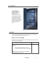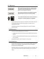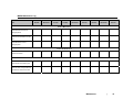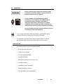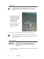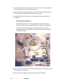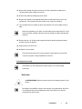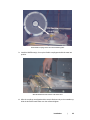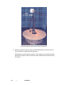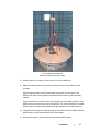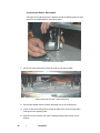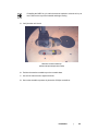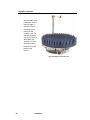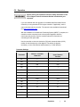
1
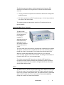
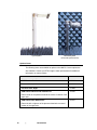
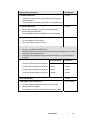
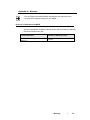
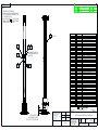
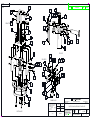
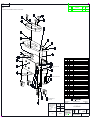
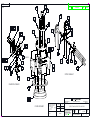
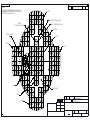
Model 2188 Series
Multi-Axis Positioning System
(MAPS)
User Manual
ETS-Lindgren L.P. reserves the right to make changes to any products herein to improve
functioning or design. Although the information in this document has been carefully reviewed and
is believed to be reliable, ETS-Lindgren does not assume any liability arising out of the
application or use of any product or circuit described herein; nor does it convey any license under
its patent rights nor the rights of others. All trademarks are the property of their respective
owners.
© Copyright 2006–2008 by ETS-Lindgren L.P. All Rights Reserved. No part of this
document may be copied by any means without written permission from
ETS-Lindgren L.P.
Trademarks used in this document: The ETS-Lindgren logo and MAPS are trademarks of
ETS-Lindgren L.P.
Revision Record | MANUAL,MAPS,2188 | Part #399779, Rev. B
Revision
Description
Date
A
Initial Release
July, 2006
B
Revise Assembly Drawing 111040; rebrand
December, 2008
ii
|
Table of Contents
Notes, Cautions, and Warnings ......................................................................... v 1.0 Introduction ................................................................................................... 7 MAPS Models ........................................................................................................................... 7 Model 2110 Light Duty MAPS ...................................................................................... 7 Model 2115 Medium Duty MAPS ................................................................................. 8 Standard Configuration ............................................................................................................. 8 Model 2090 Multi-Device Controller .......................................................................................... 9 Masts ......................................................................................................................................... 9 Optional Items ......................................................................................................................... 10 ETS-Lindgren Product Information Bulletin ............................................................................ 12 2.0 Maintenance ................................................................................................ 13 Routine Maintenance .............................................................................................................. 13 Bi-Annual Maintenance ........................................................................................................... 13 Annual Maintenance ............................................................................................................... 14 MAPS Maintenance Log ......................................................................................................... 15 3.0 Specifications.............................................................................................. 17 MAPS Electrical Specifications ............................................................................................... 17 MAPS Physical Specifications ................................................................................................ 17 Mast Specifications ................................................................................................................. 17 4.0 Installation ................................................................................................... 19 Required Tools ........................................................................................................................ 19 Reference Point ...................................................................................................................... 20 System Installation .................................................................................................................. 20 Anchor Plate Installation ............................................................................................ 21 Upper Drive Unit Removal ......................................................................................... 22 Bore Sight and Leveling .......................................................................................................... 23 Bore Sight .................................................................................................................. 23 Leveling and Height Adjustment ................................................................................ 28 Controller Interface.................................................................................................................. 30 Electrical Interface................................................................................................................... 30 Absorber Installation ............................................................................................................... 32 5.0 Operation ..................................................................................................... 33 Parameter Settings ................................................................................................................. 33 Appendix A: Warranty ...................................................................................... 35 Appendix B: Assembly Drawings .................................................................... 37 Appendix C: EC Declaration of Conformity .................................................... 39 |
iii
This page intentionally left blank.
iv
|
Notes, Cautions, and Warnings
Note: Denotes helpful information intended to provide tips for
better use of the product.
Caution: Denotes a hazard. Failure to follow instructions
could result in minor personal injury and/or property
damage. Included text gives proper procedures.
Warning: Denotes a hazard. Failure to follow instructions
could result in SEVERE personal injury and/or property
damage. Included text gives proper procedures.
See the ETS-Lindgren Product Information Bulletin for safety, regulatory, and
other product marking information.
|
v
This page intentionally left blank.
vi
|
1.0 Introduction
The ETS-Lindgren
Multi-Axis Positioning
System (MAPS™) is
designed to perform
measurements of spherical
antenna patterns as well as
total and effective isotropic
radiated power of wireless
devices. The MAPS provides
independent rotation in both
azimuth and orthogonal
axes.
Medium duty MAPS with optional SAM phantom head
MAPS Models
Three models of MAPS are available. Each model provides a vertical support
column to support the Equipment Under Test (EUT).
MODEL 2110 LIGHT DUTY MAPS
The Model 2110 light duty MAPS can accommodate EUT up to 0.45 kg (1.00 lb),
making it ideal for small devices.
Part Description
Part Number
Model 2110 Light Duty MAPS
Includes:
2110-NNNN
•
•
MAPS Turntable Assembly, part #111040
Light Duty Mast Assembly, part #111046-NNNN
Specify height as –NNNN; for example, 72 inches is
–7200 and 59.5 inches is –5950
Introduction
|
7
Part Description
Part Number
Fiber optic cables, installation hardware, fiber optic
feedthrough connectors
110084
MODEL 2115 MEDIUM DUTY MAPS
The Model 2115 medium duty MAPS is equipped with mounting plates to secure
EUT or a Specific Anthropomorphic Mannequin (SAM) phantom head up to
11.3 kg (25.0 lbs). The SAM phantom head for testing wireless handsets is
optional.
Part Description
Part Number
Model 2115 Medium Duty MAPS
Includes:
2115-NNNN
•
•
MAPS Turntable Assembly, part #111040
Medium Duty Mast Assembly, part #111047-NNNN
Specify height as –NNNN; for example, 72 inches is
–7200 and 59.5 inches is –5950
Fiber optic cables, installation hardware, fiber optic
feedthrough connectors
110084
Standard Configuration
The MAPS includes a horizontal roll axis for mounting EUT. Each MAPS is built
according to the customer-specified height by reducing the vertical support
column to the appropriate length. The height of this axis must be specified when
ordering the unit. A motor drive at the base of the vertical support column, in
conjunction with the ETS-Lindgren Model 2090 Multi-Device Controller (or next
generation ETS-Lindgren controller, if applicable), controls the movement of the
unit.
Each MAPS is furnished with a 63-in (160-cm) diameter circular wood deck that
is bolted onto a motorized turntable. The deck has an opening for the vertical
support and access to the knobs that clamp the sliding carrier into a fixed
position.
The MAPS is equipped with two motor bases, one to control each rotational axis.
A 230 VAC 50 or 60 Hz single-phase receptacle is required to power each unit.
Current draw is less than 4 amps per motor base. The drive power for both
rotations is provided by the filtered 208–230 VAC, 50/60 Hz single-phase power
inside the chamber. Therefore, there is no need for power drive cables to
penetrate the shielded enclosure.
8
|
Introduction
The following steps were taken to minimize potential radio frequency (RF)
obstruction or distortions of RF signals from low-directive wireless transmit
antennas:
•
The use of minimum composite tube materials to fabricate the rotating shaft
and EUT mounts.
•
RF cable connection to the EUT is made through a 1.2-inch hole provided in
the center of the roll axis shaft.
The resultant system test data shows virtually no RF interference from the
light duty MAPS.
Model 2090 Multi-Device Controller
The Model 2090
Multi-Device Controller
(or next generation
ETS-Lindgren
controller, if
applicable) directs the
motor drives for the
upper (phi or x) roll
axis and the rotation of
the turntable (theta or
y axis).
The x-axis motor drive mounts onto a rail system that is attached to the turntable.
This system is positioned on the turntable so that the x-axis centerline projects
through the center of the turntable. The rail system has a sliding carrier that
allows the vertical support assembly to be moved in or out, in a six-inch
(15.2 cm) range, from the center of the turntable. The sliding carrier enables the
movement of the EUT in or out in the same range.
To minimize any potential RF obstruction or distortion of RF signals from
low-directive wireless transmit antennas, each positioning system is provided
with fiber optic control lines that enable the I/O signal between the motor base
and the Model 2090 controller.
Masts
The MAPS mast is a dual-axis angular positioning system capable of rotating the
EUT on the center of both rotation axes with 360° angular span while keeping
the EUT on the center of both rotation axes. The angular accuracy is guaranteed
within ± 0.25° for both axes. The two axes can be controlled independently
through the controller or measurement software
Introduction
|
9
Light Duty Mast
Medium Duty Mast
(shown with optional mount)
Optional Items
The following items are available as options to the MAPS. Custom options are
also available. Contact your ETS-Lindgren sales representative for additional
information on custom options.
Optional Part Description
Part Number
SAM Phantom Head
107182
Phantom Hand, Left
110209
Phantom Hand, Right
110208
SAM Phantom Head Center Rotation Kit
107550
Places center of the phantom head at the center of rotation of the
upper axis
SAM Phantom Ear Rotation Kit
Places the left or right ear of the phantom head at the center of
rotation of the upper axis
10
|
Introduction
107551
Optional Part Description
Part Number
Free-Space Mount Kit
107549
•
•
Light duty free-space mount kit is included with all light duty
mast assemblies
Not compatible with medium duty MAPS 2115 mast assembly
Free-Space Mount Kit
•
•
107559
Medium duty free-space mount kit is not included with
medium duty mast assembly
Not compatible with light duty MAPS 2110 mast assembly
Laptop Mount for medium duty MAPS 2115
•
•
108279
To mount laptop or similar device
EUT rotation axis is at center of EUT
Mounting Adapters for Model 3160 Standard Gain Horn Antennas
• To mount to medium duty MAPS 2115
• Requires antenna mount; also requires an extension to be attached to the rotating
axle of the upper mast assembly
•
If mounting two antennas that require the same extension, only one extension is
required
Antenna Mount
Extension
– 3160-05 Standard Gain Horn Antenna
110758
110759
– 3160-06 Standard Gain Horn Antenna
108416
108793
– 3160-07 Standard Gain Horn Antenna
108417
108793
– 3160-08 Standard Gain Horn Antenna
108418
108793
Dipole Mount Base
107505
CTIA Ripple Antenna Mount Kit
107553-NNNN
•
•
To mount loops and dipoles during the CTIA ripple test
Specify height as –NNNN
For example, 72 inches is –7200 and 59.5 inches is –5950
Introduction
|
11
ETS-Lindgren Product Information Bulletin
See the ETS-Lindgren Product Information Bulletin included with your shipment
for the following:
12
|
•
Warranty information
•
Safety, regulatory, and other product marking information
•
Steps to receive your shipment
•
Steps to return a component for service
•
ETS Lindgren calibration service
•
ETS Lindgren contact information
Introduction
2.0 Maintenance
Before performing any maintenance, follow the safety
information in the ETS-Lindgren Product Information
Bulletin included with your shipment.
Do not perform maintenance while MAPS is operating.
During maintenance, disconnect power for safety.
WARRANTY
Only qualified individuals should conduct maintenance
inspections or perform maintenance on the MAPS.
Regular maintenance will prolong the serviceable life of the turntable. Follow the
recommended schedule and use the log on page 15 to keep a record of
maintenance performed.
If you have any questions concerning maintenance, contact ETS-Lindgren
Customer Service.
Routine Maintenance
Perform the following maintenance prior to each use:
•
Visually inspect the Multi-Axis Positioning System (MAPS) and surrounding
absorber.
•
Attempt to rotate each axis by hand. Excessive rotation may indicate a loose
drive component.
During MAPS operation, listen for excessive or unusual noise.
Bi-Annual Maintenance
Perform bi-annual maintenance every six months after the MAPS is placed into
operation. Prior to maintenance, remove sufficient amounts of absorber to
provide access to the MAPS casters.
Grease the casters every six months or after every 2000 hours of operation. Use
a good quality bearing grease and a standard SAE grease gun to lubricate the
casters.
Maintenance
|
13
Annual Maintenance
Perform the following maintenance every 12 months after the MAPS is placed
into service:
14
•
Use a good quality bearing grease to lubricate the main bearing race. The
grease fittings are located inside the race, 90° apart, under the top. Three
discharges from the grease gun in each fitting are adequate.
•
Use a good quality grease to lubricate the chain and sprocket of the chain
drive.
|
Maintenance
MAPS Maintenance Log
Item
Routine
Bi-Annual
Annual
Routine
Bi-Annual
Annual
Routine
Bi-Annual
Annual
Routine Maintenance
Check absorber for loose or
damaged pieces
Check for excess rotation in each
axis
Check MAPS for loose or
damaged parts
Bi-Annual Maintenance
Grease the casters
Annual Check
Lubricate the main bearing race
Lubricate chain and sprocket and
check tension of the chain drive
Maintenance
|
15
This page intentionally left blank.
16
|
Maintenance
3.0 Specifications
MAPS Electrical Specifications
Nominal AC Voltage:
208–230 VAC
Input Frequency:
50/60 Hz
Current Rating:
10 amp service
Phase:
Single
MAPS Physical Specifications
See the assembly drawings located in the back pocket of the manual for
additional dimensions.
Unit Diameter:
160.02 cm
63 in
Typical Turntable Platform Height:
36.96 cm
14.55 in
Approximate Installed Unit Weight:
453.59 kg
1000 lb
Contact your ETS-Lindgren sales representative for shipping container
dimensions and weight.
Mast Specifications
Mast Type
Mast Height
Maximum EUT Size
Light Duty
(Including free-space mount
part #107549)
Customer-specified
0.45 kg (1 lb)
Within the area of the
provided mount
Medium Duty
Customer-specified
11.3 kg (25 lb)
Within the area of the
optional mount
Specifications
|
17
This page intentionally left blank.
18
|
Specifications
4.0 Installation
Before connecting any components, follow the safety
information in the ETS-Lindgren Product Information
Bulletin included with your shipment.
WARRANTY
Proper installation of the MAPS directly affects
performance. The installation of the MAPS must be
performed by factory installation specialists or
individuals authorized by ETS-Lindgren to perform
installation. This information provided in this manual is
intended to be used only by those installation specialists.
See the assembly drawings located in the back pocket of
the manual to assist with installation.
If you have any questions concerning installation, contact ETS-Lindgren
Customer Service for Customer Service contact information.
The installation of the Multi-Axis Positioning System (MAPS™) will take
approximately eight hours and will require a minimum of two people.
Required Tools
The following tools are required to install the MAPS:
•
Power hand drill, 3/8-in chuck
•
Drill bit, 3/16-in diameter
•
Drive bit, square (provided)
•
Drive bit, #2 Phillips
•
SAE hex key wrench set (maximum 1/2-in)
•
Permanent marker
•
Laser level, 5-beam, and stand
•
Bubble level (36-in minimum)
•
10-in adjustable, open-ended wrench
Installation
|
19
Reference Point
If installing the MAPS in an existing chamber: Remove the absorber from
the floor and lower wall areas prior to installation to avoid damage to the
absorber.
1. Locate the reference point. It
is generally located along the
bore sight axis of the range
antenna. See Bore Sight and
Leveling on page 23 for
additional information
regarding bore sight.
2. With permanent marker, place
an X on the floor of the
chamber at the reference
point.
3. Draw a 47-in (1.19-m) diameter circle to represent the turntable perimeter.
The diameter is larger than the actual perimeter of the circular anchor plates
for the turntable, and should only be used as a guide in centering the turntable
portion of the MAPS.
System Installation
Fiber optic cables must be connected correctly for motor base
function. Before removing fiber optic cables from the
motor base, label the replacement locations for accurate
reconnection.
4. Remove the wood deck. See assembly drawing 110073 located in the back pocket of
the manual for details.
20
|
Installation
5. The MAPS drive units are designed to move from the shipping container to the
chamber floor as a single unit. If you cannot move it as a single unit without causing
damage, separate the upper drive unit. See Upper Drive Unit Removal on page 22.
6. Place on the
chamber floor within
the drawn circle.
When installing the turntable on modular shielding, do not drill anchor holes
through the floor joint strips. Use the shim plates provided.
7. Insert the shim plates to level the turntable over the vault seams.
ANCHOR PLATE INSTALLATION
8. The anchor plates are held in place by 1/4–20 screws and set collars. Screw the
anchor plates to the floor using 14x1 square socket flat head screws.
Drill pilot holes for these screws, and make sure to vacuum shavings to provide good
contact with the floor. Continue mounting the remainder of the plates.
Installation
|
21
9. When all anchor plates are securely mounted, remove the 1/4–20 screws that hold
the anchor plates to the base. Discard the screws.
10. Use a bubble level to verify the turntable unit is flat. This is a preliminary check only;
final leveling of the turntable will be completed in a later step.
11. Use shim plates to level the table. The shim plates will remain in place after the
installation.
UPPER DRIVE UNIT REMOVAL
When installing the MAPS in an existing chamber, it may be necessary to
remove the upper drive unit to avoid damage to the chamber or to the MAPS.
Following are the steps to separate the upper and lower drive units. See
assembly drawings 111040, 109987, and 110073 located in the back pocket of
the manual for details.
12. Prior to disconnecting the fiber optic cables from the upper drive unit, label and mark
the locations for reconnection.
13. Verify the fiber optic cables to the upper motor base are not switched.
22
|
Installation
14. Remove the bracket mounted on the drive unit that is attached to cable carrier.
Two #6 screws hold the bracket to the unit.
15. Remove the cable clip holding the power cable.
16. Remove the bracket on the opposite side of the unit that ties the drive unit to the
turntable top. This temporary bracket holds the unit in place for shipping.
17. Turn the brake knob to release the drive unit and allow it to move toward center of
table.
When the turntable top is in place, use the brake knob to adjust the EUT to the
center of rotation (middle of the quiet zone) by sliding the mast assembly back
and forth.
18. Remove the two 1/4–20 hex head screws that hold the wood top support bracket,
and then remove the bracket.
19. Slide the drive unit carrier out.
20. Reinstall in reverse order.
The brake knob must be in the upper position to allow the drive unit to slide
onto the rail system. Verify all hardware is secured.
Bore Sight and Leveling
If the MAPS unit was ordered with multiple masts, you must bore sight
each mast.
BORE SIGHT
LASER WARNING. Denotes a laser is part of the operating system of the
device.
Bore sight of the MAPS is critical to the accuracy of measurements, and is the
most important step of the installation process. Take the time to verify all
measurements are accurate.
Installation
|
23
To make sure the MAPS is level with the antennas in the chamber and is
accurately centered in the chamber, install the mast(s). Bore sight of the MAPS
requires a five-beam laser level.
Following are the typical installation steps used to achieve bore sight for a MAPS
unit.
1. Locate and mark the center of the chamber wall opposite the range antenna mounted
in the chamber end wall. Marking may require the removal of absorber.
This applies for both rectangular and tapered chambers. In tapered chambers the
antenna is mounted in the far end of the antenna apex. In both cases the typical
installation of the antenna is parallel to the cross section of the opposite end wall.
If the range antenna is mounted elsewhere in the chamber, then the bore sight line
exists normal to the middle of the range antenna.
2. With the laser mounted on a tripod, mark the end of the bore sight line to the end wall
for reference.
24
|
Installation
Fit the flexible couplings of the mast and turntable together
3. Install the MAPS mast(s). Line up the flexible couplings and slide the mast into
position.
Slide the aluminum knobs over the collar of the mast
4. After the couplings are aligned and the mast is fitted securely to the turntable top,
slide the aluminum hand knobs over the collar and tighten.
Installation
|
25
Align laser through the mast mount to the center of the chamber
5. When the knobs are securely in place, place the MAPS system so that the center of
the horizontal axis is aligned with the laser beam.
Small height corrections may be necessary. For information, see Leveling and Height
Adjustment on page 28. After the system is leveled, additional height corrections may
be required.
26
|
Installation
Laser and tripod on turntable top
(Shown with optional dipole mount plate)
6. Mount the laser onto a tripod, and then place it on the turntable top.
7. Sight one horizontal laser in line with the antenna mounted in the end wall of the
chamber.
Align the opposite side of the horizontal laser through the mounting gear of the
MAPS to the center of the opposite end wall and to the reference point previously
marked.
Align the vertical laser with the center of the dipole pole mount plate (optional) or the
MAPS deck to the center axis of the bore sight line. The center of the deck is located
between the two closest screws attaching the plywood deck to the bottom spacers.
8. Verify that the laser beam is visible through the horizontal axis of the MAPS while the
MAPS mast is moved back and forth in the slider system.
9. Achieve bore sight for each mast to be used with the MAPS system.
Installation
|
27
LEVELING AND HEIGHT ADJUSTMENT
If during the bore sight process it is determined that the MAPS system must be
leveled or the height adjusted, follow these steps.
Loosen collar on the anchor shafts
1. Use a 3/16 hex key wrench to loosen the collar on the anchor shafts.
Remove flange nuts, then raise or lower leveling bolts
2. Use an open-ended wrench to loosen the flange nuts on all leveling bolts.
3. Lower or raise the leveling bolts to set the turntable to the correct height. Begin
leveling from two opposing sides.
4. When the level is accurate, move the remaining leveling bolts into the correct
position.
28
|
Installation
If installing the MAPS in a pit, mark the amount required to raise the unit up to
level. Remove the top of the turntable and begin leveling.
5. Verify that the unit is level.
Attach the wooden turntable top
(Shown with optional dipole mount base)
6. Position the wooden turntable top on the turntable base.
7. Use a 5/16 Allen wrench to tighten the bolts.
8. Secure the turntable top seams in place with a Phillips screwdriver.
Installation
|
29
Position the actuating pins on each side of the limit switch access port
9. Verify the access port is located over the limit switch.
10. Position the actuating pins in the holes on each side of the access port.
Controller Interface
For information about connecting fiber optic cables from the MAPS to the
Model 2090 Multi-Device Controller (or next generation ETS-Lindgren controller,
if applicable), see the controller manual.
Electrical Interface
Electrical installation must be performed by a qualified
electrician, and in accordance with local and national electrical
standards.
Only qualified personnel may install the electrical interface
from the chamber to the MAPS.
30
|
Installation
The MAPS is designed to operate using 208–230 VAC single-phase 50 or 60 Hz
power.
The branch circuit supplying power to the motor bases must be protected from
excess current according to local electrical codes. Integral circuit protection is
provided in the motor base assembly.
Check that the conductor size is adequate for the motor load and the distance
from the mains source. Improperly-sized conductors will lead to a high voltage
drop in the power conductors and cause reduced starting torque and premature
motor failure.
The motor base assembly is provided with an IEC-320 power inlet for connecting
to the mains.
Prior to servicing the turntable or the turntable motor base,
remove the power connection for safety.
1. Connect the fiber optic control cable and install the power connection per local
electrical code. See the controller manual for information on connecting fiber optic
cables.
2. After the fiber optic cable is installed, secure it with a wire tie to one of the leveling
screws.
Installation
|
31
Absorber Installation
After the MAPS and
mast(s) are leveled
and bore sight is
achieved, position
the absorber that
surrounds and
covers the unit. For
absorber locations,
see the Top View of
Wood Deck with
Absorber Locations
assembly drawing
located in the back
pocket of the
manual.
Light duty MAPS with deck absorber
32
|
Installation
5.0 Operation
Before placing into operation, follow the safety information in the
ETS-Lindgren Product Information Bulletin included with your
shipment.
If you are unfamiliar with the operation of the Model 2090 Series Multi-Device
Controller (or next generation ETS-Lindgren controller, if applicable), see the
manual included with the controller. The manual is also available for download
from www.ets-lindgren.com.
With the installation of the Multi-Axis Positioning System (MAPS™) complete, the
controller must be connected to the unit and power applied to both the
motor base and controller. See the controller manual for information on
connecting the fiber optic cable.
Use the controller to check the clockwise (CW) and counterclockwise (CCW)
rotation in both directions by a few degrees. The position in degrees
increases (+) in the CW direction and decreases (-) in CCW direction.
Parameter Settings
Parameter
Device 1–Turntable
Theta Axis
Device 2–Mast
Upper Rotation
Phi Axis
P1
0
0
P2
0
0
P3
000
000
P5
1
1
P8
0.1
0.1
P9
8
9
B1
000
000
C
3600
3600
S0
-1
-1
S1
31
31
S2
63
63
S3
95
95
S4
127
127
S5
159
159
Operation
|
33
34
Parameter
Device 1–Turntable
Theta Axis
Device 2–Mast
Upper Rotation
Phi Axis
S6
191
191
S7
223
223
S8
255
255
Ac
2.0
2.0
OC
OFF
OFF
|
Operation
Appendix A: Warranty
See the Product Information Bulletin included with your shipment for the
complete ETS-Lindgren warranty for your MAPS.
DURATION OF WARRANTIES FOR MAPS
All product warranties, except the warranty of title, and all remedies for warranty
failures are limited to two year.
Product Warranted
Duration of Warranty Period
Multi Axis Positioning System
(MAPS™)
2 Years
Warranty
|
35
This page intentionally left blank.
36
|
Warranty
Appendix B: Assembly Drawings
The following assembly drawings are located in the back pocket of the manual:
•
111045
•
109987
•
110073
•
111040
•
111041
•
Top View of Wooden Deck with Absorber Locations
Assembly Drawings
|
37
This page intentionally left blank.
38
|
Assembly Drawings
Appendix C: EC Declaration of Conformity
EC Declaration of Conformity
|
39
REF DRAWING
REVISIONS
NOTES:
1. SEE SHEET 2 FOR DETAILS
2. INSTALL PULLEY ON OUTPUT SHAFT
THAT TURNS IN THE SAME DIRECTION
AS THE INPUT SHAFT
3. MATCH DRILL ITEM 11 AND 12 WITH
.375 BOTH SIDES.
ITEMS 9 AND 10
INSTALL ITEM 15 4 PLACES
48
47
46
45
44
43
42
41
40
39
38
37
36
35
34
33
32
31
30
29
28
27
26
25
24
23
22
21
20
19
18
17
16
15
14
13
12
11
10
9
8
7
6
5
4
3
2
1
ITEM NO.
11 REF ONLY
30
28
39
TRIM BELT TO LENGTH
MATCHDRILL BELT WITH
BRACKETS
29
27
46
46
ECO#
REV
5022
A
4
6
4
.10
1
.01
3
2
4
2
4
2
6
3
18
10
7
1
1
1
1
1
14'
1
3
3
8
3
2
1
1
1
1
4
1
4
1
1
1
1
1
1
2
1
1
1
1
1
QTY.
.67 FROM BOTTOM
OF GEARBOX FLANGE
TO TOP OF COUPLING HUB
X.XX ± .015
X.XXX ± .005
± .5
APPROVALS
DRAWN
RBG
CHECKED
NONE
10/20/05
SEE BOM
DATE
APPROVED
6/28/06
RBG
FLAT WASHER #8 SS .375 O.D. X .032 THK
SCREW, MACH, PH PAHNEAD, 1/4-20 X 1.5
SCREW BINDING HEAD NYLON 10-32 X 1/2
LOCTITE THREAD LOCKING #242 31 50I
ADAPTER,UPPER PULLEY MAPS,2015
EPOXY GRAY ADHESIVE DP-190 3M
SCREW,1/4-20 X 3/4,SLOT,FLAT,NYLON BLK
SCREW SET SOCKET HEAD SS 1/4-20 X 3/8
SCREW, MACH, PHD PHL , 1/4-20 X 3",SST
SCREW,1/4-20 X 1.5,FL HD SLOT,NYLON
NUT,8-32,HEX,SS
SCREW,10-32X.1/4,HEX,SET,SS
SCREW SKTSET 3/8-16 X .75 SS
SCREW,8-32 X 1 3/4,PHIL,PAN,SS
SCREW,1/4-20 X 1-1/4,PHIL,BIND,SS
WASHER SPLIT LOCK SS #8
SCREW,8-32 X 1 1/4,PHIL,PAN,SS
RING,LOCKING,MOUNT,MAST ASSY
BELT CLAMP THRU HOLE,MAPS 2015
BELT CLAMP THREADED, MAPS 2015
TOOTH CLAMP THRU HOLE,MAPS 2015
TOOTH CLAMP THREADED,MAPS 2015
BELT TIMING,A6R4-C050
PULLEY 12T MOD 2015 MAPS
SCREW MODIFIED, WEDGE TIP
SCREW,1/4-20X1/2,SH,CAP,NYLON
SCREW,1/4-20 X 1/2,PHIL,FLAT ,NYLON
MACH SCREW 2-56 X1/4 PHL FLAT HD
BRACE,BEARING TUBE
PULLEY,MODIFIED 2015 MAPS
SHAFT UPPPER
CAP,VERTICAL SUPPORT
BEARING TUBE,UPPER SHAFT
DOWEL PIN 3/8" X 1",MAPS 2015
KEY,HUB,3/16 X 1.20
SCREW,10-32 X 3/4,PHIL,PAN,SST
PLUG,MAST BASE
MAST,MEDIUM DUTY MAPS,.... VERTICAL
BRACKET,RIGHT 2015 MAPS
BRACKET,LEFT 2015 MAPS
GEARBLOCK,MAPS 2015
TOP PLATE,GEARBOX HOUSING,MAST,2115
SIDE PLATE,GEARBOX HOUSING,MAST,2115
HUB,COUPLING,AL,7/8" BORE
ADAPTER,SHAFT,GEARBOX
GEARBOX,WORM,2:1,PRECISION
MOUNT PLATE,GEARBOX MT,2110/2115
MOUNT,BASE,MAST ASSY
DESCRIPTION
ETS LINDGREN
TM
An ESCO Technologies Company
Lindgren-RF Enclosures
Glendale Hts, IL
TITLE
PARTS,COMMON,MEDIUM DUTY MAPS ASSY
PROPRIETARY INFORMATION
MATERIAL
FINISH
DATE
RELEASED
910274
910735
910332
920081
107337
920173
930418
910466
910767
910756
910270
910634
910738
910740
910737
910228
910277
109973
107117
107115
107116
107114
880261
107161
107353
930420
910641
930417
107341
107343
107336
107342
107335
107112
110336
910357
107507
REF ONLY
107345
107344
107108
110306
110307
880302
110303
880271
110305
109970
PART NUMBER
EMC Test Systems, L.P.
Cedar Park, TX
UNLESS OTHERWISE SPECIFIED:
DIMENSIONS ARE IN INCHES
TOLERANCES ARE:
DECIMALS
ANGLES
DESCRIPTION
ANY DUPLICATION OF THIS
DOCUMENT, WHOLE OR IN PART,
WITHOUT EXPRESS WRITTEN
PERMISSION OF ETS LINDGREN
IS PROHIBITED.
SIZE
D
SCALE
1:4
DWG. NO.
DO NOT SCALE DRAWING
REV.
111045
SHEET
1
OF
A
2
REF DRAWING
REVISIONS
40
NOTES:
ECO#
19
10
DESCRIPTION
DATE
APPROVED
21
23
9
REV
42
43
17
44
SEE NOTE 3 15
12
36
24
34
7
16
26
34
18
20
22
11
6
TOP ASSY
45
SEE NOTE 2
32
33
41
38
33
35
33
25
45
2
3
8
32
34
13
31
1
47
45
48
37
4
45
14
45
5
GEARBOX ASSY
UNLESS OTHERWISE SPECIFIED:
DIMENSIONS ARE IN INCHES
TOLERANCES ARE:
DECIMALS
ANGLES
X.XX ± .015
X.XXX ± .005
BOTTOM ASSY
45
± .5
EMC Test Systems, L.P.
Cedar Park, TX
APPROVALS
DRAWN
RBG
CHECKED
NONE
10/20/05
SEE BOM
An ESCO Technologies Company
Lindgren-RF Enclosures
Glendale Hts, IL
TITLE
PARTS,COMMON,MEDIUM DUTY MAPS ASSY
PROPRIETARY INFORMATION
MATERIAL
FINISH
DATE
ETS LINDGREN
TM
ANY DUPLICATION OF THIS
DOCUMENT, WHOLE OR IN PART,
WITHOUT EXPRESS WRITTEN
PERMISSION OF ETS LINDGREN
IS PROHIBITED.
SIZE
D
SCALE
1:2
DWG. NO.
DO NOT SCALE DRAWING
REV.
111045
SHEET
2
OF
A
2
REF DRAWING
REVISIONS
NOTES:
1. DIMENSION IS FROM MOTORBASE COVER TOP TO COUPLING HUB TOP.
18
REV
5068
A
DESCRIPTION
RELEASED
DATE
APPROVED
3/23/06
RBG
27
19
20
21
11
ECO#
9
25
6
1.63
2
15
1.63
SEE NOTE 1
7
31
4
31
30
29
28
27
26
25
24
23
22
21
20
19
18
17
16
15
14
13
12
11
10
9
8
7
6
5
4
3
2
1
ITEM #
13
22
3
24
16 SCREW MUST BOTTOM OUT INTO
ITEM 14, 2X
12
5
34
INSTALL ITEM 30 W/29 AT THIS LOCATION
28
23
10
8
14
1
PART OF LINEAR SLIDE ASSY
SEE ASSY 110073
1
1
3
1
3
1
1
10
6
10
3
3
6
6
16
2
1
1
1
1
1
6
4
6
1
1
2
1
1
1
4
QTY
880301
890687
910159
110747
110765
105012
109980
910664
910393
910762
891020
890694
910777
910437
910136
910801
891016
109975
109979
109977
109967
910386
910447
910441
910931
890912
109978
880302
109040
109984
PART NUMBER
EMC Test Systems, L.P.
Cedar Park, TX
17
UNLESS OTHERWISE SPECIFIED:
DIMENSIONS ARE IN INCHES
TOLERANCES ARE:
DECIMALS
ANGLES
X.XX ± .015
X.XXX ± .005
± .5
APPROVALS
DRAWN
RBG
CHECKED
NONE
SEE BOM
ETS LINDGREN
TM
An ESCO Technologies Company
Lindgren-RF Enclosures
Glendale Hts, IL
TITLE
ASSY,SLIDER,MAPS
7/7/05
PROPRIETARY INFORMATION
MATERIAL
FINISH
DATE
INSERT,SPIDER,92 SHORE A
CABLE CLAMP P-CLIP 1/4" PLASTIC(NOT SHOWN)
SELF TAPPING SCREW PAN HEAD ZN6-32X3/8
MOUNT,CHAIN,CABLE
KNOB,HAND,ALUM,5/16 THRD,MODIFIED
KEY, .187" X .875"
PIN,LOCATING,MAST ASSY
HEX NUT,STAINLESS 1/4-20
WASHER,5/16,LOCK,STL,ZINC,SPLT
LOCKWASHER,SPLIT,1/4:,SS
ROD END,5/16-18 FULL THRD
DOWEL PIN 1/4 X 1.0 SS
SCREW,1/4-20 X 1,SH,CAP,SS
SCREW SOCKET HEAD ALLEN 1/4-20 X 1/2
SCREW ALLEN HEAD 8-32 X .5
SCREW,8-32 X 7/8,SH,GR8
SPRING,WAVE,3/8ID X 9/16OD X .715FL
STOP,SHAFT
SUPPORT,CHANNEL,MOTORBASE MOUNT
SUPPORT,CHANNEL,BRAKE SIDE
RING,MOUNT MAST ASSY
BOLT,5/16-18 X 3/4,HEX,GR5
BOLT,1/4-20 X 1,HEX,SS
BOLT,1/4-20 X 3/4,HEX,SS
SCREW,3/8-16 X 4 1/2,HEX,CAP,SS,FULL THRD
KNOB,3/8 HEX BOLT
MOUNT,BEARING,CHANNEL SUPPORT
HUB,COUPLING,AL,7/8" BORE
ASSY,MOTORBASE,2188
CROSSPLATE,CHANNEL MOUNT
PILLOW BLOCK & BEARING PART OF LINEAR SLIDE ASSY
DESCRIPTION
ANY DUPLICATION OF THIS
DOCUMENT, WHOLE OR IN PART,
WITHOUT EXPRESS WRITTEN
PERMISSION OF ETS LINDGREN
IS PROHIBITED.
SIZE
D
SCALE
1:2
DWG. NO.
DO NOT SCALE DRAWING
REV.
109987
SHEET
1
OF
A
1
REF DRAWING
REVISIONS
NOTES:
1. SOME PARTS SHOWN IN EXPLODED VIEW FOR PART CLARITY.
2. LINEAR SLIDES TO BE SET WITH MOTORBASE ATTACHED TO THEM
FOR PROPER ALIGNMENT AND ADJUSTMENT TO ITEM 3 PRIOR TO
FINAL ASSY.
3. NOT ALL HARDWARE SHOWN.
ECO#
REV
5068
A
DESCRIPTION
RELEASED
DATE
APPROVED
3/23/06
RBG
5
6
17
.38
20
CUT VIEW OF WOOD DECK
VERTICAL SUPPORT AND
THREADED STUD
7
8
15
19
18
3
5
9
25
12
14
4
13
2
10
1
16
17
11
(ON TURNTABLE TOP)
SEE NOTE 2
21
23
24
25
24
23
22
21
20
19
18
17
16
15
14
13
12
11
10
9
8
7
6
5
4
3
2
1
2
2
2
1
1.65
10
35
2
12
.01
12
7
20
8
4
2
1
2
1
1
12
2
1
2
1
910436
910713
910114
891055
891054
910074
910219
107254
109989
920081
910536
110059
910500
910930
910241
109969
109981
109976
109986
109985
109974
880300
109983
880280
108925
ITEM NO.
QTY.
PART NUMBER
UNLESS OTHERWISE SPECIFIED:
DIMENSIONS ARE IN INCHES
TOLERANCES ARE:
DECIMALS
ANGLES
X.XX ± .015
X.XXX ± .005
FINISH
NONE
± .5
APPROVALS
DRAWN
RBG
CHECKED
DATE
SEE BOM
TM
An ESCO Technologies Company
Lindgren-RF Enclosures
Glendale Hts, IL
TITLE
SUB-ASSY,TOP,TURNTABLE,MAPS
5/14/04
PROPRIETARY INFORMATION
MATERIAL
DESCRIPTION
ETS LINDGREN
EMC Test Systems, L.P.
Cedar Park, TX
22
BOLT,1/4-20 X 1/2,HEX,SS
SCREW,4-40 X 1/4" TYPE T,PANHD SELF TAP
MACHINE SCREW FLAT HEAD 4-40 X 3/8
BRACKET,FEMALE,IGUS CHAIN (2 PER PACK)
CHAIN,CABLE CARRIER,IGUS
MACH SCREW FH 1/4-20 X 1.25 SS
WOOD SCREW PHL #6 X 5/8
WOOD DECK STRIP, MAPS
STUD,THREADED,VERTICAL SUPPORT
LOCTITE THREAD LOCKING #242 31 50Ml
SCREW FLAT HEAD SOCKET 1/2-13 X 1-1/2
PLUG,HOLE,TABLE TOP
CAP SCREW SOCKET HEAD SS 8-32 X 5/8
SCREW,10-32 X 3/8.PHIL,FLAT,SS
SCREW FLAT HEAD 8-32 x 3/8
STOP,TRAVEL,CARRIER,MAPS MAST
BRACKET,SUPPORT,WOOD TOP
CROSSBRACE,WOOD DECK
DECK,LOWER HALF,WOOD,MAPS
DECK,UPPER HALF,WOOD,MAPS
SUPPORT,VERTICAL,WOOD DECK
SLIDE,LINEAR,5/8 SHAFT
TOP,TURNTABLE,MAPS
PIN,CLEVIS,SS,1/2"O.D. X 1" LONG
COVER,ACCESS
ANY DUPLICATION OF THIS
DOCUMENT, WHOLE OR IN PART,
WITHOUT EXPRESS WRITTEN
PERMISSION OF ETS LINDGREN
IS PROHIBITED.
SIZE
D
SCALE
1:4
DWG. NO.
DO NOT SCALE DRAWING
REV.
110073
SHEET
1
OF
A
1
REF DRAWING
REVISIONS
NOTES:
1. REFER TO ASSY'S, SUB-ASSY'S, AND KITS FOR OTHER NOTES AND HARDWARE
NEEDED FOR FINAL ASSY AND INSTALLATION REQUIREMENTS.
ECO#
REV
5122
A
5294
5600
DESCRIPTION
DATE
APPROVED
RELEASED
6/28/06
RBG
B
P/N 910159 WAS 910714, UPDATED HW
PER VAULT HARDWARE
4/20/07
RBG
C
ADDED 506179,506180,675319. P/N
910713 QTY WAS 3
12/12/08
RBG
63.00
(WOODEN DECK)
7.80
14.43
5.88
.12 REF
VIEW OF TABLE
FROM MOTORBASE SIDE
22
21
20
19
18
17
16
15
14
13
12
11
10
9
8
7
6
5
4
3
2
1
ITEM NO
2
3
2
13
1
1
1
2
1
.67
7
7
13
1
1
4
5
5
1
1
1
1
1
1
QTY
910714
675319
506180
506179
891073
891072
110809
890748
910159
890166
670027
109533
890817
910246
910713
910436
107561
109968
109982
110073
109987
108912
PART NUMBER
EMC Test Systems, L.P.
Cedar Park, TX
1
UNLESS OTHERWISE SPECIFIED:
DIMENSIONS ARE IN INCHES
TOLERANCES ARE:
DECIMALS
ANGLES
X.XX ± .015
X.XXX ± .005
FINISH
NONE
± .5
APPROVALS
DRAWN
RBG
CHECKED
DATE
SEE BOM
ETS LINDGREN
TM
An ESCO Technologies Company
Lindgren-RF Enclosures
Glendale Hts, IL
TITLE
ASSY,TURNTABLE,MAPS
5/14/04
PROPRIETARY INFORMATION
MATERIAL
SCREW,6-32 X 1/4,PHIL,BIND,TAPTITE
CABLE,HMZD,3X1.50mm2,16A,450/750V (N/S)
FRAME,CONVEX,WHT
RECEPTACLE,UNIVERSAL,FEMALE,WHT,20A,250V
SLEEVING,SLIT CONVOLUTED,PE,3/4" I.D. (N/S)
CLAMP,CABLE,P-CLIP,7/8" (N/S)
BRACKET,HOLD DOWN,SLIDER ASSY
SBR STRIP McMASTER 8510K14 (N/S)
SCREW,6-32 X 3/8,PHIL,BIND,TT
CLAMP CABLE 3/8 8944 HH SMITH 7629 KEYS (N/S)
CABLE,POWER,3 X 16 AWG (N/S)
KIT, MAPS ABSORBER (N/S)
ROTARY JOINT,SMA BULKHEAD,KEVLIN 1102SS
SCREW,8-32 X 1/2,PHIL,FLAT,SS
SCREW,4-40 X 1/4,PHIL,BIND,TAPTITE
BOLT,1/4-20 X 1/2,HEX,SS
ELECTRICAL JUNCTION BOX ASSY,MAPS TT
MOUNT,ROTARY JOINT
PASS THRU,CABLE,TURNTABLE,MAPS
SUB-ASSY,TOP,TURNTABLE,MAPS
ASSY,SLIDER,MAPS
TURNTABLE,ASSY,2188-1.23
DESCRIPTION
ANY DUPLICATION OF THIS
DOCUMENT, WHOLE OR IN PART,
WITHOUT EXPRESS WRITTEN
PERMISSION OF ETS LINDGREN
IS PROHIBITED.
SIZE SCALE
D
1:4
DWG. NO.
DO NOT SCALE DRAWING
REV.
111040
SHEET
C
1
OF
2
REF DRAWING
REVISIONS
ECO#
NOTES:
1.
BRACKET ALONG WITH HARDWARE IS USED TO TIE SLIDER ASSY DOWN PRIOR TO CRATING AND BEFORE SHIPPING.
MOVE SLIDER ASSY INTO POSITION AND APPLY 6-32 SCREWS INTO APPROPRIATE HOLES IN
SLIDER ASSY. APPLY BREAK ON OPPOSITE SIDE TO ENSURE SLIDER ASSY STAYS IN FORWARD
POSITION.
SEE DETAIL B
5
15
REV
DESCRIPTION
8
APPROVED
7
19 20
7
DATE
8
21
CABLE WIRE ENTRY HERE
6
10
BEARING MOUNT PLATE
VIEW OF TABLE
W/O TABLE TOP
VIEW OF TABLE
W/O WOOD TOP
SEE NOTE 1
16
7
14
9
4
DETAIL B
SCALE 1 : 2
SOME PARTS HIDDEN FOR CLARITY
EMC Test Systems, L.P.
Cedar Park, TX
UNLESS OTHERWISE SPECIFIED:
DIMENSIONS ARE IN INCHES
TOLERANCES ARE:
DECIMALS
ANGLES
X.XX ± .015
X.XXX ± .005
± .5
APPROVALS
DRAWN
RBG
CHECKED
NONE
SEE BOM
An ESCO Technologies Company
Lindgren-RF Enclosures
Glendale Hts, IL
TITLE
ASSY,TURNTABLE,MAPS
5/14/04
PROPRIETARY INFORMATION
MATERIAL
FINISH
DATE
ETS LINDGREN
TM
ANY DUPLICATION OF THIS
DOCUMENT, WHOLE OR IN PART,
WITHOUT EXPRESS WRITTEN
PERMISSION OF ETS LINDGREN
IS PROHIBITED.
SIZE SCALE
D
1:4
DWG. NO.
DO NOT SCALE DRAWING
REV.
111040
SHEET
C
2
OF
2
REF DRAWING
REVISIONS
NOTES:
1. SEE SHEET 2 FOR DETAILS
2. INSTALL PULLEY ON OUTPUT SHAFT THAT
TURNS IN THE OPPOSITE DIRECTION OF
THE INPUT SHAFT
16 REF ONLY
12
26
28
12
27
29
TRIM BELT TO LENGTH
MATCHDRILL BELT WITH
BRACKETS
30
ECO#
REV
5022
A
.67 FROM BOTTOM
OF GEARBOX FLANGE TO TOP
OF COUPLING HUB
X.XX ± .015
X.XXX ± .005
FINISH
NONE
± .5
APPROVALS
DRAWN
RBG
CHECKED
DATE
10/10/05
.10
2
2
2
1
2
6
1
4
4
3
10
2
2
4
14
2
1
1
1
1
12.5
2
1
1
1
2
1
1
1
1
1
7
6
4
4
1
1
1
1
2
1
1
1
1
1
920081
890835
910466
930420
110336
910634
910738
107059
910274
910270
910740
910228
910332
910435
910736
910737
910734
107120
107119
107118
107087
880254
107565
107560
107090
109720
880256
107072
107088
109888
REF ONLY
107065
910277
910735
910741
910357
109973
107108
107070
110304
110302
880302
110303
880271
110305
109970
ITEM NO.
QTY.
PART NUMBER
SEE BOM
DATE
APPROVED
6/28/06
RBG
LOCTITE THREAD LOCKING #242 31 50Ml
RUBBER BANDS,BLACK (NOT SHOWN)
SCREW SET SOCKET HEAD SS 1/4-20 X 3/8
SCREW,1/4-20 X 1/2,SH,CAP,NYLON
KEY,HUB,3/16 X 1.20
SKT SET SCREW SS 10-32 X .25
SCREW SKTSET 3/8-16 X .75 SS
NUTBLOCK TUBE BTM,MAPS 2010
FLAT WASHER #8 SS .375 OD, .032 THICK
NUT,8-32,HEX,SS
SCREW,8-32 X 1 3/4,PHIL,PAN,SS
WASHER SPLIT LOCK SS #8
SCREW BINDING HEAD NYLON 10-32 X 1/2
SCREW BINDING HEAD NYLON 1/4-20 X 1/2
SCREW,1/4-20 X 1,PHIL,BIND,SS
SCREW,1/4-20 X 1-1/4,PHIL,BIND,SS
SCREW, BIND HEAD, NYLON, 10-32 X 1 1/4
BRACKET STRAP 4, MAPS 2010
BRACKET STRAP 3, MAPS 2010
BRACKET STRAP 2,MAPS 2010
BRACKET STRAP 1,MAPS 2010
BELT 1/5P X 3/8 LL037XL GATES
SLIDER,ADJUSTMENT,PHONE HOLDER
PHONE HOLDER,2010 MAPS SYSTEM
SHAFT BLOCK,MAPS
COVER,VERTICAL SUPPORT TUBE
BEARING UHMW .75 #57785K27
SHAFT SPACER,MAPS 2010
SHAFT TUBE,MAPS 2010
SUB-ASSY,SHAFT/PULLEY,2010 MAPS
TUBE,VERTICAL SUPPORT,....MAPS
MOUNT,BTM TUBE,MAPS
SCREW,8-32 X 1 1/4,PHIL,PAN,SS
SCREW, MACH, PH PAHNEAD, 1/4-20 X 1.5
SCREW,6-32 X 1/2,PHIL,PAN,SS
SCREW,10-32 X 3/4,PHIL,PAN,SS
RING,LOCKING,MOUNT,MAST ASSY
GEARBLOCK,MAPS 2015
PULLEY 24 T MOD, MAPS 2010
TOP PLATE,GEARBOX HOUSING,MAST,2110
SIDE PLATE,GEARBOX MT,MAST,2110
HUB,COUPLING,AL,7/8" BORE
ADAPTER,SHAFT,GEARBOX
GEARBOX,WORM,2:1,PRECISION
MOUNT PLATE,GEARBOX MT,2110/2115
MOUNT,BASE,MAST ASSY
DESCRIPTION
ETS LINDGREN
TM
An ESCO Technologies Company
Lindgren-RF Enclosures
Glendale Hts, IL
TITLE
PARTS,COMMON,LIGHT DUTY MAPS ASSY
PROPRIETARY INFORMATION
MATERIAL
RELEASED
46
45
44
43
42
41
40
39
38
37
36
35
34
33
32
31
30
29
28
27
26
25
24
23
22
21
20
19
18
17
16
15
14
13
12
11
10
9
8
7
6
5
4
3
2
1
EMC Test Systems, L.P.
Cedar Park, TX
UNLESS OTHERWISE SPECIFIED:
DIMENSIONS ARE IN INCHES
TOLERANCES ARE:
DECIMALS
ANGLES
DESCRIPTION
ANY DUPLICATION OF THIS
DOCUMENT, WHOLE OR IN PART,
WITHOUT EXPRESS WRITTEN
PERMISSION OF ETS LINDGREN
IS PROHIBITED.
SIZE
D
SCALE
1:4
DWG. NO.
DO NOT SCALE DRAWING
REV.
111041
SHEET
1
OF
A
2
REF DRAWING
REVISIONS
31
NOTES:
39
ECO#
APPROVED
21
15
46
DATE
34
32
38
DESCRIPTION
40
17
14
REV
22
2
37
31
35
33
25
18
9
7
44
46
14
35
46
20
8
46
35
SEE NOTE 2
36
16
3
46
41
23
6
46
4
43
19
24
31
42
UPPER ASSEMBLY
5
11
GEARBOX ASSEMBLY
10
13
1
EMC Test Systems, L.P.
Cedar Park, TX
LOWER ASSEMBLY
UNLESS OTHERWISE SPECIFIED:
DIMENSIONS ARE IN INCHES
TOLERANCES ARE:
DECIMALS
ANGLES
X.XX ± .015
X.XXX ± .005
FINISH
NONE
± .5
APPROVALS
DRAWN
RBG
CHECKED
DATE
10/10/05
SEE BOM
An ESCO Technologies Company
Lindgren-RF Enclosures
Glendale Hts, IL
TITLE
PARTS,COMMON,LIGHT DUTY MAPS ASSY
PROPRIETARY INFORMATION
MATERIAL
ETS LINDGREN
TM
ANY DUPLICATION OF THIS
DOCUMENT, WHOLE OR IN PART,
WITHOUT EXPRESS WRITTEN
PERMISSION OF ETS LINDGREN
IS PROHIBITED.
SIZE
D
SCALE
1:2
DWG. NO.
DO NOT SCALE DRAWING
REV.
111041
SHEET
2
OF
A
2
REF DRAWING
REVISIONS
NOTES:
THIS DRAWING REPRESENTS THE LOCATIONS OF
ABSORBER PARTS ON THE MAPS WOODEN DECK.
TO BE USED AS REFERENCE ONLY.
ECN
REV
APPROVED
DATE
DESCRIPTION
110781
109412(LOCATION MAY VARY)
109466
(LOCATION MAY VARY)
109413(LOCATION MAY VARY)
109522(4X)
VERTICAL MAST
REF
109520
109523
109521
109524
WOOD DECK
109524
ITEM#
QTY
PART#
DESCRIPTION
ETS LINDGREN
THIRD ANGLE PROJECTION
110781
TM
An ESCO Technologies Company
UNLESS OTHERWISE SPECIFIED:
DIMENSIONS ARE IN INCHES
REMOVE ALL BURRS AND SHARP EDGES
SURFACE FINISH 63 RMS OR BETTER
TOLERANCES ARE:
DECIMALS
ANGLES
X.XX ± .015
± .5
X.XXX ± .005
FINISH
INITIAL
DATE
DRAFTING
ENGINEERING
RBG
5/23/06
TITLE
TOP VIEW OF WOODEN DECK
W/ABSORBER LOCATIONS
PROPRIETARY INFORMATION
ANY DUPLICATION OF THIS
DOCUMENT, WHOLE OR IN PART,
WITHOUT EXPRESS WRITTEN
PERMISSION OF ETS LINDGREN
IS PROHIBITED.
SIZE
D
SCALE
DWG. NO.
-
NONE
DO NOT SCALE DRAWING
REV.
SHEET
1
OF
1