1
User’s Manual
POS Workstation
Model No.
JS-950 Series
Contents
For USA / For CANADA
English
Read Me First …..….……..... 2
1.Getting Started
2.Operation
3.Appendix
Before operating this product,please read the instructions carefully,
and save this manual for future use.
■ For USA
Federal Communications Commission Radio Frequency Interference Statement
This equipment has been tested and found to comply with the limits for a Class A digital device,
pursuant to Part 15 of the FCC Rules. These limits are designed to provide reasonable
protection against harmful interference when the equipment is operated in a commercial
environment.
This equipment generates, uses and can radiate radio frequency energy and, If not installed
and used in accordance with the instructions, may cause harmful interference to radio
communications. Operation of this equipment in a residential area is likely to cause harmful
interference in which case the user will be required to correct the interference at his own
expense.
This device complies with Part 15 of the FCC Rules. Operation is subject to the following
two conditions: (1) This device may not cause harmful interference, and (2) this device
must accept any interference received, including interference that may cause undesired
operation.
Mercury caution
This product has a fluorescent lamp that contains mercury. Dispose may be regulated in your
community due to environmental considerations. For disposal or recycling information, please
contact your local authorities, or the Electronic Industries Alliance:
http://www.eiae.org
Ce produit possede une lampe fluorescente contenant du mercure. Ceci est a mettre au rebut
selon la regulation locale dans votre communaute en raison des considerations a prendre pour
la protection de l'environnement. Pour obtenir les informations relatives a la mise au rebut ou
au recyclage, veuillez prendre contact avec les autorites locales ou Electronic Industries
Alliance: http://www.eiae.org
Battery
This product contains a CR Coin Cell Lithium Battery which contains Perchlorate
Material-special handling may apply.
See www.dtsc.ca.gov/hazardouswaste/Perchlorate.
■ For CANADA
This Class A digital apparatus complies with Canadian ICES-003.
Cet appareil numérique de la classe A est conforme à la norme NMB-003 du Canada.
1
English
Read Me First
Introduction
Thank you for purchasing the JS-950 series Panasonic POS Workstation.
This manual describes the instructions for the POS Workstation.
Please read this manual carefully before using this product.
List of JS-950 series Product
Name
Model Number.
JS-950WS-040
Main Unit POS Workstation
JS-950WS-050
JS-950D2R010
JS-950D2C020
Display
Touch Display Unit
JS-950D5R010
Unit
JS-950D5C010
JS-950D5C020
Storage
JS-950H35010
Storage module Unit
Unit
JS-950HCF010
MSR Unit
JS-950MG-010
ID module
Dallas Key Reader Unit JS-950DP-010
Unit
Fingerprint Sensor Unit JS-950FS-010
JS-950RD-010
Rear Display Unit
Rear
JS-950RD-020
Display
JS-950SD-010
Unit
2nd Display Unit
JS-950SD-020
JS-950KT-UH0
JS-950KT-UM0
JS-950KT-A10
JS-950KT-E10
AC cord Kit AC cord kit
JS-950KT-F10
JS-950KT-K10
JS-950KT-W10
JS-950KT-Z10
2
Remarks
CPU:3.2GHz,Memory:512MB or 1GB
CPU:3.2GHz,Memory:2GB
12” resistive Touch screen
12” capacitive Touch screen
15” resistive Touch screen
15” capacitive Touch screen
15” capacitive Touch screen
3.5HDD module
Dual CF module
Magnetic stripe reader module
Dallas KEY Reader module
Fingerprint Sensor module
Rear Display module 2line
Rear Display module 4line
2nd Display module 8.4” resistive TP
2nd Display module 8.4” w/o TP
AC cord kit UH
AC cord kit UM
AC cord kit A
AC cord kit E
AC cord kit F
AC cord kit K
AC cord kit W
AC cord kit Z
1. Getting Started
■ Precautions
[POS Workstation: JS-950 series]
IMPORTANT
Install a socket outlet adjacent to the equipment so that it will be easily accessible.
CAUTION
RISK OF EXPLOSION IF BATTERY IS REPLACED BY AN INCORRECT TYPE.
DISPOSE OF USED BATTERIES ACCORDING TO THE INSTRUCTIONS.
1.
Avoid Radio Frequency Interference
Do not place the POS Workstation near a television or radio receiver.
2.
Avoid Stacking
Do not place heavy objects on the POS Workstation.
3.
Keep Small Objects Away
Do not insert paper clips or other small objects into POS Workstation.
There is the risk of heat, fire or explosion.
4.
Keep Dry
There is the risk of heat, fire or explosion.
5.
Do Not Disassemble the POS Workstation
Do not attempt to disassemble the POS Workstation. There is the risk of heat, fire or explosion.
6.
Do Not Touch the Plug with Wet Hands.
There is the risk of electric shock.
7.
Be Certain to Plug Fully Into the Outlet.
There is the risk of electric shock or fire.
8.
When Unplugging, Make Sure to Hold the Body of the Plug.
If the power cord or outlet is damaged, there is a risk of electric shock, short circuit or fire.
9.
Do Not Use a Damaged Power Cord or Plug.
There is the risk of electric shock or fire.
10. Clean the Dust off the Plug, Periodically.
There is the risk of heat or fire.
11. Do not use With Any Other Battery
Please use the specified battery.
CAUTION: Risk of explosion if battery is replced by an incorrect type.
Dispose of used batteries according to the instructions and local requirements.
12. Do not Touch the Power-cord or Plug During a Storm.
There is the risk of electric shock or fire.
13. Do not use the POS Workstation outdoors.
This product assumes the indoor use. There is the risk of breakdown.
14. Do not put the POS Workstation on a slope or an unstable place.
This can cause damage to the unit or injury by falling.
Note:Do not open the Rear cover and Filter cover while the POS Workstation is operating.
3
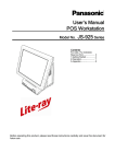
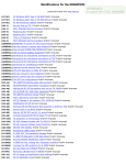
■ Name of each part & function
1
4
2
3
5
6
1. Operator’s Display
2. Front SW cover
3. POP Holder
4. Rear Display
5. USB connector
6. Power SW
Attention: Do not push Power SW by mistake when you insert the USB connector.
4
2. Operation
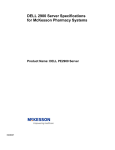
■ AC Cord Kit Installation
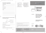
1. How to install the AC Cord
(1) Carefully lay the Main Body Unit on a clear, flat surface as shown in figure (1).
(2) Unpack the AC Cord, and then connect it to AC Inlet as shown in figure (2).
(3) Fit the Cord Clamp to AC Cord, and fix it by attached screw as shown in figure (3)-1, 2 and
3.
(4) Carefully replace the Main Body Unit in upright position as shown in figure (4).
(1)
(2)
(3)-1
(3)-3
(4)
AC Inlet
(3)-2
Note:
3 types of Clampers for fixing AC Cord are enclosed in Carton Box of Main Unit.
Select 1 type of Clamper according to diameter of AC Cord.
Confirm the AC Code doesn't move after fixing the AC Code with the clamper.
Standard Configuration List for AC Cord and Clamper
Model No.
JS-950KT-UH0
JS-950KT-UM0
JS-950KT-A10
JS-950KT-E10
JS-950KT-F10
JS-950KT-K10
JS-950KT-W10
JS-950KT-Z10
Clamper type
PC-3
ø5.6
PC-03C ø6.9
PC-3
ø5.6
PC-03C ø6.9
PC-03C ø6.9
PC-03C ø6.9
PC-03C ø6.9
PC-03C ø6.9
5
■ Display Unit Installation
Be sure to disconnect the power cable of the main block (POS Workstation) and confirm the
power is “OFF” before the operation below.
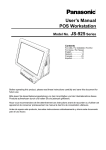
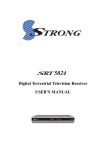
1. How to install the display unit
(1) Open the screw cover of the main unit (POS Workstation).
(2) Hold the display unit with both hands and insert the connector section of the display unit
into the connector inlet guide of the main unit slowly to connect the connector.
Note: When the connector section is connected, do not press the LCD surface of the
display unit.
(Failure to observe this may result in damage to functions of the LCD or touch panel.)
(3) Tighten the 2 thumbscrews of the main unit by hand to secure the display unit.
* Be sure to use hand when tightening the thumbscrews. Hold wire between the tips of
one’s first two fingers as shown in figure (3), and then tighten it.
* Make sure that no looseness is detected when trying to move the display unit.
(4) Close the screw cover of the main unit.
(1)
(2)
(3)
(4)
2. How to replace the display unit
(1) Place the main unit to make the display unit at right angle to the mounting table.
(2) Open the screw cover of the main unit.
(3) Loosen the 2 thumbscrews securing the display unit.
* The thumbscrews shall be loosened until the screws rotate without resistance.
(4) Hold the both sides of the display unit and pull out the unit slowly.
(5) Prepare a new display unit and perform replacement in accordance with the procedure 1,
“How to install the display unit”.
6
■ Storage Unit Installation
Be sure to disconnect the power cable of the main block (POS Workstation) and confirm the
power is “OFF” before the operation below.
1. How to mount the storage unit
(1) Disconnect the 2 latches on the upper portion of the filter cover of the main unit by both
hands, pull the cover toward you while pressing the cover downward at the same time, and
remove the filter cover.
(2) Insert the storage unit into the prescribed inlet of the main unit slowly and connect the
connector of the main unit with the connector of the storage unit.
(3) Tighten the 2 thumbscrews supplied with the main unit by hand to secure the storage unit.
(4) Hitch the lower portion of the filter cover to the main unit, and push the cover until the
latches of both sides on the upper portion are connected to secure the cover.
(1)
(3)
(2)
(4)
2. How to replace the storage unit
(1) Place the main unit to make the display unit in parallel with the mounting table.
(2) Disconnect the 2 latches on the upper portion of the filter cover of the main unit by both
hands, pull the cover toward you while pressing the cover downward at the same time, and
remove the filter cover.
(3) Loosen the 2 thumbscrews securing the storage unit by hand, hold the band on the front
side of the storage unit and pull the band toward you slowly.
(4) Prepare a new storage unit.
Note: Exercise care to avoid any impact to the storage unit(s).
7
■ Rear Display Unit Installation
Be sure to disconnect the power cable of the main block (POS Workstation) and confirm the
power is “OFF” before the operation below.
1. How to mount the rear display unit
(1) Loosen the thumbscrew on the lower portion of the rear cover at the rear display side of the
main unit by hand, and remove the rear cover.
* The thumbscrew shall be loosened until the screw rotates without resistance.
(2) Prepare a rear display to be used. (The contents here explain the 2-line type.)
(3) Connect the hook of the rear display to the hole of the main unit, and tighten the 2
thumbscrews by hand to secure it.
(4) Connect the connector of the rear display with the connector of the main unit.
* The cable connector has a clip to prevent the cable from coming out from the main unit.
(5) Gently press cable toward Display Unit so that it will not extend beyond the case.
In case of installation of 2 line Rear Display module, clamp the cable as shown in the fig.
(5)-1. In case of installation of 4 line Rear Display module, you do not need to clamp cable.
(6) Peel off the blind seal attached on the window of the rear cover.
(7) Attach the rear cover on the main unit, and tighten the thumbscrew on the lower portion by
hand to secure the cover.
(1)-1
(1)-2
(3)-1
(3)-2
(5)-1
(2)
((4)
4)-1
(5)-2
(7)
8
2. How to replace the rear display
(1) Loosen the thumbscrew on the lower portion of the rear cover of the main unit by hand,
and remove the rear cover.
* The thumbscrew shall be loosened until the screw rotates without resistance.
(2) Disconnect the connector of the rear display from the connector of the main unit.
(3) Loosen the 2 thumbscrews securing the rear display, and remove the rear display.
* The thumbscrews shall be loosened until the screws rotate without resistance.
(4) Prepare a new rear display.
(5) Follow the steps (3), (4) and (5) of “How to mount the rear display unit”.
9
■ 2nd display unit Installation
Be sure to disconnect the power cable of the main block (POS Workstation) and confirm the
power is “OFF” before the operation below.
1. How to mount the 2nd Display Unit
(1) Loosen the thumbscrew on the lower portion of the rear cover at the rear display side of the
main block by hand, and remove the rear cover.
* The thumbscrew shall be loosened until the screw rotates without resistance.
(2) Prepare a 2nd display unit to be used. (The contents here explain the 950SD010 type.)
Confirm the wiring that VGA Cable and Speaker Cable are put along case of inside wall as
shown in the fig. (2).
(3) Connect the connector of the 2nd display with the connector of the main block as shown in
fig. (3).
(4) Attach the rear cover on the main block as shown in fig. (4)-1. And also, route the 2nd
display’s cable (950SD010has 2 cables) in the groove as shown in fig. (4)-2. Then, tighten
the thumbscrew on the lower portion by hand to secure the cover.
(5) In case of 950SD010, connect VGA cable and speaker cable to predefined I/F on I/O
panel.
(6) Stand-up correctly.
(1)-1
(1)-2
(2)
(3)-1
(3)-2
(4)-1
(4)-2
(5)
LINE OUT
10
(6)
2. How to replace the 2nd Display Unit
(1) In case of 950SD010, disconnect VGA cable and speaker cable from I/O panel.
(2) Loosen the thumbscrew on the lower portion of the rear cover of the main block by hand,
and remove the rear cover.
* The thumbscrew shall be loosened until the screw rotates without resistance.
(3) Disconnect the connector of the 2nd Display Unit from the connector of the main block.
(4) Prepare a new rear display.
(5) Follow the steps (3), (4) and (5) of “How to mount the 2nd Display Unit”.
11
■ ID module Unit installation
Be sure to disconnect the power cable of the main block (POS Workstation) and confirm the
power is “OFF” before the operation below.
1. Contents
ID module 1pcs
Peripheral screw
2pcs
Screw 2pcs
Cable cover
Long type 1pcs
Short type 1pcs
(Use only
Dallas KEY reader)
Cable clamp 1pcs
2. How to mount the ID module unit (Please see the following pictures.)
(1) Place the main unit to make the display unit at right angle to the mounting table.
(2) Decide which side, right or left, of the display unit the ID module unit is mounted on.
(The contents here explain the case of the magnetic card reader mounting on the right
side.)
(3) Remove Display Unit. See Display Unit Installation.
(4) Remove the 2 screws on the rear side of the display unit using a screwdriver.
After removal of the screws, the peripheral screws can be removed from the front side of
the display unit.
(5) Slide the USB cable cover toward you while pushing both sides of the USB cable cover at
the hinge section of the display unit inward to remove the cover.
(6) Prepare an ID module unit to be mounted.
* The ID module unit is supplied with 2 pieces of peripheral screws, 2 pieces of screws, 1
piece of long cable cover, and 1 piece of short cable cover as accessories. And Dallas
KEY reader is supplied with cable clamp
(7) Handle the cable of the ID module unit (positioning and securing the cable).
・ The guide channel is provided for cable positioning and securing inside the mounting
channel of the ID module unit.
・ The cable shall be run under the ID module unit.
(8) Put the ID module unit in the position where the peripheral screws were removed on the
display unit.
(9) Cable cover has direction as shown in the fig. (9)-1. Insert salient portion of Cable cover to
concave portion of Display unit as shown in the fig. (9)-2 and (9)-3. Then completion
picture is fig. (9)-4.
(10) In case of the magnetic card reader and fingerprint sensor, connect the connector of the
display unit with the connector of those module units.
Secure the cable along the guide channel on the rear side of the display unit as shown in
the fig. (10)-1.
In case of the Dallas KEY reader, secure the cable along the guide channel on the rear
side of the display unit. And loosen a screw as shown in the fig. (10)-2. Use clamp to clip
the ground of USB cable and put it in the position where the screw of fixing LCD hinge
were removed on the LCD hinge. (10)-3.
12
Tighten the screw to clamp the cable and wiring the cable as shown in the fig. (10)-4.
(11) Slide USB cable cover as shown in the fig. (11)-1. In case of Dallas KEY reader, slide the
USB cable cover with care to avoid the cable from the rib of the USB cable cover as shown
in the fig. (11)-2.
(12) Put the supplied 2 peripheral screws in from the front side of the ID module unit and tighten
the screws using a screwdriver from the rear side to secure it.
(13) Install Display Unit according to Display Unit Installation.
(1)
(3)
(5)
(6)
(8)
(9)-1
(4)
Use only
Dallas KEY reader
(7)
(9)-2
Hinge cover side (salient)
(9)-3
(9)-4
(10)-1
(10)-2
(10)-3
(10)-4
13
(11)-1
(11)-2
(12)
Rib
3. How to replace the ID module unit
(1) Remove Display Unit according to Display Unit Installation.
(2) Prepare an ID module unit to be used.
* The ID module unit is supplied with 2 pieces of peripheral screws, 2 pieces of screws, 1
piece of long cable cover, and 1 piece of short cable cover as accessories.
(3) Slide the USB cable cover toward you while pushing both sides of the USB cable cover at
the hinge section of the display unit inward to remove the cover.
(4) Disconnect the connector of the ID module unit from the connector of the main unit, and
detach the cable from the guide channel.
(5) Remove the 2 screws on the rear side of the display unit using a screwdriver.
After removal of the screws, the peripheral screws can be removed from the front side of
the mounted ID module unit.
(6) Perform replacement in accordance with the procedure 1, “How to mount the ID module
unit”.
14
3. Appendix
■ Specifications
[Common Specifications]
Environmental condition
Item
Operating Temperature
Operating Humidity
Strage Temperature
Strage Humidity
Specification
+5°C – +40°C
15% RH – 85% RH (no dew)
-30°C – +60°C
10%RH – 90%RH
[POS Workstation: JS-950WS-・・・ ]
Item
Power Supply input
Size
Mass
Standard
Safty
EMI &
immunity
Specification
AC100V-240V, 50/60 Hz, 6.0A
Approx. W250mm x D277mm x H351mm
Approx. 7.0 kg
cULus, TÜV, CE, GOST, BSMI, SABS
FCC Part15 Class A, ICES-003 Class A, CISPR22 Class A,
CE (EN55022 Class A, EN55024, EN61000), GOST Class A,
BSMI Class A, KCC Class A, C-tick Class A, SABS Class A
1: Power supply cord is not attached.
Please use the AC cord kit in accordance with safety standards in the country of use.
15
IO Connector layout
(1) Bottom IO Connector layout
COM 3
LINE-OUT
(Powered) MIC
Printer
LAN
○○○○○○○○○○○○○
○○○○○○○○○○○○
○○○○○
○○○○
USB1 USB2 COM 1
USB4(+24V)
USB3(+12V)
○○○○○
○○○○
○○○○○
○○○○
○○○○○
○○○○
COM 2
COM 4
(Powered)
(2) Rear Display Connector Layout
○○○○○
○○○○○
○○○○○
C/D1
VGA
C/D2
Top of main block
2nd Display T/P & VFD 4 Lines (COM6)
VFD 2lines (COM6)
(3) Front IO Connector layout SW & LED
USB #5
LAN LED
Soft Switch
HDD LED
Power LED
16
Outside drawing
Main Body
12” Touch Screen
15” Touch Screen
17
[Touch Display Unit: JS-950D・・・・・ ]
Item
Size
Mass
Specification
12.1”: Approx. W320mm x D153mm x H256mm
15”: Approx. W364mm x D153mm x H300mm
12.1”: Approx. 3.4 kg
15”: Approx. 4.4 kg
Outside drawing
(1) 12.1” resistive TP Display, 12.1” capacitive TP Display
(2) 15” resistive TP Display, 15” capacitive TP Display
18
[Storage module Unit: JS-950H・・・・・ ]
Item
Size
Mass
Specification
Approx. W171mm x D126.5mm x H34mm
Approx. 0.8Kg (3.5”), 0.5Kg(2x CF)
Outside drawing
3.5HDD module, Dual CF module
19
[Rear Display Unit: JS-950RD-・・・ ]
Item
Size
Mass
Specification
Approx. W216.5mm x D29mm x H90mm
Approx. 0.4Kg (2 Lines), 0.5Kg (4Lines)
Outside drawing
Rear Display Module 2line, Rear Display Module 4line
Rear Display module 2line
Rear Display module 4line
20
[2nd Display Unit: JS-950SD-・・・ ]
Item
Note:
Size
Mass
Specification
It is not possible to use it together with the Rear Display Unit.
Approx. W250mm x D72mm x H335mm
Approx. 1.4kg
Outside drawing
21
[MSR Unit: JS-950MG-010 ]
Item
accessories
Note:
Size
Mass
Specification
2 pieces of peripheral screws
2 pieces of screws
1 piece of long cable cover
1 piece of short cable cover
MSR, Dallas Key and Fingerprint can not be used at the same
time.
Approx. W63mm x D49mm x H140mm
Approx. 0.1 kg
Outside drawing
22
[Dallas Key Reader Unit: JS-950DP-010 ]
Item
accessories
Note:
Size
Mass
Specification
2 pieces of peripheral screws
2 pieces of screws
1 piece of long cable cover
1 piece of short cable cover
- Work in virtual COM I/F
- MSR, Dallas Key and Fingerprint can not be used at the same
time.
Approx. W73mm x D49mm x H100mm
Approx. 0.15 kg
Outside drawing
23
[Fingerprint Sensor Unit: JS-950FS-010 ]
Item
accessories
Note:
Size
Mass
Specification
2 pieces of peripheral screws
2 pieces of screws
1 piece of long cable cover
1 piece of short cable cover
MSR, Dallas Key and Fingerprint can not be used at the same
time.
Approx. W73mm x D49mm x H100mm
Approx. 0.1 kg
Outside drawing
24
■ Cleaning
Cleaning of outer case
Light soil - Wipe case lightly with a dry, soft cloth.
Heavy soil - Wipe case lightly with soft cloth pre-moistened with very diluted, mild detergent.
Lightly wipe case dry with a dry, soft cloth.
Cleaning of Display
Wipe display gently with a dry, soft cloth to remove light dirt and dust.
Do not wipe or press display hard, hit display or exert force on display as LCD in the display is
breakable.
Do not use OA Cleaner for cleaning it, because it will cause change color or change in quality.
Maintenance of outer case
Outer cases are made of plastic.
Do not apply benzine, thinner, glue, alkalinity detergent, alcohols detergent, glass cleaner, wax,
abrasive cleanser, detergent powder, or pesticide, because it will cause change color or
change in quality. (follow to the cautionary statement if chemical cloth is used.)
Do not leave rubber and vinyl product touched for a long time, because it will cause change
color or change in quality.
Dust filter cleaning
Clean the dust filter every month by mild detergent with the following procedure.
How to remove the dust filter.
(1) Disconnect the 2 latches on the upper portion of the filter cover of the main unit by both
hands, pull the cover toward you while pressing the cover downward at the same time, and
remove the dust filter cover.
(2) Remove the dust filter from rear side of the filter cover with pushing to direction of the
arrow in the figure (2)-1.
(2)-2 Dry dust filter enough after washing.
(3) After dust filter cleaning, reinstall it to rear side of the filter cover as shown in figure (3).
Make sure of 2 raised dots in the holes insuring the dust filter is fixed in place.
(4) Hitch the lower portion of the filter cover to the main unit, and push the cover until the
latches of both sides on the upper portion are connected to secure the cover.
(1)
(2)-1
(3)
(4)
(2)-2
25
■ Operation
Attention for capacitive touch screen
(1) Do not touch it by finger nail, because capacitive touch screen can not recognize it. Touch
it by finger tip.
(2) Do not touch it during startup. It initializes touch screen during startup. If it is touched
during startup, touch screen is not initialized correctly.
(3) Be careful to not accidentally touch around display edges or press on display bezel as it
can negatively affect display touch sensor accuracy.
(4) Touch screen calibration can be affected by atmospheric change - typically great in
magnititude. In case of calibration shifted, perform a calibration adjustment.
(5) Adequacy of touch screen reaction-time or sensitivity may vary by operator. Display
sensitivity can be adjusted by executing a display sensitivity adjustment program*.
(6) Capacitive touch-screen panel uses radio frequency to detect finger tip touch. Terminals
are configured to use different frequencies to avoid conflict in the event of two or more
terminals operating within 1.5 meters (approx. 5') of each other. In the event of conflict
('ghost' or inexplicable touch-screen reaction(s)), shutdown and reboot the terminal to
reselect touch screen frequency.
* Inquire to the supplier about the executing display sensitivity adjustment program.
Carrying/moving terminals
Do not lift or carry the terminal by holding the Display Unit/Unit. Lift and carry the terminal by
securely holding the Main Body Unit from the bottom, with two hands.
Display angle adjustment
Take care not to place the fingers between Display and Main Unit when the angle of Display is
adjusted. Injury may occur. Adjust Display tilt-angle with two hands placed on outside, bezel
edges of Display unit.
26
Specifications and manuals are subject to change without notice.
Microsoft and Windows are registered trademarks of Microsoft Corporation in
the United State of America and other countries.
Intel and Celeron D are trademarks or registered trademarks of Intel
Corporation in the United State of America and other countries.
is a registered of trademark of Panasonic Corporation.
Panasonic System Networks Company of America,
Unit of Panasonic Corporation of North America
Three Panasonic Way,Secaucus,New Jersey 07094 U.S.A.
Panasonic Canada Inc.
5770 Ambler Drive,Mississauga,Ontario,L4W 2T3 Canada
© Panasonic System Networks Co., Ltd. 2010
C0110-0
Printed in China