1
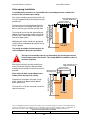
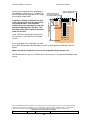
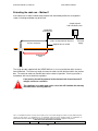
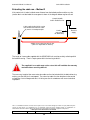
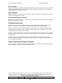
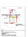
Automatic Bollard User Manual
Genie MkII Installation
INSTALLATION
Unpacking the unit
The GENIE MKII bollard is delivered as a complete assembly. The packing must be carefully
removed and the unit then separated into its two main component parts.
Remove the two countersunk bolts at the top of the bollard assembly and remove the circular lid.
Then remove the retaining screw and the over-ride flap.
Remove the screws which attach the main lid to the outer casing assembly. Raise the lid along
its straight edge and slide it back, disengaging the retention bayonets. The lid may then be lifted
clear of the casing.
The whole assembly should now be lowered into a horizontal position and rested along the flat
edge of the box unit. One person should firmly grasp the top of the inner assembly around the
fixing flange whilst a second supports the inner tube through the bottom of the outer casing.
The inner assembly should now be slid out of the outer casing taking great
care not to damage the hydraulic hoses.
The supplied standard bottom plastic cap or alternative special drainage cap should be fitted
after which the outer casing is ready to be installed into the prepared hole.
Note: If a suitable drain connection is not available drainage holes must be drilled in the
bottom cap to allow water to escape. An adequate soak away must also be created at the
bottom of the excavation.
Preparing the site
A CAT scan of the area must be undertaken before commencing excavation.
A hole will be required in the road surface approximately 500mm by 500mm square and
1100mm deep. Provision should be made for connection to a suitable drain or, alternatively, a
soak-away should be created to ensure that the installation remains clear of standing water.
The top 300mm depth of the hole must be opened out to 700mm diameter.
Ducting is required from the unit to the control unit. Provision is made within the unit for the
entry of a 50mm diameter duct.
The connecting cable carries 240 volts ac and is therefore subject to IEE
regulations. These currently require that mains cables are buried a minimum
of 500mm below the finished road surface and are identified with electrical
marking tape.
This is a confidential document and must not be copied, used, or its contents divulged (in whole or in part) without the prior
consent of ATG Access Ltd. Furthermore use of components other than those permitted herein, or modifications or
enhancements that have not been approved by ATG Access will invalidate the warranty or approval of this product
Hard copies of this document are uncontrolled
Form No: accOMGII
Rev: E
Issue Date: Jan 06
Change: Radio receiver was shown remote.
13