1
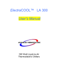
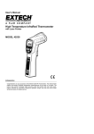
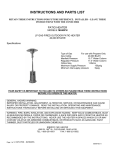
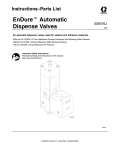
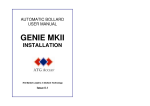
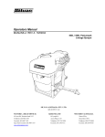
REMOTE VALVE
PNEUMATIC/SNUFF BACK
INSTRUCTIONS / PARTS LIST
Items 1051664, 1051662, 1079254, 1079256
THIS MANUAL CONTAINS IMPORTANT
WARNINGS AND INSTRUCTIONS
READ AND RETAIN FOR REFERENCE
Remote Dispense Valve
HENKEL Corp.
OPERATION / INSTALLATION
OPERATION
INSTALLATION
The ON-OFF operation of the valve is controlled by
movement of the piston inside the air cylinder.
Connect Supply Lines
In the OFF position, the piston retracts and the dual spool
valves (75) seat into the front lip seals (3) which are located
inside the seat plate (8).
The A & B fluid hoses are connected to the side of the valve
body (7), between the valve and the pumps, and should be as
short as possible.
In the ON position, the piston and the spool valves move
forward (75) which allow A & B fluids to pass through the
manifold.
For stationary mount, the air lines will be connected to the
side of the air cylinder. The valve requires air to the front of
the cylinder to close, and air to the back to open. If the
optional handle is used, air is connected to the barbed fitting
on the side of the handle.
To eliminate drooling or stringing of the adhesive out of the
mix tube, the spool valves (75) can be retracted through the
front lip seals (3). This snuff back action is controlled by the
adjustment screw on the back of the air cylinder.
The snuff back should be adjusted so the fluid just stops at
the end of the mixing tube. Excessive snuff back will cause
premature plugging of the valve. Disposable static mixers can
be attached to the manifold.
The air line should have minimum pressure of 80 psi.
Start- Up
With the hand-held model, start metering pumps and purge
the air out of the A & B hoses and Remote Valve. After the A
and B fluids come out of the manifold, attach a mixer to the
manifold and hold the valve upside down with the mixer
pointing up. Dispensing A & B will purge the last pockets of air
in the valve body.
Your REMOTE VALVE in general...
• Designed to dispense two-component adhesives and
sealants.
• Dispenses low or high viscosity urethanes, epoxies and
silicones.
A stationary mount or gantry installation may require removal
from its mount in order to purge. To complete purging, turn
the valve with the mixer pointing up and dispense A & B.
1.
Take a ratio check by weight of A:B after the manifold.
The Remote Valve does No Metering. The Volume Ratio
of A:B is controlled by the metering pumps. However,
between the metering pumps and the Remote Valve are
hoses. These hoses will expand under pressure and
cause lead-lag problems. Lead-lag refers to the uneven
starting of the A fluid before the B fluid. Henkel Corp.
offers standard and high (wide) ratio manifolds to reduce
this problem. The selection of the correct manifold
depends on both the volume and viscosity ratio of A and
B. Consult Technical Services for details at 800LOCTITE.
2.
Adjust snuff back screw for minimum snuff back. Too
much snuff back may draw product into the mixer and
cause curing.
• Can be mounted for beads or timed shots; optional
handle is available for hand held applications.
• Provides an ON-OFF function. The metering of the
adhesives in the proper ratio of A:B is controlled by the
metering pumps.
2
Remote Dispense Valve
HENKEL Corp.
MAINTENANCE
Two-component adhesives are messy and difficult to handle.
It is important to note that Routine Maintenance must be
observed. If one delays maintenance until the valve stops,
clean-up is very time consuming.
ROUTINE MAINTENANCE
1.
Release pressures in A and B fluid hoses. Remove
manifold and clean. We recommend overnight soaking in
a suitable solvent.
2.
At the end of each shift, lubricate the back seals. Pump
grease through the grease fitting (4) and out the plug
(11). Using extra grease will extend seal life
3.
To clean the spool valves (75), first release the pressure
on the A and B fluid hose. Then remove the manifold,
and advance the snuff back adjustment until the spool
valves are protruding from the seat plate (8). With a
toothbrush or rag soaked in solvent, brush the spool
valves clean. Protective eyeglasses should be used.
Note: With moisture sensitive urethanes or epoxies the spool
valves must be cleaned. After cleaning, coat the spool valves
with grease (Reference; Loctite® 997569).
4.
The O-Rings (6) and Lip Seals (3) are in a very harsh
environment. In addition to resisting the adhesives, they
must be inert to the strong solvents used in cleaning the
valve.
3
Remote Dispense Valve
HENKEL Corp.
the back of the valve (facing the air cylinder).
MAINTENANCE
Optional Installation: With O-Ring facing manifold.
Used when minimum snuff back is required. However,
reduced seal life can be expected.
DISASSEMBLY AND CLEANING
1.
2.
3.
Remove the manifold and seat plate (8). Pry bar slots are
provided.
5.
Insert O-Rings and assemble air cylinder and valve body.
Remove the air cylinder bolts (2) and wiggle the air
cylinder apart. If the assembly is frozen, use the pry bar
slots on the valve body (7) to separate the valve body (7)
from the tie plate (5). Insert flat pieces of metal between
the valve body and the tie plate as per Figure 1. Thread
the manifold screws into the back of the tie plate and
push the valve body apart. Apply uniform pressure to
prevent the body from cocking and bending the spool
valves (75).
6.
Push seat plate (8) through spool valves (75) and tighten
bolts.
1.
Check the open and close movement of the spool valves
(75).
Once apart, the parts should be cleaned. We recommend
overnight soaking in suitable solvent. All parts can be
soaked except the handle and air cylinder.
2.
Check gap between seat plate (8) and spool valve (75).
Refer to Figure 2 when spool valves are in open position.
3.
Check front lip seals by pressurizing the valve body (7)
and applying soapy water into the front seals. The valve
body can be pressurized by connecting air into the A and
B inlet ports on the valve body.
4.
Seat Plate (8)
FINAL QC CHECK
Before the manifold is assembled, we recommend the
following procedure:
REBUILDING REMOTE VALVE
1.
After cleaning, inspect the following components:
a.
Spool valves (75) for wear
b.
Lip Seals - both outside and inside lip
c.
Manually retract and extend spool valves from air
cylinder.
d.
If the optional grip handle is used, connect air into
the inlet and check 4-way action of cartridge valve.
2.
Lubricate lip seals and shafts (75) with grease.
3.
Insert four back lip seals: two into tie plate and two into
the valve body. The lip seals are two pieces: an O-Ring
and U-Cup. They should always be installed with the ORing facing the front of the valve (facing the manifold).
4.
Insert two front lip seals (3) that are located in the seat
plate (8). They should be installed with the O-Ring facing
4
Remote Dispense Valve
HENKEL Corp.
MAINTENANCE
TROUBLESHOOTING
Problem _____________________ Cause
No Flow
Manifold clogged
Air pressure too low
Air valve damaged
Spool valves stuck
Valve fouled
Valve Leaks
Snuff back
Spool valve (75) clogged
Seals (3) worn
Spool valve (75) worn
Valve Drools
Air trapped in valve
Seals (3) worn
Off Ratio A:B
Metering pumps
A & B backs up into Tie Plate
Seals damaged
Material not mixing
Fouled Mixer
____________________________ Off Ratio A:B
Mixer Leaks __________________ Manifold Fouled
Lip Seals Deteriorate ___________ Chemical Attack
Solution
Remove manifold and clean
Require 80 psi inlet pressure
See Note 1 below
See Note 2 below
Disassemble (see Maintenance)
Retract snuff back screw
See Note 3 below
Replace seals (see Maintenance)
Inspect and replace if required
Review Start-Up Procedure
Replace Seals (see Maintenance)
Check pumps
Replace Back Lip Seals (page 4)
Replace Mixer
Take Ratio Check
Clean nose of manifold
See Maintenance (page 3)
Note 1. Inspect air cartridge valve in handle. The On-Off
function of the valve is controlled by this cartridge valve in the
handle. The air cylinder requires air in the front to close and
air in the back to open.
To inspect the cartridge valve, disconnect the two air lines on
the air cylinder. When the trigger is depressed, air should be
flowing only through the back air line and not through the front
air line. When the trigger is released the air should reverse.
Note 2. Advance the snuff back screw and pulse air into the
air cylinder. Repeat 3 or 4 times.
Note 3. First release the pressure on the A and B hoses.
Remove the manifold and advance the snuff back screw until
the spool valves are protruding from the seat plate. With a
toothbrush or rag soaked in solvent, brush the valves clean.
After cleaning, depress trigger to retract spool valve.
5
Remote Dispense Valve
Ref.
1
2
3
4
5
6
7A
7B
8
9
10
11
Qty.
1
2
6
2
1
6
1
1
1
2
2
2
*
*
HENKEL Corp.
Description
Single Air Cylinder 5/16" stroke with Hardened SS Valve Shafts
SHCS 10-24 x 2" long
Lip Seal: Polytuff U-Cup and Stainless Steel Spring
Grease Fitting 10-32
Aluminum Tie Plate
Teflon® Encapsulated O-Ring
AlumBody 9/16- 18 Inlet Ports
SS Body 9/16- 18 Inlet Ports
Stainless Steel Seat Plate for
Stainless Steel SHSS 1/4" Dia x 1 1/2" long
Assembled Air Tube and Fitting 10-32 Thread
Plugs: Brass 10-32 with Fiber Washer
* Included in Item 1053257 Valve Repair Kit
Viton® is a registered trademark of DuPont Dow Elastomers Teflon® is a registered trademark of E.I. DuPont De Nemours
6
Remote Dispense Valve
HENKEL Corp.
MANIFOLDS
The Standard Manifold is part of the complete
valve assembly:
The High (wide) Ratio Manifold is part of the
complete valve assembly:
1051664
Aluminum w/ Snuff back
1079254
Aluminum w/ Snuff back
1051662
Stainless w/ Snuff back
1079256
Stainless w/ Snuff back
Threaded Nozzle (3 sizes) Item 1079255
Low viscosity port
High (wide) Ratio Manifold
THIS MANIFOLD TYPE IS USED WHEN THE PRODUCTS
VISCOSITIES VARY GREATLY FROM EACH OTHER. IF
PRODUCT A VISCOSITIY IS 7 TIMES OR GREATER FROM
PRODUCT B (OR VICE-VERSA), THEN A HIGH RATIO
MANIFOLD SHOULD BE USED. THE LOW VISCOSITY
PRODUCT IS FED TO THE THREADED PORT SIDE OF
THE MANIFOLD.
THE HIGH RATIO MANIFOLD HAS A THREADED PORT
TO INSERT 1 OF 3 NOZZLES. THESE NOZZLES REDUCE
THE PRODUCT OUTLET SIZE CAUSING A RESTRICTION
AND THUS INCREASING THE OUTPUT PRESSURE OF
THE PRODUCT AS IT EXITS THE VALVE. THIS HIGHER
PRESSURE PREVENTS THE HIGHER VISCOSITY
PRODUCT FROM FORCING ITSELF INTO THE LOWER
VISCOSITY PORT.
7
Remote Dispense Valve
HENKEL Corp.
GRIP (OPTIONAL; ITEM # 1051661)
8
Remote Dispense Valve
HENKEL Corp.
CONNECTING A MACHINE MOUNTED VALVE TO THE DURAPUMP
Ensure that inlet air and product inlet pressure is OFF
1. Remove the mix-block assembly from the machine.
2. Attach the required product feed hoses to the valve.
3. Remove the valve OPEN and valve CLOSED port plugs on the front of the
machine.
4. Connect a 5/32 air line from the ‘closed’ remote valve port to the closed
pneumatic port on the valve. Do the same for the ‘open’ port.
5. The remote valve will cycle when the footswitch is actuated.
6. To pneumatically cycle the machine, place an air pulse on the Trigger Return
port at the Dispense Valve Connections.
9
Remote Dispense Valve
HENKEL Corp.
CONNECTING A HAND HELD DISPENSE VALVE TO THE DURAPUMP
Ensure that inlet air and product inlet pressure is OFF
1. Connect an air line from the Trigger Supply port on the front of the machine to
the dispense valve’s pilot or constant air supply (single port side on grip
handle).
2. Install a line to the OPEN (A) side of the gun handle. Run the line back to the
Trigger Return port on the machine. Plug the CLOSED port on the handle.
3. Run a line for each; the open and closed ports on the machine to the open
and closed ports on the dispense valve (as illustrated in 5.6).
4. The machine will be cycled by the gun trigger.
This arrangement will permit remote valve operation controlled by the machine
cycling.
Plug this
port
P; Air
Supply
To Trigger
Return
10
Remote Dispense Valve
HENKEL Corp.
AIR CYLINDERS
REMOTE VALVE WITH SNUFF-BACK
Snuff-Back Adjustment: Advancing (clockwise turn) the
snuff-back adjustment screw reduces snuff-back, retracting
(counter-clockwise) it increases the snuff-back. Since
excessive snuff-back action can cause plugging of the valve,
adjust for minimum snuff-back, as follows: with the pumps on
and valve in the “closed” position, advance the adjustment
screw until material begins to drool out of the static mixer
(acting as if the valve is open). Then retract the screw until
fluid just stops, at the minimum snuff-back position. If material
drools or drips during operation, slightly increase the snuffback until the desired action is achieved.
11
Remote Dispense Valve
HENKEL Corp.
SPARE PARTS KITS
Remote Valve Repair Kits
Each Kit contains a complete set of Lip Seals and O-Rings.
Item No. 1053257
Teflon O-Rings
Polytuff U-Cups & SS Springs
Orifice Kit (for High Ratio Valves)
Item No. 1079255 contains:
Description
Polypropylene Fitting .09" Orifice
Polypropylene Fitting .06" Orifice
Polypropylene Fitting .04" Orifice
12
Remote Dispense Valve
Hose Kit (includes elbow fittings to valve and straight
adapters to machine) to 2,250 PSI
Item No.
1051692
1051691
1051693
1051670
1051669
1051664
Description
3/8 x 24” General Purpose
3/8 x 96” General Purpose
3/8 x 144” General Purpose
3/8 x 24” For MMA
3/8 x 96” For MMA
3/8 x 144” For MMA
HENKEL Corp.
ADDITIONAL ACCESSORIES
Ratio Check Cap
In order to ensure correct A/B ratio, ratio checks should be
performed regularly with our new Ratio Check Cap.
Night Cap
316 Stainless Steel 37 Degree JIC Adapters
Item No.
Description
989130
989127
989128
90 degree Elbow with 3/8" Male JIC
Straight Adapter with 1/2" Male JIC
Straight Adapter with 3/8" Male JIC
At night or on weekends, it is a good idea to seal your system.
After the static mixer is removed, a night cap can be installed.
A little grease on the night cap (against the manifold) is also
recommended to enhance the sealing, especially over the
weekends.
Item No.
1053261
1053260
Description
Ratio Check Cap with retaining nut
Night Cap with retaining nut
Hand Held Grip (Pneumatic)
Item No.
1051661
Description
Pistol Grip for Dispense Valve
13
Remote Dispense Valve
HENKEL Corp.
ALL PURPOSE GREASE – APG #2
This Material Safety Data Sheet complies with 29 CFR 1910.1200-OSHA Hazard Communication Standard
SECTION I - PRODUCT IDENTIFICATION
General of Generic ID: Aliphatic Hydrocarbon Gel
DOT Hazard Classification: None
SECTION II - COMPONENTS
If present, IARC, NTP and OSHA Carcinogens and chemicals subject to the reporting requirements of SARA Title III Section 313 are identified in this section.
INGREDIENTS
EXPOSURE LIMITS PERCENT
FOOTNOTE
White mineral oil
PEL-TWA 5 mg/M3
84
(1)
(CAS# 8042-47-5)
TLV-TWA 5 mg/M3
Amorphous fumed silica PEL-TWA 6 mg/M3
12
(CAS# 67762-90-7) TLV-TWA 2 mg/M3
PTFE
Not established
4
(2)
(CAS# 9002-84-0)
(1) OSHA Short Term Exposure Limit (STEL) for mineral oil mist is 5 mg/M3. ACGIII STEL for mineral oil mist is 10 mg/M3.
(2) PTFE - polytetrafluoroethylene fillers and corrosion inhibitors.
SECTION III
PROPERTY
Boiling Point
MEASUREMENT
650°F (component) @ 760 mmHg
Vapor Pressure
Vapor Density
>1 mmHg (component) @ 70°F
Not Available
PROPERTY
Specific Gravity
Percent Volatiles
Evaporation Rate
Appearance
MEASUREMENT
0.8275 (component) @ 77°F
Approximately 84%
Slower than ether
White paste, slight odor
SECTION IV - FIRE AND EXPLOSION INFORMATION
Flash Point:
Explosive Limit:
Extinguishing media:
445°F (component) by TCC
Not available
Dry chemical, carbon dioxide, water spray (fog), regular foam
Hazardous Decomposition Products: May form toxic materials including but not limited to: carbon monoxide, carbon dioxide, various hydrocarbons and trace
amounts of COF2 and CF4 at temperatures above 1200OF.
Fire Fighting Procedures: no special requirements. Wear self-contained breathing apparatus with a full face piece operated in the positive pressure demand mode.
Cool fire exposed containers with water spray.
Special Fire & Explosion hazards: No special requirements.
SECTION V - HEALTH HAZARD DATA
Permissible Exposure Limits: Not established for product. See Section II for PEL/TLVs.
Effects of Acute Overexposure:
EYES: May cause mild irritation. Symptoms may include: stinging, tearing, redness and swelling.
SKIN: May cause mild irritation. Repeated or prolonged contact can dry the skin. Symptoms may include: redness, burning, drying,cracking, and skin burns.
BREATHING: Exposure to vapors or mists is possible. Short-term inhalation toxicity is low. Breathing small amounts incidental to normal handling and use is not
likely to cause adverse effects; however, large amounts may be harmful. Symptoms are associated with exposure that occurs above the recommended exposure
limits. Symptoms may include: Central Nervous Systems (CNS) effects such as: drowsiness, weakness, fatigue, nausea, headache, unconsciousness, coma and
death. Exposure to thermal decomposition products generated by temperatures above 1000OF can cause polymer fume fever, with symptoms of fever, chill, cough
and general malaise. This is generally a temporary condition.
SWALLOWING: Due to the nature of this material, it is difficult to swallow; however, single dose toxicity for each component is considered to be low. Small amounts
swallowed incidental to normal handling and use are unlikely to cause harmful effects, although swallowing large amounts may be harmful. The petroleum based
component in this product is considered an aspiration hazard. During swallowing or vomiting, this material can enter the lungs and cause inflammation and/or
damage. The liquid may also be absorbed through the lungs and result in injury to other body systems.
FIRST AID:
EYES: If symptoms develop, move individual away from exposure and into fresh air. Flush eyes for at least 15 minutes while holding eyelids apart.
SKIN: Remove any contaminated clothing. Wash exposed area with soap and water. If symptoms persist, seek medical attention. Wash any contaminated clothing
before reusing.
BREATHING: If affected, remove individual to fresh air. If breathing is difficult, administer oxygen (if you have been trained in its use). If breathing has stopped, give
artificial respiration. Keep person warm, quiet and get medical attention.
SWALLOWING: Do not induce vomiting. Keep person warm, quiet and get medical attention. If possible, do not leave person unattended.
Aspiration of material into the lungs due to vomiting can cause chemical pneumonitis, which can be fatal.
Primary Route(s) of Entry: Inhalation and skin contact.
Effects of Chronic Overexposure: No data was found on chronic overexposures to this product or its components.
Medical Conditions Aggravated by Exposure: Skin contact may aggravate existing dermatitis or other significant skin conditions.
14
Remote Dispense Valve
HENKEL Corp.
ALL PURPOSE GREASE – APG #2
SECTION VI - REACTIVITY D
ATA
Hazardous Polymerization: Cannot occur.
Stability: Stable
Incompatibility: Avoid contact with strong oxidizing agents, sodium - potassium alloy. Avoid conditions such as: open flame, temperature above 1000°F.
SECTION VII - SPILL OR LEAK PROCEDURES
SMALL SPILL: Vacuum, shovel or sweep up material.
LARGE SPILL: Persons not wearing protective equipment should be excluded from spill area until clean-up has been completed. Only personnel trained in spill
clean-up under 29 CFR 1910.120 should be involved with spill clean-up procedures. Stop spill at source. Prevent material from entering drains, sewers, streams or
other bodies of water. Prevent from spreading. If run occurs, notify appropriate authorities as required. Vacuum, shovel or sweep spilled product to clean containers
for recovery. Transfer contaminated soil and other materials to container for disposal.
Waste disposal: Dispose of in accordance with all local, state, and federal regulations.
SECTION VIII - PROTECTIVE EQUIPMENT TO BE USED
Respiratory Protection: If workplace exposure limit(s) or product or any component is exceeded (See Section II), a NIOSH/MSHA approved air supplied respirator is
advised in absence of proper environmental control. OSHA regulations also permit other NIOSH/MSHA respirators under specified conditions - see 29 CFR
1910.134 or your safety equipment supplier. Engineering and/or administrative controls should be implemented to reduce exposure.
Ventilation: Provide sufficient mechanical (general and/or local exhaust) ventilation to maintain exposure below PEL/TLVs.
Protective Gloves: Wear chemical resistant gloves. Contact your safety equipment supplier.
Eye Protection: Chemical splash goggles in compliance with OSHA regulations are advised. Consult your safety equipment supplier.
Other protective equipment: To prevent repeated or prolonged skin contact, wear impervious clothing and boots.
SECTION IX - SPECIAL PRECAUTIONS OR OTHER COMMENTS
Other Regulatory Information:
CERCLA — Not regulated
RCRA — Not regulated
SARA, Section 302 — Not regulated
SARA, Section 311/312 — Immediate health hazard
SARA, Section 313 — None known to meet the reporting requirements
DOT — Proper shipping name: Not applicable
Hazard Class: Not applicable
Containers of this material may be hazardous when emptied. Since emptied containers retaining product residues, vapors, liquids, and/or solids may pose a hazard.
Containers identified as empty should be handled carefully. Observe all hazard precautions presented on the
MSDS.
The information accumulated herein is believed to be accurate but is not warranted to be whether originating with the company or not.
Recipients are advised to confirm in advance of need that the information is current, applicable and suitable to their circumstances.
15
Remote Dispense Valve
HENKEL Corp.
WARRANTY
Henkel expressly warrants that all products referred to in this
Instruction Manual for Henkel Remote Dispense Valve
(hereafter called “Products”) shall be free from defects in
materials and workmanship. Liability for Henkel shall be
limited, as its option, to replacing those Products which are
shown to be defective in either materials or workmanship or
to credit the purchaser the amount of the purchase price
thereof (plus freight and insurance charges paid therefor by
the user). The purchaser’s sole and exclusive remedy for
breach of warranty shall be such replacement or credit.
WITHOUT LIMITATION OF THE FOREGOING, TO THE
FULLEST EXTENT POSSIBLE UNDER APPLICABLE
LAWS, HENKEL EXPRESSLY DISCLAIMS ANY
LIABILITY WHATSOEVER FOR ANY DAMAGES
INCURRED DIRECTLY OR INDIRECTLY IN
CONNECTION WITH THE SALE OR USE OF, OR
OTHERWISE IN CONNECTION WITH, THE
PRODUCTS, INCLUDING, WITHOUT LIMITATION,
LOSS OF PROFITS AND SPECIAL, INDIRECT OR
CONSEQUENTIAL DAMAGES, WHETHER CAUSED
BY NEGLIGENCE FROM HENKEL OR OTHERWISE.
A claim of defect in materials or workmanship in any
Products shall be allowed only when it is submitted in
writing within one month after discovery of the defect or
after the time the defect should reasonably have been
discovered and in any event, within (12) months after the
delivery of the Products to the purchaser. This warranty does
not apply to perishable items, such as (seals, o-rings, etc.).
No such claim shall be allowed in respect of products which
have been neglected or improperly stored, transported,
handled, installed, connected, operated, used or maintained.
In the event of unauthorized modification of the Products
including, where products, parts or attachments for use in
connection with the Products are available from Henkel, the
use of products, parts or attachments which are not
manufactured by Henkel, no claim shall be allowed.
No Products shall be returned to Henkel for any reason
without prior written approval from Henkel. Products shall
be returned freight prepaid, in accordance with instructions
from Henkel.
NO WARRANTY IS EXTENDED TO ANY EQUIPMENT
WHICH HAS BEEN ALTERED, MISUSED,
NEGLECTED, OR DAMAGED BY ACCIDENT.
EXCEPT FOR THE EXPRESS WARRANTY
CONTAINED IN THIS SECTION, HENKEL MAKES NO
WARRANTY OF ANY KIND WHATSOEVER, EXPRESS
OR IMPLIED, WITH RESPECT TO THE PRODUCTS.
ALL WARRANTIES OF MERCHANTABILITY, FITNESS
FOR A PARTICULAR PURPOSE, AND OTHER
WARRANTIES OF WHATEVER KIND (INCLUDING
AGAINST PATENT OR TRADEMARK
INFRINGEMENT) ARE HEREBY DISCLAIMED BY
HENKEL AND WAIVED BY THE PURCHASER.
THIS SECTION SETS FORTH EXCLUSIVELY ALL OF
LIABILITY FOR HENKEL TO THE PURCHASER IN
CONTRACT, IN TORT OR OTHERWISE IN THE EVENT
OF DEFECTIVE PRODUCTS.
16
Remote Dispense Valve
HENKEL Corp.
Henkel Corporation
1001 Trout Brook Crossing
Rocky Hill, CT 06067-3910
Loctite is a registered trademark of Henkel Corporation, U.S.A
© Copyright 2003. Henkel Corporation. All rights reserved. Data in
this operation manual is subject to change without notice.
Manual P/N: 8901601 Rev A Date: 02/2009
17