1
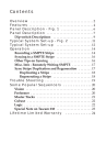
1
24-Bit Flying Calf A/D ™
MANUAL
Version AD20 080699
Table of Contents
FCC Class B and CE Compliance ............................................ 2
Overview ..................................................................................... 2
What’s in the Box? ..................................................................... 3
Features ........................................................................................ 4
Panel Description........................................................................ 4
Front Panel ............................................................................ 4
Rear Panel ............................................................................. 4
Panels - Fig. 1......................................................................... 5
Installation and Typical Setup ................................................. 5
Typical Setup - Fig. 2 ........................................................... 6
Operation .................................................................................... 7
Internal Jumper Settings ........................................................... 9
Location of Internal Jumpers - Fig. 3 ................................ 9
Input Level Jumpers ............................................................ 9
Input Level Jumper Settings (JP2 & JP3) - Fig. 4 ............ 10
Digital Copy-Protect Jumpers .......................................... 10
Copy-Protect Jumper Settings (JP1) - Fig. 5 .................... 10
JP1 Jumper Assignments ....................................................10
Troubleshooting ....................................................................... 11
Specifications ............................................................................ 12
Lifetime Limited Warranty...................................................... 12
FCC Class B and CE Compliance
WARNING: This equipment has been tested and found to comply with the limits for a CLASS B digital device, pursuant to Part 15 of the FCC Rules. These limits are designed to provide reasonable protection against harmful interference in
a residential installation. This equipment generates, uses and can radiate radio
frequency energy and, if not installed and used in accordance with the instructions contained in this manual, may cause harmful interference to radio and television communications. However, there is no guarantee that interference will not
occur in a particular installation.
If this equipment does cause harmful interference to radio or television reception, which can be determined by turning the equipment off and on, the user is
encouraged to try to correct the interference by one or more of the following
measures: 1) reorient or relocate the receiving antenna; 2) increase the separation
between the equipment and the receiver; 3) connect the equipment into an outlet
on a circuit different from that of the receiver; 4) consult the dealer or an experienced audio television technician.
NOTE: Connecting this device to peripheral devices that do not comply with CLASS B requirements or using an unshielded peripheral
data cable could also result in harmful interference to radio or television reception.
The user is cautioned that any changes or modifications not expressly approved
by the party responsible for compliance could void the user’s authority to operate this equipment.
To ensure that the use of this product does not contribute to interference, it is
necessary to use shielded I/O cables.
This product also complies with European CE requirements.
Overview
Thank you for choosing the Flying Calf A/D, professional 24-bit
external A/D converter. The Flying Calf captures incoming audio
with its high-quality Analog-to-Digital (A/D) converters and outputs it digitally via the popular S/PDIF digital audio format. The
Flying Calf is, therefore, the perfect companion for computer digital audio cards, DAT machines, or any other digital audio device
that requires high-quality A/D conversion. Since the Flying Calf
is external, it moves the A/D converters out of the noisy and
2
harsh computer environment. This improves the signal-to-noise
and dynamic range performance dramatically over a typical (or
even professional) sound card.
This manual assumes you have a basic understanding of A/D
conversion and digital audio. If after reading the manual you
need additional tech support, or if you have comments or suggestions, we invite you to contact us directly by any one of the following methods:
MIDIMAN
45 East St. Joseph Street
Arcadia CA 91006-2861
Technical Assistance:
Fax:
Internet Tech Support:
(626) 445-8495
(626) 445-7564
[email protected]
Internet:
Home Page:
http://www.midiman.net
Tech Support E-mail: [email protected]
What's in the Box?
This Instruction Manual
Flying Calf A/D
Power Adapter
Midiman Warranty/Registration Card
IMPORTANT: Please take the time to fill out the included
Warranty Registration Card and mail or fax it to us.
Registering your FLYING CALF A/D will help us to give
you the best possible service and support. Please save all
packing materials in case you ever need to ship the unit.
3
Features
• High-quality, 24-bit stereo, A/D converter.
• Unbalanced analog inputs on independent left and right
1/4” jacks.
• S/PDIF digital output on an RCA connector.
• Transformer-coupled S/PDIF eliminates potential system ground loops.
• Front panel input signal level displays for each channel.
• Jumper-selectable input levels.
• Compact desk-top size: 6.3” x 3.6” x 1.2”.
Panel Description
Front Panel
1. Sample Rate Indicator LED's: Show the current A/D sample
rate (either 44.1 kHz or 48 kHz). These LED's also double as
power indicators – one of the LED's is lit any time the unit’s
power is turned on.
2. Sample Rate Selector Button: Selects the current A/D sample
rate. When this button is out, the sample rate is set to 44.1
kHz. When the button is in, the sample rate is set to 48 kHz.
3. Input Level Displays: These LED display ladders accurately
depict the incoming signal levels at the A/D left and right
channels.
4. Power Button: When this button is in (and the power adapter
is properly plugged in), power is applied to the unit and one
of the Sample Rate Indicator LED's will be lit. When the button is out, the Flying Calf A/D is powered down.
Rear Panel
5. Power connector: For connection to the Calf’s power adapter.
The Flying Calf uses a 9 Volt DC, 500 milliamp (or greater),
center-pin positive supply.
6. Analog In (Left and Right): Analog audio inputs to the
Flying Calf’s A/D converter. These 1/4" jacks accept unbalanced line-level signals. Each jack provides a "tip/sleeve"
type of connection.
4
7. S/PDIF Out: This female RCA jack outputs a standard
S/PDIF digital audio signal. The S/PDIF signal is "stereo,"
containing both left channel and right channel audio data.
The S/PDIF data rate will be determined by the Sample Rate
selector button on the front of the Flying Calf.
Panels - Fig. 1
FLYING CALF A/D ™
224
0 BIT S/PDIF A/D CONVERTER
48
l
R
44.1
- 60 - 20 - 10
-6
-3
CLIP
L
SAMPLE RATE
INPUT LEVEL
POWER
AUDIO
1.
2.
3.
TM
4.
9 VDC
L
5.
ANALOG IN R
S/PDIF OUT
6.
7.
Installation and Typical Setup
Your Flying Calf box should contain this user manual, a power
adapter and the Flying Calf unit itself. Remove the Flying Calf
and power adapter from the box and plug one end of the power
adapter into the Flying Calf's power jack. With the Flying Calf’s
power button in the “out” position (power off), plug the other
end of the power adapter into a wall socket or power strip. Verify
that the Flying Calf and any other devices you plan to connect to
it, are powered off. Now connect your S/PDIF and analog audio
cables to the Flying Calf.
NOTE: For best results, use a good-quality S/PDIF cable. The
cable should be coaxial with 75-ohm impedance. For example, a
good quality video dubbing cable has these characteristics.
5
Typical Setup - Fig. 2
In 4
In 3
In 2
In 1
Line Out
Left
Right
Mixer
S/PDIF
In
DIGITAL AUDIO
CARD
(Inside PC)
S/PDIF
Out
Analog In
Right
Analog In
Left
FLYING
Calf A/D
6
After all connections are made, power up the Flying Calf by
pressing the power button on its front panel.
IMPORTANT: Before powering up the Flying Calf, turn off or
turn down any amplifiers, mixers, or audio converters connected to the Flying Calf's S/PDIF output. Since it may take several
milliseconds for the Flying Calf to output valid S/PDIF, you
may hear a slight "pop" or “buzz” sound while powering up if
you are monitoring the S/PDIF out .
A typical configuration in which a Flying Calf would be used
includes a Calf, a PC-based digital I/O card, a mixer and an
amplifier/sound system. Such a configuration could be setup as
follows: 1.) the stereo line-level audio outs of the mixer goes into
the analog ins of the Calf, 2.) the S/PDIF out of the Calf goes to
the S/PDIF in of the digital audio card, 3.) another audio out of
the mixer may go to an amplifier/sound system or alternately to
an audio out of the audio card can go to an amplifier/sound system.
Operation
The Flying Calf A/D converter accepts analog audio from the left
and right Analog In jacks. These 1/4” audio input jacks expect
unbalanced (tip-sleeve) signals. The analog signals pass through
some analog buffers to the A/D converter, where the audio is digitized at the current sample rate. The A/D converter then drives
the Input Level displays and sends the digitized audio data to the
S/PDIF transmitter. The transmitter formats and outputs the
actual S/PDIF data stream through a transformer to the S/PDIF
Out jack.
The A/D converter always digitizes the analog data at the sample
rate that is set from the front panel of the Flying Calf. When the
Sample Rate select button is in the “out” position, the sample rate
is 44.1 kHz. If the button is in the “in” position, the sample rate is
48 kHz. The current sample rate is always indicated by the front
panel Sample Rate LED's.
7
The level of the analog signal that goes into the Flying Calf should
be adjusted for optimum A/D sampling quality. For best conversion, the input signal should have enough amplitude to take
advantage of nearly all 24 bits of A/D resolution. In other words,
peak levels of the incoming audio signal should be loud enough
to approach the A/D converter's maximum acceptable (full-scale)
signal level. The Flying Calf front panel A/D Input Level indicators aid in this adjustment. Set the level of the audio input signal,
using a mixer or preamplifier device, so that you light as many
level indicator LED's as possible without lighting the red Clip
LED's. When the Clip LED's light, the audio signal is being
"clipped" at the maximum allowable input level of the A/D converter. This may cause extreme distortion and should be avoided.
Note: An occasional CLIP reading is sometimes OK -- it's best to
let your ears be the judge!
The A/D sample rate should be set according to your application's needs. Quite often the sample rate you select will be dictated by the sample rates accepted by other components in the system (such as sound cards, digital audio workstations, CD-ROM
programmers, and DAT machines).
The Flying Calf A/D supports two standard sample rates:
44.1 kHz: Historically, this is the most commonly used sample
rate because it’s the current consumer CD audio sample rate (a.k.a. “redbook audio”). Therefore, audio
captured at 44.1 kHz does not require sample rate conversion in order to be “burnt” to CD-ROM.
48 kHz:
Until recently, this sample rate was reserved for top-ofthe-line professional systems. Today, however, it’s
supported by most computer sound cards and software applications. Compared to 44.1 kHz, 48 kHz will
achieve higher fidelity conversion at the expense of
more storage space per second of recording (if saved to
a disk drive, DAT cartridge, etc.).
8
Internal Jumper Settings
There are four configuration jumpers inside the Flying Calf chassis. Typically you will never need to open the Flying Calf and
adjust these jumpers. For some applications, however, it may be
required. JP2 and JP3 are used to set the input levels for the left
and right channels. JP1 consists of two jumpers which are used to
set the copy-protect status of the Flying Calf.
IMPORTANT: Always power off the Flying Calf and disconnect the power adapter before removing its top.
JP1
Jumper JP1
JP2
JP3
Location of Internal Jumpers - Fig. 3
Jumpers JP3 & JP2
Input Level Jumpers
The Flying Calf A/D factory settings will accommodate audio signals from most line-level devices (which typically have a nominal
signal level of -10 dBV). However, some consumer gear is not
capable of producing enough signal gain to drive the Flying Calf
to full-scale. Therefore, the Calf has internal jumpers which may
be individually set to compensate for these "weaker" devices.
9
Right Analog In
“Standard” Level
Right Analog In
“+6” Level
JP2
Left Analog In
“Standard” Level
JP2
JP3
Jumper JP2 and JP3 Settings
JP3
Jumpers JP2 and JP3 control the
input levels to the LEFT and
RIGHT audio channels, respectively. When set to the
"Standard" position, they
accommodate most signals (-10
dBV nominal). When set to the
"+6" position, they can accept
signals that are 6 dB weaker (-16
dBV nominal). The positions
and settings of these jumpers
are shown in Figure 3 and 4.
Left Analog In
“+6” Level
Input Level Jumper Settings
(JP2 and JP3) -- Fig. 4
Digital Copy-Protect Jumpers
The Flying Calf A/D factory
Jumper JP1 Settings
settings enable SCMS (the
S/PDIF Serial Copy
JP1
JP1
Original
Original
Management System) and the
SCMS
SCMS
digital status is defined as
SCMS Enabled
SCMS Enabled
Original Material
Material is a Copy
"original material from an A/D
Converter." Usually, this will
JP1
JP1
allow all digital data coming
Original
Original
SCMS
SCMS
from the Calf to be accepted by
SCMS Disabled
SCMS Disabled
connected equipment. SCMS
can also be set to "copied material" or it can be disabled all
Copy-Protect Jumper
together. If these settings are
Settings (JP1) -- Fig. 5
preferred, then they may be
selected via the ORIGINAL and SCMS jumpers at jumper block
JP1. The positions and settings of these jumpers are shown in
Figure 3 and 5.
JP1 Jumper Assignments
SCMS
When jumper is installed, SCMS is disabled. When
not installed, SCMS is enabled.
ORIGINAL
If SCMS is not enabled, this jumper does nothing.
10
However, if SCMS is enabled: When ORIGINAL is
installed, data is flagged as a COPY. When ORIGINAL is not installed, data is flagged as ORIGINAL.
Troubleshooting
Symptom: When power is applied, there are no LED's lit on the Flying
Calf's front panel.
Solution: Make sure the power supply is properly plugged into the unit
and into a live wall source or power strip. Also verify that the Calf's
Power button is pushed (and latched) in.
Symptom 1: When first turning the unit on, you sometimes hear small
bursts of noise or a "pop" sound if monitoring the Calf.
Symptom 2: When you change sample rates on the Flying Calf, small bursts
of noise or a "pop" sound are sometimes heard if monitoring the Calf.
Solution: This is normal as it takes a small amount of time for an acceptable
S/PDIF signal to be generated. Be sure to turn down your mixer or amplifier before powering up the Flying Calf or when changing sample rates.
Symptom: Even though an audio signal is being input into the Calf, only
the front panel -60 dB Input Level LED's light (or no Input Level LED's
light).
Solution 1: Check your source signal levels and analog input cables.
Solution 2: The input signal is too weak. Turn up the volume of the audio at
the source and adjust it so that most of the Flying Calf input level LED's
light. Be sure that the clipping level indicators rarely or never light.
Symptom: The front panel Input Level CLIP LED is always lit (or frequently lit).
Solution 1: Check your source signal levels and analog input cables.
Solution 2: The input signal is too strong. Reduce the volume of the source
and adjust it so that the clipping level indicators rarely or never light.
Symptom 1: I can't seem to get a good signal to the A/D when I plug my
Hi-Z microphone into the Analog In(s).
Symptom 2: I can't seem to get a good signal to the A/D when I plug my
Lo-Z microphone (with XLR-line level transformer) into the Analog In(s).
Solution: A microphone preamp (such as the Midiman “Audio Buddy”)
is usually required to boost the microphone signal level to a line-level
that is usable by the Calf.
11
Specifications
Physical Specifications:
Size:
Power Supply:
Approximately 6.3” x 3.6” x 1.2”.
9 volt DC, center-pin positive, 500 ma. or larger.
Audio:
A/D Type:
Sample Rates:
Dynamic Range:
THD + Noise:
Nominal Input Signal:
Full-scale Input Signal:
Frequency Response:
Input Impedance:
Analog In Connectors:
Digital Out Connector:
Digital Out Format:
S/PDIF SCMS:
24-bit, delta-sigma, 128 x oversampling.
48 kHz or 44.1 kHz.
105 dB (A-weighted).
.002%, -94 dB (A-weighted).
-10 dBV (standard input level setting).
-16 dBV (“+6” input level setting).
+6 dBV (standard input level setting).
0 dBV (“+6” input level setting).
24 Hz to 22 kHz (+/- 0.2 dB).
10 K ohms minimum.
1/4” female TS-type, unbalanced.
RCA, female.
S/PDIF, transformer-coupled.
May be enabled or disabled.
Lifetime Limited Warranty
MIDIMAN warrants that this product is free of defects in materials and workmanship under normal
use so long as the product is owned by the original purchaser and that purchaser has registered his/her
ownership of the product by sending in the completed warranty card.
In the event that MIDIMAN receives written notice of defects in materials or workmanship from such
an original purchaser, MIDIMAN will either replace the product, repair the product, or refund the purchase price at its option. In the event any repair is required, shipment to and from MIDIMAN and a
nominal handling charge shall be born by the purchaser. In the event that repair is required, a Return
Authorization number must be obtained from MIDIMAN. After this number is obtained, the unit
should be shipped back to MIDIMAN in a protective package with a description of the problem and the
Return Authorization clearly written on the package.
In the event that MIDIMAN determines that the product requires repair because of user misuse or regular wear, it will assess a fair repair or replacement fee. The customer will have the option to pay this fee
and have the unit repaired and returned, or not pay this fee and have the unit returned unrepaired.
The remedy for breach of this limited warranty shall not include any other damages. MIDIMAN will
not be liable for consequential, special, indirect, or similar damages or claims including loss of profit or
any other commercial, damage, even if its agents have been advised of the possibility of such damages,
and in no event will MIDIMAN’s liability for any damages to the purchaser or any other person exceed
the price paid for the product, regardless of any form of the claim. MIDIMAN specifically disclaims all
other warranties, expressed or implied. Specifically, MIDIMAN makes no warranty that the product is
fit for any particular purpose.
This warranty shall be construed, interpreted, and governed by the laws of the state of California. If any
provision of this warranty is found void, invalid or unenforceable, it will not affect the validity of the
balance of the warranty, which shall remain valid and enforceable according to its terms. In the event
any remedy hereunder is determined to have failed of its essential purpose, all limitations of liability
and exclusion of damages set herein shall remain in full force and effect.
12