1
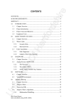
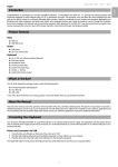
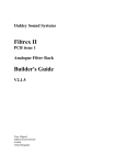
1
Flying Cow ™
MANUAL
version: FC-042799
Table of Contents
FCC Class B and CE Compliance . . . . . . . . . . . . . . . . . . . . . . . .2
Overview . . . . . . . . . . . . . . . . . . . . . . . . . . . . . . . . . . . . . . . . . . . .3
Features . . . . . . . . . . . . . . . . . . . . . . . . . . . . . . . . . . . . . . . . . . . . .4
D/A Converter . . . . . . . . . . . . . . . . . . . . . . . . . . . . . . . . . . . .4
A/D Converter . . . . . . . . . . . . . . . . . . . . . . . . . . . . . . . . . . . .4
Front Panel . . . . . . . . . . . . . . . . . . . . . . . . . . . . . . . . . . . . . . . .4
Panels - Fig. 1 . . . . . . . . . . . . . . . . . . . . . . . . . . . . . . . . . . . . . . . . .5
Panel Description . . . . . . . . . . . . . . . . . . . . . . . . . . . . . . . . . . . . .6
Front Panel . . . . . . . . . . . . . . . . . . . . . . . . . . . . . . . . . . . . . . . .6
Rear Panel . . . . . . . . . . . . . . . . . . . . . . . . . . . . . . . . . . . . . . . .7
Installation and Typical Setup . . . . . . . . . . . . . . . . . . . . . . . . . . .8
Typical Setup - Fig. 2 . . . . . . . . . . . . . . . . . . . . . . . . . . . . . . . . . . .9
Operation . . . . . . . . . . . . . . . . . . . . . . . . . . . . . . . . . . . . . . . . . . .10
Selecting Modes . . . . . . . . . . . . . . . . . . . . . . . . . . . . . . . . . . .10
D/A Operation . . . . . . . . . . . . . . . . . . . . . . . . . . . . . . . . . . .10
A/D Operation . . . . . . . . . . . . . . . . . . . . . . . . . . . . . . . . . . .11
Troubleshooting . . . . . . . . . . . . . . . . . . . . . . . . . . . . . . . . . . . . . .14
Appendix A - Specifications . . . . . . . . . . . . . . . . . . . . . . . . . . . .16
S/PDIF Loopback Test . . . . . . . . . . . . . . . . . . . . . . . . . . . . .17
AES/EBU Loopback Test . . . . . . . . . . . . . . . . . . . . . . . . . . .17
Appendix C - Block Diagram . . . . . . . . . . . . . . . . . . . . . . . . . . .18
Appendix D - Grounding . . . . . . . . . . . . . . . . . . . . . . . . . . . . . .19
Lifetime Limited Warranty . . . . . . . . . . . . . . . . . . . . . . . . . . . . .20
1
FCC Class B and CE Compliance
WARNING: This equipment has been tested and found to comply with
the limits for a CLASS B digital device, pursuant to Part 15 of the FCC
Rules. These limits are designed to provide reasonable protection
against harmful interference in a residential installation. This equipment
generates, uses and can radiate radio frequency energy and, if not
installed and used in accordance with the instructions contained in this
manual, may cause harmful interference to radio and television
communications. However, there is no guarantee that interference will
not occur in a particular installation.
If this equipment does cause harmful interference to radio or television
reception, which can be determined by turning the equipment off and
on, the user is encouraged to try to correct the interference by one or
more of the following measures: 1) reorient or relocate the receiving
antenna; 2) increase the separation between the equipment and the
receiver; 3) connect the equipment into an outlet on a circuit different
from that of the receiver; 4) consult the dealer or an experienced audio
television technician.
NOTE: Connecting this device to peripheral devices that do not
comply with CLASS B requirements or using an unshielded
peripheral data cable could also result in harmful interference to
radio or television reception.
The user is cautioned that any changes or modifications not expressly
approved by the party responsible for compliance could void the user’s
authority to operate this equipment.
To ensure that the use of this product does not contribute to
interference, it is necessary to use shielded I/O cables.
This product also complies with European CE requirements.
2
Overview
Thanks for choosing the Flying Cow, professional external digital
audio converter box. The unit provides high quality, 24-bit A/D
and D/A converters and supports the popular digital audio
formats S/PDIF and AES/EBU. The Flying Cow’s unique design
allows it to fit into half of a standard 19” rack space — two
Flying Cows may be mounted side by side in a single 19” rack
space!
The Flying Cow is a perfect companion for computer digital I/O
cards, or any other digital audio device that requires high-quality
A/D and/or D/A conversion. It can even be used as a
replacement for lower performance DAT or DVD converters.
This manual assumes that you have a basic understanding of
A/D and D/A conversion, and digital audio. If after reading this
manual you need additional technical support or if you have
comments or suggestions, we invite you to contact us directly by
any one of the following methods:
MIDIMAN
45 E. Saint Joseph Street
Arcadia CA 91006-2861
Technical Assistance:
Fax:
Sales:
Internet Tech Support:
(626) 445-8495
(626) 445-7564
(626) 445-2842
[email protected]
Internet:
Web Site:
Tech Support:
Sales Info:
http://www.midiman.net
[email protected]
[email protected]
3
Features
•
•
•
•
•
•
•
•
•
Pro quality, stereo A/D and D/A converters.
Simultaneous A/D and D/A conversion.
Standard single height, half-rack dimensions.
AES/EBU digital I/O on XLR connectors.
S/PDIF digital I/O on RCA connectors.
Balanced analog inputs on either XLR or 1/4”
tip-ring-sleeve connectors.
Unbalanced analog inputs on 1/4” tip-sleeve connectors.
Balanced analog outputs on XLR connectors.
Unbalanced analog outputs on 1/4” connectors.
D/A Converter
•
•
•
•
24-bit stereo D/A, delta-sigma converters with
128x oversampling.
Dynamic range of 104dB (A-weighted).
THD = 0.001% @ 0dBFS.
Frequency Response:† 20Hz-22kHz, -0.5,-0.3dB
A/D Converter
•
•
•
•
•
24-bit stereo A/D, delta-sigma converters with
128x oversampling.
Dynamic range of 102dB (A-weighted).
THD: 0.0015% @ 0dBFS.
Frequency Response:† 20Hz-20kHz, -0.5,-0.3dB.
Sample Rates:† 32, 44.1, 48 kHz and "EXT".
Front Panel
•
•
•
•
•
•
Analog Input Level knob allows optimum gain setting of
input signal to A/D.
Dual LED level ladders accurately depict incoming signal
levels to A/D.
A/D sample rate adjustable from front panel.
“D/A Valid” LED indicates valid incoming digital data.
LEDs indicate current digital format and A/D sample rate.
Unit remembers system setup even after power-off.
4
9VAC
8.
AUDIO
D/A
VALID
R
1.
5
S/P
DIF
9.
2.
ANALOG OUT
AES/
EBU
DIGITAL
FORMAT
1
L
48
44.1 32
3.
EXT
A/D
SAMPLE RATE
R
L
5.
-3
11.
AES /E BU
OUT
CLIP
A/D INPUT LEVEL
- 40 - 20 - 10 - 6
10.
4.
R
L
ANALOG IN
MODE
SELECT
IN
OUT
0
S/PDIF
12. 13.
6.
MAX
ANALOG
INPUT LEVEL
7.
14.
AES /E BU
IN
POWER
24 BIT FLYING COW™
Panels - Fig. 1
Panel Description
Front Panel
1. D/A Valid: This LED indicates valid incoming digital data
for the D/A converter. When in AES/EBU mode, this LED
lights whenever there is a valid digital signal present at the
AES/EBU In jack. When in S/PDIF mode, this LED lights
whenever there is a valid digital signal present at the S/PDIF
In jack.
2. Digital Format: These two LED’s indicate the current digital
interface mode as either AES/EBU (professional) or S/PDIF
(consumer). The mode applies to digital data both entering
and exiting the Flying Cow. The Digital Format is selected
via the Mode Select Button.
3. A/D Sample Rate: These four LED’s indicate the current
sample rate in use by the A/D converter (48kHz, 44.1 kHz, 32
kHz, or EXT). The first three are standard sample rates. EXT
is a special mode in which A/D conversion is synchronized
with the sample rate of some external source. It is often used
to sync with less common and non-standard sample rates.
4. Mode Select: Repeatedly pressing this button will cycle
through all of the available sample rates and digital formats.
When powered up, the Flying Cow will restore the mode and
sample rate that was set before the previous power-down.
5. A/D Input Level LED’s: These LED meters indicate the left
and right analog audio levels entering the A/D converter.
CLIP indicates an overload condition to the A/D channel and
will result in distortion.
6. Analog Input Level: This knob sets the level of the incoming
analog audio signal as it enters the A/D converter. For the
greatest dynamic range (and signal-to-noise ratio), it is best to
set these levels as high as possible without making the CLIP
LED’s light. When turned all the way down (0) attenuation is
full, and when turned all the way up (Max) gain is maximum.
7. Power: When this button is in, power is applied to the unit.
When out, power is off. When power is turned off, the
Digital Format and A/D Sample Rate settings are saved, and
restored upon power up.
6
Rear Panel
8. Power connector: For connection to the unit’s external “wallwart” power supply. The Flying Cow uses an external 8.5 or
9 volt A/C power supply with 1 amp or greater current
capacity.
9. Analog Out (Right and Left): These are the analog audio
outputs from the Flying Cow’s D/A converters. These
unique combination jacks mate with either male XLR-type
connectors or 1/4” phone plugs. The XLR (outer) portions of
the jacks provide balanced outs. The 1/4” (inner) portions
provide unbalanced outs.
10. Analog In (Right and Left): These are the analog audio
inputs to the Flying Cow’s A/D converters. These unique
combination jacks mate with either male XLR-type connectors
or 1/4” phone plugs. The XLR (outer) portions of the jacks
are compatible with balanced inputs. The 1/4” (inner)
portions are compatible with both balanced (tip-ring-sleeve)
and unbalanced (tip-sleeve) inputs.
11. AES/EBU Out: This male XLR jack provides standard
AES/EBU digital output from the Flying Cow’s A/D
converters. The digital audio signal is stereo, containing
both left and right channel data.
12. S/PDIF In: This female RCA jack accepts standard S/PDIF
input to the Flying Cow’s D/A converters. The digital audio
signal is stereo, containing both left and right channel data.
This jack may also be used to accept S/PDIF “Word Clock” to
the Flying Cow when operating with EXT sample rate.
13. S/PDIF Out: This female RCA jack provides standard
S/PDIF digital output from the Flying Cow’s A/D converters.
The digital audio signal is stereo, containing both left and
right channel data.
14. AES/EBU In: This female XLR jack accepts standard
AES/EBU input to the Flying Cow’s D/A converters. The
digital audio signal is stereo, containing both left and right
channel data. This jack may also be used to accept AES/EBU
“Word Clock” to the Flying Cow when operating with EXT
sample rate.
7
Installation and Typical Setup
Your Flying Cow box should contain this manual, a “wallwart”
power transformer (U.S. customers only) and the Flying Cow
unit itself. Please save all packing materials in case you should
ever need to ship the unit.
The Flying Cow may be operated on any flat surface or it may be
installed in a standard 19” rack equipment tray. For installation
in a 19” rack tray you will first need to remove the four rubber
feet from the unit. Next, left or right justify the Flying Cow in
the rack tray. Lastly, tighten the included rack-mount screw,
through the rack tray hole, into the single threaded hole on the
bottom of the Flying Cow chassis.
Plug in the power supply. With the Flying Cow’s power turned
off, make your connections to any analog or digital cables you
will be using. Next, power up the Flying Cow by pressing the
Power button on the front panel.
IMPORTANT: Before powering up the Flying Cow, turn down
any amplifiers (or mixers) connected to the Flying Cow’s outputs.
Since it takes several milliseconds for the Flying Cow to acquire
and lock onto an incoming digital signal, there may be a slight
“pop” sound while powering up.
A typical configuration in which a Flying Cow would be used
includes a Flying Cow, a PC based digital I/O card, a mixer and
an amplifier/sound system (see Typical Setup figure). Such a
configuration could be setup as follows: 1.) the unbalanced stereo
audio out of the mixer goes to the 1/4” audio inputs on the
Flying Cow, 2.) the S/PDIF out of the digital audio card goes to
the S/PDIF In on the Flying Cow, 3.) the S/PDIF in of the digital
audio card goes to the S/PDIF Out on the Flying Cow, 4.) the
unbalanced Analog Out on the Flying Cow goes to a line level
audio in on the amplifier/sound system.
8
Typical Setup - Fig. 2
MIC 1
MIC 2
IN 1
IN 2
3 mon
5L mon
7L mon
9L mon
OUT L
OUT R
4 mon
6R str
8R str
10R str
STR RET
SEND
RIGHT
LEFT
SPEAKERS
1
2
HIGH
•
•
•
•
-15
•
•
•
•
•
•
•
•
•
+15
•
-15
•
-15
•
•
•
+15
•
0
•
•
•
+6
-15
R
•
•
•
•
•
•
+6
00 +20
•
-15
•
•
•
•
0
R
•
•
•
•
•
•
+6
00 +20
•
00
•
•
•
•
Max
POWER
•
•
•
MI
+15
•
•
•
•
-15
•
•
•
+15
SEND
•
•
•
•
0
•
•
•
+6
R
•
•
•
00 +20
•
SEND
R
•
•
•
•
•
0
•
•
•
+6
SEND
•
•
•
00 +20
•
0
TM
+8
0
•
•
R
•
•
•
00 +20
- 20
R
GAIN
•
•
•
PHONES
•
L
GAIN
•
POWER
AMP
CLIP
•
•
•
+6
BAL
•
L
•
•
•
•
•
•
•
•
GAIN
10
7/8
BAL
•
L
•
•
•
XI M
10 CHANNEL MIXER
5/6
•
GAIN
•
+15
•
-15
PAN
•
L
•
•
•
•
•
•
LOW
+15
RIGHT
TAPE OUT
STEREO RTN
•
•
•
MID
SEND
•
•
•
•
-15
•
GAIN
•
•
•
•
PAN
•
L
•
•
•
•
•
•
+15
•
•
•
•
•
GAIN
•
•
•
•
•
•
•
•
+15
•
-15
PAN
•
L
-15
TAPE IN
HIGH
•
•
•
LOW
+15
0
•
MID
SEND
•
•
•
•
•
•
•
•
+15
•
•
•
•
PAN
•
•
•
•
•
•
+15
•
-15
LOW
SEND
•
•
•
•
•
•
LEFT
4
HIGH
•
•
•
MID
+15
LOW
•
•
•
•
-15
MID
•
•
•
3
HIGH
•
•
•
•
•
•
•
MAIN
•
•
•
•
•
•
•
00 Max
00 +20
MIXER
S/PDIF
Out/In
DIGITAL AUDIO
CARD
(Inside PC)
S/PDIF
In/Out
AUDIO
In
AUDIO
Out
FLYING
COW
9
Operation
The A/D and D/A sections of the Flying Cow operate
simultaneously, even though you may sometimes choose to use
only one or the other at any given time. The A/D and D/A are
both set up from the Flying Cow’s front panel.
Selecting Modes
The Mode Select button is used to select the A/D Sample Rate
and the Digital Audio Format. As the Mode Select button is
repeatedly pressed, the Flying Cow cycles between the four
Sample Rate settings: 48 kHz, 44.1 kHz, 32 kHz, and EXT. After
every four presses of the button the Digital Format will also
change — between AES/EBU and S/PDIF settings. Therefore, it
should never take more than 8 presses of the button to get to
your desired setup.
As they are changed, the Sample Rate and Digital Format settings
are stored inside the Flying Cow. When the Flying Cow is turned
off and then back on, these changed settings will be retained.
D/A Operation
The Flying Cow D/A converter is compatible with 24bit, 20bit,
18bit, and even 16bit digital data — the more bits per data word,
the better the dynamic range of the output signal — and
therefore, the better the audio quality. The D/A converter
receives a continuous digital audio stream from either the
AES/EBU In or S/PDIF In jack, depending on the setting of the
Digital Format on the Flying Cow’s front panel. The digital data
is converted to stereo analog audio, and output through the left
and right Analog Out jacks. The Analog Out jacks can accept
either XLR connections or 1/4” connections. On the XLR audio
out connections, the audio is balanced; on the 1/4” audio out
connections, the audio is unbalanced.
The D/A does not require you to manually select a sample rate.
Instead, it automatically detects the sample rate of the incoming
digital audio data and adjusts it accordingly. If a valid digital
stream is detected, the front panel “D/A Valid” LED will light.
10
IMPORTANT: For the Flying Cow D/A converter to work properly,
the Digital Format must be set to the correct incoming digital format
(AES/EBU or S/PDIF).
A/D Operation
The Flying Cow A/D converter accepts analog audio from the left
and right Analog In jacks, using either XLR or 1/4” connections.
The XLR audio input connections accept balanced signals. The 1/4”
audio input connections accept either balanced (tip-ring-sleeve) or
unbalanced (tip-sleeve) signals. The analog signals then pass
through the Analog Input Level control and into the A/D converter
as balanced signals. Finally, the A/D converter converts the analog
data to a digital data stream and outputs it to both the AES/EBU
Out and S/PDIF Out jacks simultaneously.
IMPORTANT: The same digital data is always present at both the
AES/EBU and S/PDIF output jacks. Electrically, both of these
signals will always be correct. However, the data format of the
audio stream will be correct on one jack but not the other (the data
format will match the Flying Cow’s front panel Digital Format
setting). In many applications this will not present a problem.
However, if it does, you must set the front panel Digital Format to
match the digital output standard you will be using.
The A/D converter requires three parameters to be set up for proper
operation: Digital Format, Input Level, and Sample Rate.
From the front panel controls of the Flying Cow, set the Digital
Format to match that of the digital output jack of the external
equipment to which you are connecting the Flying Cow (see page
10–Selecting Modes). For example, if you are connecting the Flying
Cow S/PDIF Out to the S/PDIF In of a PC digital sound card, set
the Digital Format to S/PDIF.
Input Level should be adjusted for optimum A/D sampling quality.
For best conversion, the input signal should have enough amplitude
to take advantage of all 24 bits of A/D resolution. In other words, the
incoming audio signal should be loud enough to approach the A/D
converter’s maximum acceptable (full-scale) signal level. The Analog
Input Level adjustment on the Flying Cow’s front panel allows you to
attenuate or amplify an incoming signal to properly attain the
11
optimum A/D input level. The Flying Cow front panel A/D Input
Level indicators aid in this adjustment. Set the A/D input level
knob so that you light as many level indicator LED’s as possible
without lighting the red Clip LED’s. When the Clip LED’s light,
the audio signal is being “clipped” at the maximum allowable
input level of the A/D converter. This may cause extreme
distortion and should be avoided.
NOTE: For the absolute best results, set the Analog Input Level to
full attenuation (“0” setting) and externally adjust the incoming
analog signals to reach the -3 dB levels at peak volume. An
occasional CLIP reading is sometimes OK — it’s best to let your
ears be the judge!
The A/D Sample Rate should be set according to your
application’s needs (see page 10–Selecting Modes). The higher the
sample rate, the better the audio quality. On the down side, the
higher the sample rate, the more digital data has to be stored per
second. Quite often, the sample rate you select for the Flying Cow
will be dictated by the sample rates accepted by other components
in the system such as sound cards, digital audio workstations, CD
players, and DAT machines.
The Flying Cow supports three standard sample rates:
48 kHz:
In the past, this sample rate was reserved for the most
costly professional systems. Today it’s even supported
by computer sound cards and many software
applications. 48 kHz will achieve the highest fidelity
conversion at the expense, however, of requiring more
storage space per second of recording (if saved to a
disk drive, DAT cartridge, etc.).
44.1 kHz: Historically this has been the most commonly used
sample rate because it is the current consumer CD
audio sample rate (a.k.a. “redbook audio”). It strikes a
good balance between sound quality and storage
requirements.
32 kHz:
Used for lower-fidelity conversion and utilized mostly
in applications that have limited storage space.
Frequency response is similar to a mid-priced cassette
deck, but signal-to-noise ratio is much higher than any
analog tape deck.
12
The Flying Cow also supports synchronization to an external
source. The EXT sample rate setting locks the A/D sample rate
to a valid AES/EBU or S/PDIF signal received at the digital
audio inputs at the back of the unit. This is obviously useful for
synchronization. A less obvious application is to use the external
sample rate to generate a non-standard or less common sample
rate (i.e. other than 48 kHz, 44.1 kHz, or 32 kHz).
VERY IMPORTANT: In order to successfully use EXT mode, the
following requirements must be met: 1.) the Flying Cow’s A/D
Sample Rate must be set to EXT mode, 2.) the Flying Cow’s
Digital Format setting must match the digital input jack that is to
receive the “sync to” data (AES/EBU In or S/PDIF In) and 3.) a
valid digital data stream must be present at that selected digital
input.
NOTE: If you have set the Sample Rate to EXT, and a valid
digital audio signal is being received at the input selected by the
Digital Format LED’s (AES/EBU or S/PDIF), the “D/A Valid”
LED will light. If the “D/A Valid” LED does not light then either
the Digital Format is not set to the proper digital audio format or
a valid digital audio signal is not reaching the appropriate digital
audio in.
NOTE: When the A/D is in EXT mode the D/A converter
continues to function normally (i.e. the digital data stream being
input to the D/A–the EXT “sync to” data in this case–will be
decoded by the D/A and analog audio will be output).
13
Troubleshooting
Symptom:
Solution:
Symptom:
Solution:
Symptom:
Solution:
Symptom:
Solution 1:
Solution 2:
Symptom:
Solution 1:
Solution 2:
When power is applied, there are no LED’s lit on
the Flying Cow’s front panel.
Make sure the power supply is properly plugged
into the unit and also into a live wall source. Also
make sure the Power button is pushed in (and
latched).
When changing modes from the front panel, small
bursts of noise are sometimes present.
This is a normal and is the result of AES/EBU and
S/PDIF receivers and transmitters taking a small
amount of time to lock onto a new clock frequency
or digital audio source.
Using a tip-ring-sleeve 1/4” cable, I can’t seem to
get balanced analog audio out of the Flying Cow.
The analog outputs are balanced only on the XLR
connections. The 1/4” analog output connections
are unbalanced.
When applying a digital signal to the Flying Cow,
the “D/A Valid” LED never lights.
Make sure the front panel Digital Format is set to
match the digital audio format (AES/EBU or
S/PDIF) you are inputting to the Flying Cow.
The digital signal may be invalid or the cable
going to the digital audio in may be faulty.
Valid digital data is coming into one of the digital
audio inputs (the “D/A Valid” LED is lit), but
there is no audible D/A output.
Check your analog output connections from the
Flying Cow.
The digital data source may be sending a static
(non-changing or DC) signal. The digital audio
stream is valid but the data is not changing. Or
the data represents an extremely small waveform
that you are unable to hear.
14
Symptom:
Solution 1:
Solution 2:
Symptom:
Solution 1:
Solution 2:
Symptom:
Solution:
Even though the front panel Analog Input Level
knob is set to the MAX setting, none of the Input
Level LED’s light.
Check your source signal and analog input cables.
The input signal is too weak. Turn up the volume
of the source — the lower you can set the Analog
Input Level knob the better the signal-to-noise
performance achieved.
Even though the front panel Analog Input Level
knob is turned all the way down (0), all of the
Input Level LED’s and even the CLIP LED often
light.
Check your source signal and analog input cables.
The input signal is too strong. Reduce the volume
of the source and try to keep the Analog Input
Level knob set to “0” if possible. This will achieve
optimum signal-to-noise performance.
With the A/D in EXT mode, the Flying Cow is
outputting erroneous digital data even though I
think there is a valid digital audio signal coming
into the unit. The “D/A Valid” LED does not
light.
If the “D/A Valid” LED does not light then: 1.) the
Digital Format is not set to the proper digital
audio format, OR 2.) a valid digital audio signal is
not reaching the correct digital audio in. This
could happen if you are using the wrong digital
audio in or if the digital audio cable is bad or if the
device you are using to produce the sync signal is
malfunctioning. If any of these mishaps have
occurred then the “D/A Valid” LED will not light
and the Flying Cow will convert A/D data at a
rate that is unpredictable (typically between 10
kHz and 32 kHz).
15
Symptom:
Solution:
Symptom:
Solution:
With the A/D in EXT mode, the Flying Cow is
outputting digital data even though there is no
signal present at the AES/EBU In or S/PDIF In
connectors . The “D/A Valid” LED does not light.
Even without an external sync source present the
Flying Cow will convert A/D data. The sample
rate is unpredictable but is usually somewhere
between 10 kHz and 32 kHz.
I can’t seem to get a good signal to the A/D when
I plug one or more balanced, lo-Z microphone(s)
into the XLR ports of the Analog In jack(s).
A microphone preamp, such as Midiman’s AUDIO
BUDDY, is required to boost the low-level mic
signal to line-level that is compatible with the
Flying Cow’s analog inputs.
Appendix A - Specifications
Power Supply
Output: 8.5 Volts to 9 Volts, AC, 1 Amp or greater.
A/D Converter
24-bit stereo A/D, delta-sigma converters with 128x oversampling.
Dynamic range of 102dB (A-weighted).
THD: 0.0015% @ 0dBFS.
Frequency Response: 20Hz-20kHz, -0.5,-0.3dB.
Sample Rates: 32, 44.1, 48 kHz and "EXT".
D/A Converter
24-bit stereo D/A, delta-sigma converters with 128x oversampling.
Dynamic range of 104dB (A-weighted).
THD = 0.001% @ 0dBFS.
Frequency Response: 20Hz-22kHz, -0.5,-0.3dB
Signal Levels
Analog Output XLR: balanced, +4dBu nominal, +20dBu peak.
Analog Input XLR: balanced, +4dBu nominal, +20dBu peak.
Analog Output 1/4": unbalanced (TR), -10dBV nominal, +6dBV peak.
Analog Input 1/4": unbalanced (TR), -10dBV nominal, +6dBV peak;
balanced (TRS) -10dBV nominal, +6dBV peak.
16
Appendix B - Diagnostic Tests
The Flying Cow does not have built-in diagnostics but there are a
few simple tests you can run to verify its operation. These tests
involve connecting a digital output to a digital input and then
playing analog audio through the unit. For the audio coming out
of the unit to have high fidelity, both the A/D and D/A circuitry
in the unit must be working properly.
S/PDIF Loopback Test
To test for proper S/PDIF operation, use a coaxial cable to connect
the S/PDIF Out to the S/PDIF In. From the front panel, set the
Digital Format to S/PDIF and the A/D Sample Rate to something
other than EXT. (48 kHz sampling rate is recommended for the
highest fidelity, though this test should be run once for each of the
three standard sample rates). The “D/A Valid” LED should light,
indicating that a valid S/PDIF signal is present. To test further
apply a known analog signal to the Analog In connectors. Set the
Analog Input Level so that the incoming signal is not clipping the
A/D converter. Finally, listen to the Analog Out signals and
verify that it matches the known incoming signals with no
discernible distortion.
AES/EBU Loopback Test
To test for proper AES/EBU operation, use an XLR cable to
connect the AES/EBU Out to the AES/EBU In. From the front
panel, set the Digital Format to AES/EBU and the A/D Sample
Rate to something other than EXT. (48 kHz sample rate is
recommended for the highest fidelity, though this test should be
run once for each of the three standard sample rates). The “D/A
Valid” LED should light indicating a valid AES/EBU signal is
present. To test further, apply a known analog signal to the
Analog In connectors. Set the Analog Input Level so that the
incoming signal is not clipping the A/D converter. Finally, listen
to the Analog Out signals and verify that it matches the known
incoming signals with no discernible distortion.
17
Appendix C - Block Diagram
LEFT ANALOG INPUT
XLR
ANALOG
INPUT
LEVEL
1/4"
Digital Format
LED
Ladder
AES/
EBU
(changed by
Mode Select
Switch)
S/P
DIF
Mode Select Switch
DIGITAL
OUTPUTS
RIGHT ANALOG INPUT
AES/EBU
A/D
CONVERTER
XLR
S/PDIF
ANALOG
INPUT
LEVEL
1/4"
LED
Ladder
Mode Select Switch
A/D
Sample Rate
48 44.1 32
Extracted Clock
DIGITAL
INPUTS
Mode Select Switch
AES/EBU
S/PDIF
AES/
EBU
D/A
CONVERTER
S/P
DIF
Digital Format
Ext
(changed by
Mode Select
Switch)
LEFT ANALOG OUTPUT
XLR
1/4"
RIGHT ANALOG OUTPUT
(changed by
Mode Select
Switch)
XLR
1/4"
18
Appendix D - Grounding
Grounding the shield of a digital cable can sometimes be a tricky issue.
In the configuration of audio systems, it is important to avoid ground
loops and DC current flowing down the shield of the cable that could
result when boxes with different ground potentials are connected.
Generally, it is good practice to ground the shield to the chassis of the
transmitting unit, and connect the shield through a capacitor to chassis
ground at the receiver. This is how the Flying Cow is factory
configured and should work fine with most systems.
However, in some cases it is advantageous to have the ground of two
boxes held to the same potential, and the cable shield might be
depended upon to make that electrical connection. The Flying Cow
provides the option of grounding or “capacitively” coupling to ground
with a pair of "ground-lift" jumpers inside the Cow chassis. JP2 is used
to ground the shield of the AES/EBU In (digital receiver), and JP5 is
used to ground the shield of the AES/EBU Out (digital transmitter).
When each jumper is installed, it connects the associated shield directly
to ground. When each jumper is removed, it connects the associated
shield to ground through a 0.1uF capacitor. Figure 1 shows the location
of the jumpers JP2 and JP5 within the Flying Cow chassis.
IMPORTANT: The device power for the Flying Cow and all
connected devices should be turned off before opening the Cow and
changing its ground jumper settings.
JP2
JP5
Figure 1
19
Lifetime Limited Warranty
MIDIMAN warrants that this product is free of defects in materials and
workmanship under normal use so long as the product is owned by the original
purchaser and that purchaser has registered his/her ownership of the product by
sending in the completed warranty card.
In the event that MIDIMAN receives written notice of defects in materials or
workmanship from such an original purchaser, MIDIMAN will either replace
the product, repair the product, or refund the purchase price at its option. In the
event any repair is required, shipment to and from MIDIMAN and a nominal
handling charge shall be born by the purchaser. In the event that repair is
required, a Return Authorization number must be obtained from MIDIMAN.
After this number is obtained, the unit should be shipped back to MIDIMAN in
a protective package with a description of the problem and the Return
Authorization clearly written on the package.
In the event that MIDIMAN determines that the product requires repair because
of user misuse or regular wear, it will assess a fair repair or replacement fee. The
customer will have the option to pay this fee and have the unit repaired and
returned, or not pay this fee and have the unit returned unrepaired.
The remedy for breach of this limited warranty shall not include any other
damages. MIDIMAN will not be liable for consequential, special, indirect, or
similar damages or claims including loss of profit or any other commercial,
damage, even if its agents have been advised of the possibility of such damages,
and in no event will MIDIMAN’s liability for any damages to the purchaser or
any other person exceed the price paid for the product, regardless of any form of
the claim. MIDIMAN specifically disclaims all other warranties, expressed or
implied. Specifically, MIDIMAN makes no warranty that the product is fit for any
particular purpose.
This warranty shall be construed, interpreted, and governed by the laws of the
state of California. If any provision of this warranty is found void, invalid or
unenforceable, it will not affect the validity of the balance of the warranty, which
shall remain valid and enforceable according to its terms. In the event any remedy
hereunder is determined to have failed of its essential purpose, all limitations of
liability and exclusion of damages set forth herein shall remain in full force and
effect.
20