1
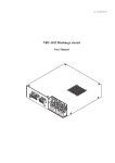
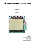
rev 1.02/ 2009 03 18
SBZ-2008 Simmer supply
User Manual
Overview / Applications
SBZ-2008 simmer supply is the device that strikes and maintains low-current
discharge in the flashlamp in order to increase lifetime and operation stability
of the lamp.
Input voltage – 24 VDC, max. output voltage – 200V, max. output current –
800mA, max. output power – 70W. Restrike rate is approximately 30 Hz.
SBZ-2008 may be used in laser systems with serial triggering as well as in
laser systems with external triggering.
Cooling
No external cooling is required.
Appearance
Connections, signals, signal descriptions
+24 VDC (TO +24V POWER SUPPLY MODULE): Molex 39-30-1040
PIN (color)
DESIGNATION
2 (red)
+24V DC
3 (blue)
+24V DC Return
DESCRIPTION
Connect to these pins positive wire of
24V DC power supply
Input: 17 ÷ 31V DC. Max. current 4A
Return from power supply producing 24V DC
OUTPUT (TO TRIGGERING TRANSFORMER AND LAMP):
Molex 39-30-1060
PIN (color)
DESIGNATION
DESCRIPTION
1, 6 (black)
OUTPUT Ground
Negative of triggering transformer primary winding
3 (blue)
OUTPUT Negative
Positive of triggering transformer primary winding
4 (red)
OUTPUT Positive
Flashlamp anode (+)
EXTERNAL TRIGGERING
SERIAL TRIGGERING
PIN 4
+
flashlamp
-
PIN 4
Triggering
transformer
Triggering
transformer
PIN 3
PIN 3
PIN 1,6
PIN 1,6
+
flashlamp
-
INTERFACE (SIMMER SUPPLY CONTROL): Molex 39-30-1040
PIN (color)
DESIGNATION
DESCRIPTION
1 (violet)
Sensor Return
Return Simmer Sensor signal
2 (yellow)
Simmer Sensor
Simmer Sensor circuit is closed while simmer current
flows through flashlamp and is open while simmer
current is absent
3 (red)
Enable
Since +5V DC voltage is applied to PIN3 simmer
supply tries to strike and maintain low-current discharge
(simmer) in the flashlamp.
If flashlamp triggering is failed simmer supply module
tries to trigger it again with approximately 30 Hz
repetition rate. After successful triggering the simmer
supply can support up to 800mA flashlamp current
(500mA is set by default).
Simmer will be maintained until 0V is applied to PIN3.
4 (black)
Enable Return
Return Simmer Enable signal
INTERFACE CIRCUITS:
INTERFACE:
Enable
INTERFACE:
Simmer Sensor
CURRENT REGULATION TRIMPOT
Simmer current is regulated by this trimpot (trimming potentiometer).
Value by default is about 500mA.
“ENABLE” JUMPER:
Use this jumper instead of ENABLE pin of INTERFACE.
Don’t use ENABLE pin and “ENABLE” JUMPER at the same time!
Safety
Warning! This equipment produces high voltages that can be very
dangerous. Don’t be careless around this equipment.
• Disconnect the module from the DC power source before making or
changing electrical or mechanical connections.
• SBZ-2008 simmer supply is designed to be installed inside a properly
grounded metal. It is the user’s responsibility to ensure that personnel
are prevented from accidentally contacting the SBZ-2008. Casual
contact could be fatal!
Operations
1. Connect +24V DC power supply, triggering transformer and
flashlamp to SBZ-2008 simmer supply
2. Disable simmer supply (PIN3 of INTERFACE)
3. Apply +24V DC power to the module
4. Enable simmer supply (set +5V DC on PIN3 of INTERFACE or
use “ENABLE” JUMPER)
5. Wait 5-10 seconds for Simmer Sensor. If it fails shut down your
system
To power down SBZ-2008
1. Remove +24V DC power from the module or DISABLE it.
Specification
+24VDC:
Voltage regulations
Maximal power consumption
SIMMER PARAMETERS
Output current
Output voltage
Max. output voltage
Max. output power
Open circuit voltage
TRIGGERING PARAMETERS
Voltage
Pulse width
Pulse energy
Restrike rate
Protections
Cooling
Environment:
Operation temperature
Storage temperature
Humidity
Size (LxWxH)
Weight
+24V +/– 7V DC
4A
300-800 mA (regulated)
depends on flashlamp type
200 V
70 W
up to 1350 V
1 kV
~1 us
~110 mJ
~30 Hz
Turn on with short circuit
No external cooling is required
-20 … +45 °C
-40 … +85 °C
90%, non-condensing
152x70x38 mm
0.2 kg