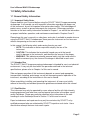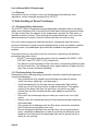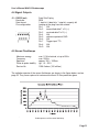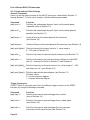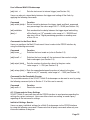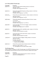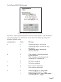
1
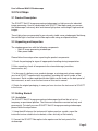
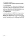
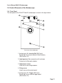
SCHOTT North America, Inc. Part number: A20960 Serial number:122 MaVi-S Image Processing Stroboscope User’s Manual and Technical Reference 122 Charlton Street, Southbridge, MA 01550-1960, USA Phone: 508-765-9744 Fax: 508-764-6273 www.us.schott.com/fiberoptics E-mail: [email protected] Congratulations on Your Purchase Thank you for purchasing the SCHOTT MaVi-S image processing stroboscope—a high-intensity light source for industrial image processing. Used with SCHOTT fiber optics and a camera, this instrument emits brief, intense light pulses that result in bright, clear, high-contrast images. Used by properly trained professionals, and maintained as detailed in this user’s manual, the SCHOTT MaVi-S image processing stroboscope will be a valuable addition to your facility. Please carefully observe the safety warnings described throughout this manual, as the SCHOTT MaVi-S image processing stroboscope is an extremely powerful light source. Proper precautions must be observed at all times during its operation. Product Warranty and Service The warranty for this SCHOTT instrument complies with the regulations described in SCHOTT’s General Terms and Conditions, as they exist at the time of your purchase. All product warranties are conditional on the instrument being used and maintained as described in this user’s manual. The product warranty does not apply to damage caused by incorrect usage, external forces or stresses, or failure to observe the operating instructions set forth in this manual. The warranty also is invalidated in the event that the equipment is tampered with, or modified without authorization. To return this instrument to SCHOTT, always use the original packaging. If the original packaging is not used, SCHOTT reserves the right to inspect the instrument for transportation or handling damage when it arrives at the SCHOTT facility. Please mark the package as fragile and sensitive to cold temperatures. When returning your stroboscope, please include a detailed written explanation of the reason for the return, as well as a comprehensive description of any performance problems you are experiencing. Trademarks Please be aware that all brand and product names mentioned in this user’s manual may be trademarks or registered trademarks of their respective companies or organizations. Product Identification Label MaVi-S Image Processing Stroboscope Page 2 User’s Manual MaVi-S Stroboscope Table of Contents 1.0 Safety Information . . . . . . . . . . . . . . . . . . . . . . . . . . . . . . . . . . . . . . . . . . . . . . . . . 5 1.1 General Safety Information . . . . . . . . . . . . . . . . . . . . . . . . . . . . . . . . . . . . . . . . . . . 5 1.1.1 Important Safety Notes . . . . . . . . . . . . . . . . . . . . . . . . . . . . . . . . . . . . . . . . . . 5 1.1.2 Intended Use . . . . . . . . . . . . . . . . . . . . . . . . . . . . . . . . . . . . . . . . . . . . . . . . . . 5 1.1.3 Qualification. . . . . . . . . . . . . . . . . . . . . . . . . . . . . . . . . . . . . . . . . . . . . . . . . . . 5 1.1.4 Disposal. . . . . . . . . . . . . . . . . . . . . . . . . . . . . . . . . . . . . . . . . . . . . . . . . . . . . . 6 1.2 Safe Handling of Xenon Flashlamps . . . . . . . . . . . . . . . . . . . . . . . . . . . . . . . . . . . . 6 1.2.1 Flashlamp Safety Information . . . . . . . . . . . . . . . . . . . . . . . . . . . . . . . . . . . . . 6 1.2.2 Flashlamp Safety Precautions. . . . . . . . . . . . . . . . . . . . . . . . . . . . . . . . . . . . . 6 1.3 Electrical Safety . . . . . . . . . . . . . . . . . . . . . . . . . . . . . . . . . . . . . . . . . . . . . . . . . . . . 7 1.3.1 Electrical Safety Information . . . . . . . . . . . . . . . . . . . . . . . . . . . . . . . . . . . . . . 7 1.3.2 Electrical Safety Precautions. . . . . . . . . . . . . . . . . . . . . . . . . . . . . . . . . . . . . . 7 1.3.3 Overload Protection. . . . . . . . . . . . . . . . . . . . . . . . . . . . . . . . . . . . . . . . . . . . . 8 2.0 First Steps . . . . . . . . . . . . . . . . . . . . . . . . . . . . . . . . . . . . . . . . . . . . . . . . . . . . . . . 9 2.1 Product Description. . . . . . . . . . . . . . . . . . . . . . . . . . . . . . . . . . . . . . . . . . . . . . . . . 9 2.2 Unpacking and Inspection. . . . . . . . . . . . . . . . . . . . . . . . . . . . . . . . . . . . . . . . . . . . 9 2.3 Getting Started . . . . . . . . . . . . . . . . . . . . . . . . . . . . . . . . . . . . . . . . . . . . . . . . . . . . 9 2.3.1 Installation . . . . . . . . . . . . . . . . . . . . . . . . . . . . . . . . . . . . . . . . . . . . . . . . . . . . 9 2.3.2 Main Power Connection . . . . . . . . . . . . . . . . . . . . . . . . . . . . . . . . . . . . . . . . 10 2.3.3 Opening the Instrument . . . . . . . . . . . . . . . . . . . . . . . . . . . . . . . . . . . . . . . . 10 2.4 Control Elements of the Stroboscope. . . . . . . . . . . . . . . . . . . . . . . . . . . . . . . . . . . 11 2.4.1 Front Panel . . . . . . . . . . . . . . . . . . . . . . . . . . . . . . . . . . . . . . . . . . . . . . . . . . 11 2.4.2 Back Panel . . . . . . . . . . . . . . . . . . . . . . . . . . . . . . . . . . . . . . . . . . . . . . . . . . 12 3.0 Operation . . . . . . . . . . . . . . . . . . . . . . . . . . . . . . . . . . . . . . . . . . . . . . . . . . . . . . . 14 3.1 Turning On and Off. . . . . . . . . . . . . . . . . . . . . . . . . . . . . . . . . . . . . . . . . . . . . . . . . 14 3.1.1 MaVi-S Stroboscope . . . . . . . . . . . . . . . . . . . . . . . . . . . . . . . . . . . . . . . . . . . 14 3.1.2 Xenon Flashlamp. . . . . . . . . . . . . . . . . . . . . . . . . . . . . . . . . . . . . . . . . . . . . . 14 3.2 Control Panel . . . . . . . . . . . . . . . . . . . . . . . . . . . . . . . . . . . . . . . . . . . . . . . . . . . . . 14 3.3 Functional Test . . . . . . . . . . . . . . . . . . . . . . . . . . . . . . . . . . . . . . . . . . . . . . . . . . . . 16 3.4 Locking the Control Panel . . . . . . . . . . . . . . . . . . . . . . . . . . . . . . . . . . . . . . . . . . . 17 3.5 Setting the Frequency Limit . . . . . . . . . . . . . . . . . . . . . . . . . . . . . . . . . . . . . . . . . . 17 3.6 Setting Single Flash Frequency . . . . . . . . . . . . . . . . . . . . . . . . . . . . . . . . . . . . . . . 18 3.7 Setting the Flash Intensity . . . . . . . . . . . . . . . . . . . . . . . . . . . . . . . . . . . . . . . . . . . 19 3.7.1 External Reference . . . . . . . . . . . . . . . . . . . . . . . . . . . . . . . . . . . . . . . . . . . . 19 3.7.2 Reference Diagram . . . . . . . . . . . . . . . . . . . . . . . . . . . . . . . . . . . . . . . . . . . . 19 3.7.3 Internal Reference . . . . . . . . . . . . . . . . . . . . . . . . . . . . . . . . . . . . . . . . . . . . . 20 3.8 Setting a Trigger. . . . . . . . . . . . . . . . . . . . . . . . . . . . . . . . . . . . . . . . . . . . . . . . . . . 20 3.8.1 External Triggers . . . . . . . . . . . . . . . . . . . . . . . . . . . . . . . . . . . . . . . . . . . . . . 20 3.8.2 Internal Trigger . . . . . . . . . . . . . . . . . . . . . . . . . . . . . . . . . . . . . . . . . . . . . . . 21 3.8.3 Trigger Delay . . . . . . . . . . . . . . . . . . . . . . . . . . . . . . . . . . . . . . . . . . . . . . . . . 21 Page 3 User’s Manual MaVi-S Stroboscope 3.9 Setting the Burst Function . . . . . . . . . . . . . . . . . . . . . . . . . . . . . . . . . . . . . . . . . . . 22 3.9.1 Burst Frequency . . . . . . . . . . . . . . . . . . . . . . . . . . . . . . . . . . . . . . . . . . . . . . 22 3.9.2 Number of Pulses . . . . . . . . . . . . . . . . . . . . . . . . . . . . . . . . . . . . . . . . . . . . . 22 3.9.3 Pulse Separation in the Burst . . . . . . . . . . . . . . . . . . . . . . . . . . . . . . . . . . . . 22 3.10 Reading and Resetting the Counter. . . . . . . . . . . . . . . . . . . . . . . . . . . . . . . . . . . 23 3.10.1 Total Counter . . . . . . . . . . . . . . . . . . . . . . . . . . . . . . . . . . . . . . . . . . . . . . . . 23 3.10.2 Resettable Counter . . . . . . . . . . . . . . . . . . . . . . . . . . . . . . . . . . . . . . . . . . . 23 3.11 Restoring the MaVi-S Default Settings. . . . . . . . . . . . . . . . . . . . . . . . . . . . . . . . . 24 3.12 Changing Fuses. . . . . . . . . . . . . . . . . . . . . . . . . . . . . . . . . . . . . . . . . . . . . . . . . . 25 3.13 Changing the MaVi-S Lamp . . . . . . . . . . . . . . . . . . . . . . . . . . . . . . . . . . . . . . . . . 25 3.14 Networking Several Stroboscopes (Master-Slave Function) . . . . . . . . . . . . . . . . 26 3.15 Power Adjustment of Several Stroboscopes . . . . . . . . . . . . . . . . . . . . . . . . . . . . 27 3.16 Instrument Cleaning. . . . . . . . . . . . . . . . . . . . . . . . . . . . . . . . . . . . . . . . . . . . . . . 28 4.0 Technical Specifications of MaVi-S . . . . . . . . . . . . . . . . . . . . . . . . . . . . . . . . . . 29 4.1 Standards Applied . . . . . . . . . . . . . . . . . . . . . . . . . . . . . . . . . . . . . . . . . . . . . . . . . 29 4.2 General Data . . . . . . . . . . . . . . . . . . . . . . . . . . . . . . . . . . . . . . . . . . . . . . . . . . . . . 29 4.2.1 Main Power Connection . . . . . . . . . . . . . . . . . . . . . . . . . . . . . . . . . . . . . . . . 29 4.2.2 Ambient Conditions . . . . . . . . . . . . . . . . . . . . . . . . . . . . . . . . . . . . . . . . . . . . 29 4.2.3 Housing . . . . . . . . . . . . . . . . . . . . . . . . . . . . . . . . . . . . . . . . . . . . . . . . . . . . . 29 4.2.4 Sound Emission. . . . . . . . . . . . . . . . . . . . . . . . . . . . . . . . . . . . . . . . . . . . . . . 29 4.3 Signal Inputs . . . . . . . . . . . . . . . . . . . . . . . . . . . . . . . . . . . . . . . . . . . . . . . . . . . . . 30 4.4 Signal Outputs . . . . . . . . . . . . . . . . . . . . . . . . . . . . . . . . . . . . . . . . . . . . . . . . . . . . 31 4.5 Xenon Flashlamps . . . . . . . . . . . . . . . . . . . . . . . . . . . . . . . . . . . . . . . . . . . . . . . . . 31 Appendix A: Operation of Interface RS232 . . . . . . . . . . . . . . . . . . . . . . . . . . . . . . . 33 A.1 Configuration of the Interface . . . . . . . . . . . . . . . . . . . . . . . . . . . . . . . . . . . . . . . . 33 A.2 Setting the Instrument Address . . . . . . . . . . . . . . . . . . . . . . . . . . . . . . . . . . . . . . . 33 A.3 Interface Commands . . . . . . . . . . . . . . . . . . . . . . . . . . . . . . . . . . . . . . . . . . . . . . . 33 A.3.1 Syntax of the Interface Commands. . . . . . . . . . . . . . . . . . . . . . . . . . . . . . . . 33 A.3.2 Commands to Define Settings . . . . . . . . . . . . . . . . . . . . . . . . . . . . . . . . . . . 34 A.3.3 Commands to Query Settings . . . . . . . . . . . . . . . . . . . . . . . . . . . . . . . . . . . . 35 A.3.4 Commands to Link to Other Systems . . . . . . . . . . . . . . . . . . . . . . . . . . . . . . 39 Appendix B: Declaration of Conformity. . . . . . . . . . . . . . . . . . . . . . . . . . . . . . . . . . 40 Page Index . . . . . . . . . . . . . . . . . . . . . . . . . . . . . . . . . . . . . . . . . . . . . . . . . . . . . . . . . 41 Page 4 User’s Manual MaVi-S Stroboscope 1.0 Safety Information 1.1 General Safety Information 1.1.1 Important Safety Notes Please read this user’s manual before using the SCHOTT MaVi-S image processing stroboscope. It will provide you with important information regarding the proper use of this instrument, as well as important information about safety. This knowledge will protect users, as well as prevent damage to the instrument. Please pay particular attention to the basic safety information included in Chapter 1, as well as the information on proper installation, operation, and maintenance contained in Chapters 2 and 3. Please keep this user’s manual in a safe place, and make it available to people who are using the SCHOTT MaVi-S stroboscope. Never pass the instrument on to a new user without also passing on the user’s manual. In this manual, the following safety and warning formats are used: • NOTE: This indicates an action required to simplify the use of the instrument. • CAUTION: This indicates that a potential hazard may exist that would result in damage to the instrument, and identifies the source of the danger. • WARNING: This indicates a potential personal safety risk that could result in death or serious injury; the source of the danger is identified in each case. 1.1.2 Intended Use The SCHOTT MaVi-S image processing stroboscope is intended for use in an industrial environment. It may only be used within the parameters defined in the technical specifications; please refer to Chapter 4 of this user’s manual. Safe and proper operation of this instrument depends on correct and appropriate transportation, handling, and storage, as well as the ongoing careful operation of the instrument, according to the instructions in this user’s manual. When assembling, installing, and operating the instrument, all users must strictly adhere to the safety and accident-prevention guidelines contained within this manual. 1.1.3 Qualification This instrument may only be operated by users who are familiar with high-intensity imaging equipment, and who have received special instruction in the proper use of xenon flashlamps. Please pay particular attention to the information on the safe handling of xenon flashlamps found in Section 1.2 of this user’s manual. Expert maintenance and repair work may only be carried out by SCHOTT, or by qualified personnel who are authorized by SCHOTT to perform such tasks. Users should never attempt their own instrument repairs. Page 5 User’s Manual MaVi-S Stroboscope 1.1.4 Disposal Instruments that are no longer in use must be disposed of according to local regulations, unless otherwise provided for by SCHOTT. 1.2 Safe Handling of Xenon Flashlamps 1.2.1 Flashlamp Safety Information The SCHOTT MaVi-S image processing stroboscope is equipped with an extremely stable xenon flashlamp that is focused into the fiber optics using an ellipsoid reflector. The light emitted from the aperture of the stroboscope, and from the fiber optics, is therefore extremely intense. When working with xenon flashlamps, users must take special precautions to ensure that this intense light does not enter the eye. Due to its extreme brightness and high frequency, stroboscopic light can lead to seizures or blackouts in people who are photosensitive or have an epileptic condition. For this reason, the stroboscopic light should be shielded to the greatest extent possible. To provide maximum user safety while the instrument is operating, the following precautions have been taken: • SCHOTT instruments generally comply with the standards EN 60825-1 (DIN VDE 0837) and CFR 1040.10 (US), respectively. • The aperture on the front panel of the instrument is covered by protective glass with an infrared filter. This safeguards users against splinters of glass that may result from a xenon flashlamp exploding. 1.2.2 Flashlamp Safety Precautions Please observe the following safety precautions related to xenon flashlamps when using the stroboscope: • Only qualified and fully trained users should be entrusted with setting up the instrument, adjusting it, and operating it. • Avoid looking directly into the high-intensity stroboscopic light with the naked eye, or with the aid of mirrors or optical instruments. This applies not only to the direct flash from the instrument, but also to any light emitted from the fiber bundles and fiber-optic adapters used with the instrument. • Only switch the stroboscope lamp on when you need to use it as a light source. • Always switch the stroboscope lamp off before positioning and configuring the stroboscope. • Only operate the stroboscope with the fiber optics connected, and shield the illuminated area completely from view. • Ensure that general lighting levels are high when you are working on an active, unshielded stroboscope, in order to minimize the difference in the brightness level between the stroboscopic light and the general facility in which you are working. Page 6 User’s Manual MaVi-S Stroboscope WARNING—Danger from high-intensity light: Do not use any reflective tools, wear a watch, or otherwise promote light reflection when you are working near the beam path of the lamp. WARNING—Danger from exploded splinters: The xenon flashlamps used in the MaVi-S stroboscope are under pressure and can explode. WARNING—Danger from electrical current: The instrument housing should never be opened by users; doing so risks personal injury. In the event that your xenon flashlamp needs to be changed, please contact your local SCHOTT representative to identify a SCHOTT repair house that can safely make this change. 1.3 Electrical Safety 1.3.1 Electrical Safety Information The SCHOTT MaVi-S image processing stroboscope complies with the electrical protection class 1 in accordance with the EU directive 73/23/EEC (low-voltage directive) and the protection rating IP40 (protection against solids > 1 mm, no protection against water). With correct power connection and appropriate use of the instrument for its intended purpose, user exposure to electrical current is prevented by its closed, grounded metal housing. This instrument complies with the EU directive 89/336/EEC (EMC directive) and is accordingly fail-safe (please refer to Section 4.1 and Appendix B of this user’s manual). 1.3.2 Electrical Safety Precautions Please observe the following electrical safety precautions when using this instrument: • The stroboscope may only be connected to AC systems of 50/60Hz with a nominal voltage in the range of 100V to 260V, using a three-pin main power cable with a grounded protective conductor. • Defective fuses may only be replaced by fuses of the same type, and with the same rating. For more information on fuse replacement, refer to the product information found on the back of the instrument, as well as Chapter 4 of this user’s manual. • The instrument must not be operated with an open housing; users should not open the housing. WARNING—Danger from electrical current: The instrument housing should never be opened by users. Expert maintenance and repair work—which includes changing xenon flashlamps—may only be carried out by SCHOTT, or by a qualified SCHOTT repair house. Please contact your local SCHOTT representative for more information. Page 7 User’s Manual MaVi-S Stroboscope 1.3.3 Overload Protection The energy for the stroboscope lamp is buffered in a capacitor block of 13µF/600V. In conjunction with certain frequency intensity combinations, this capacity can lead to impermissible power dissipation of the xenon flashlamp. A function of the processor, the Safety Area Control, prevents such impermissible parameter combinations. If values are entered which lead to impermissible power dissipation at the frequency limit set, then the instrument will not accept these values. The permissible value ranges are shown in the figures below. CAUTION—Danger from overloading: If you control the instrument externally via the BNC jack J4 – Intensity Ref, please note that the instrument’s overload protection feature is not active. In this case, you must strictly observe the frequency values shown below in order to protect against overload. Intensity I = f (Frequency) Intensity I = f (Burst Separation) Page 8 User’s Manual MaVi-S Stroboscope 2.0 First Steps 2.1 Product Description The SCHOTT MaVi-S image processing stroboscope is a light source for industrial image processing. Used in combination with SCHOTT fiber optics and your camera, the stroboscope’s extremely brief and intense light pulses create bright, high-contrast images. These light pulses are generated by an extremely stable xenon stroboscopic flashlamp; the emitted light is focused into the fiber optic cable using an ellipsoid reflector. 2.2 Unpacking and Inspection The stroboscope arrives with the following components: • MaVi-S image processing stroboscope • Main power cable Please follow these steps when unpacking the product components: 1. Check the packaging for signs of inappropriate handling during transportation. 2. After unpacking, check all components for external damage (scratches, loose screws, etc.). 3. In the case of a delivery error, product damage, or missing parts, please contact your local SCHOTT representative immediately, providing the serial number of the instrument. Serial numbers and identification labels can be found on the back panel of the instrument, as well as on the front cover of this user’s manual. 4. Retain the original packaging, in case you have to return the instrument to SCHOTT in the future. 2.3 Getting Started 2.3.1 Installation The SCHOTT MaVi-S image processing stroboscope should not be set up in a temporary or provisional position. The instrument should be mounted securely and permanently. To install your new SCHOTT MaVi-S image processing stroboscope, please follow the steps below. 1. Using the drill holes on the instrument’s bottom panel as a guide, mount the instrument onto a suitable level substrate, either vertically or horizontally. 2. Connect the SCHOTT fiber optics to the aperture on the front panel of the stroboscope. Page 9 User’s Manual MaVi-S Stroboscope 3. Connect the main power cable to the back of the stroboscope and to a grounded electrical socket. 2.3.2 Main Power Connection The main voltage input of the SCHOTT MaVi-S image processing stroboscope is set up as a wide range input connection, which can be connected to all main voltages with nominal values in the range of 100V to 260V. Defective fuses may only be replaced by fuses of the same type, and having the same rating. For more information on fuse replacement, refer to the product information found on the back of the instrument, as well as Chapters 3 and 4 of this user’s manual. Please note that both fuses are active, and both must be checked if there is a problem with fuse operation. 2.3.3 Opening the Instrument The stroboscope housing should only be opened to change the lamp. This is an expert task that can only be carried out by SCHOTT, or by qualified personnel who are authorized by SCHOTT to perform such tasks. Users should never open the stroboscope housing; doing so can cause personal injury and will invalidate the product warranty. WARNING—Danger from electrical current: The instrument housing should never be opened by users. Expert maintenance and repair work—which includes changing xenon flashlamps—may only be carried out by SCHOTT, or an authorized SCHOTT repair house. Please contact your local SCHOTT representative for more information. Page 10 User’s Manual MaVi-S Stroboscope 2.4 Control Elements of the Stroboscope 2.4.1 Front Panel The front panel of the SCHOTT MaVi-S stroboscope is shown in the figure below. 1 5 4 3 2 3 3 Front view of the stroboscope 1. Analog input J4 – Intensity Ref (BNC jack) Signal input for external control of flash intensity (See Section 4.3) 2. Light aperture (fiber connection with end stop) Connector for fiber-optic adapter 3. Adjustment screws Used only for servicing purposes 4. Fixing screw Used to secure the control panel 5. Analog input J3 – Trigger (BNC jack) Signal input for an external trigger signal (See Section 4.3) Page 11 User’s Manual MaVi-S Stroboscope 2.4.2 Back Panel The back panel of the MaVi-S image processing stroboscope is shown in the figure below. 1 9 2 8 3 WARNING ! Disconnect Main s before opening Mains: 100...240V AC; 0,6A; 50/60Hz Fuses : 2 x 1,6A / 250V TH 4 Manufactured by: GmbH D-76337 Waldbronn, Germany Model No.: BSV-II-Plus Serial No.: x xx xxxx Mfg.-Date: mm.yyyy I O 7 6 5 Rear view of the stroboscope 1. RS232 interface output J2 – RS232 (9-pin Sub-D plug) Interface output used to network several instruments (See Section 4.4) 2. General warning labels 3. Power connection warning labels Labels with technical information on fuses and main power connection 4. Product identification label This label includes the serial number of the instrument, as well as other information 5. Main power connection (socket for standard power cord) The main voltage input is a wide range input Page 12 User’s Manual MaVi-S Stroboscope 6. Fuse holders Use only main fuses 1.6A/slow-blow fuses, regardless of the main voltage. Both fuses are active, and both must be checked if there is a problem with fuse operation. Use extreme caution when replacing fuses. For more information on fuse replacement, refer to Chapters 3 and 4 of this user’s manual. WARNING!—Danger from electrical current: The instrument housing should never be opened by users. Expert maintenance and repair work—which includes changing xenon flashlamps—may only be carried out by SCHOTT, or by a qualified SCHOTT repair house. Please contact your local SCHOTT representative for more information. NOTE: Before checking the fuses, always ensure that the main power connection is turned off. 7. Main power switch This switch disconnects the stroboscope from its main power source (position O) and is used to turn off the instrument in case of danger. 8. Fixing screw for the control panel 9. RS232 interface input J1 – RS232 (9-pin Sub-D jack) Interface input used for communicating with a personal computer, or networking several instruments (See Section 4.3) Page 13 User’s Manual MaVi-S Stroboscope 3.0 Operation 3.1 Turning On and Off 3.1.1 MaVi-S Stroboscope The MaVi-S image-processing stroboscope is turned on via the main power switch on the back of the instrument (the “I” position). After it is switched on, the current firmware version briefly appears in the LED display. Then the operating status most recently used is automatically restored. The settings that were last selected are maintained, even if the instrument has been disconnected from electrical power for a long time. 3.1.2 Xenon Flashlamp The MaVi-S xenon flashlamp is controlled via the Strobe key. When the flashlamp is activated, the LED display will read “On.” When the lamp is turned off, the LED display will read “Off.” WARNING—Danger from high-intensity light: Avoid looking into the high-intensity MaVi-S light, or being exposed to it for long periods of time. Please refer to the safety information about working with xenon flashlamps found in Chapter 1 of this user’s manual. Input can be made via the control panel, whether the MaVi-S lamp is turned on or off, provided that the control panel has not been locked (please refer to Section 3.4). 3.2 Control Panel The control panel for the SCHOTT MaVi-S stroboscope is shown in the figure below. By pressing a key, you adjust the stroboscope performance characteristic—e.g., trigger source—that is controlled by this key. As you adjust various settings, the corresponding LED will light up, so you know which performance characteristic, or parameter, you are currently changing. Foil keyboard of the control panel 1. Strobe key This key is used to switch the stroboscope on and off (see Section 3.1, above). It has three positions: Page 14 User’s Manual MaVi-S Stroboscope On This indicates that the stroboscope lamp is switched on. This indicates that input is not possible, as the key lock has been activated (see Section 3.4). Keyboard locked Off This indicates that the stroboscope lamp is switched off. 2. Intensity Ref key This key is used to choose between internal and external control of the flash intensity. Internal External This indicates that flash intensity can be configured internally, via the control panel or the RS232 interface. This indicates that the flash intensity can be configured via an external signal through the BNC jack J4 – Intensity Ref. 3. Four-digit LED display The LED display shows the current four-digit value set for the parameter that is being controlled via the Select key. 4. Select key This key is used to select one of the four adjustable parameters of the stroboscope. The value that is currently set for the selected parameter is shown in the four-digit LED display. Intensity (%) Frequency (Hz) Burst Pulses (No.) Burst Pulse Separation (ms) This indicates the value of flash intensity, measured as a percentage. This indicates the frequency of the internal frequency generator, measured in hertz. This indicates the current number of pulses in a burst. This indicates the time delay between the individual pulses of a burst, measured in milliseconds (10 -3 seconds). 5. Adjustment keys +/– These keys are used to change the current settings to make the values higher (+) or lower (–). 6. Decimal Select key This key is used to select the position in the LED display that you want to change, by using the adjustment keys. The position that is currently selected flashes. Page 15 User’s Manual MaVi-S Stroboscope 7. Trigger key This key is used to select one of the four possible trigger sources: Pulse Video Slave Intern This indicates that the trigger pulse will come from input J3 – Trigger. This indicates that the trigger source will be a video signal at the input J3 – Trigger. This indicates that the trigger pulse will come from input J1 – RS232, connected to an upstream stroboscope. This indicates that the trigger source is an internally generated trigger signal. 8. Burst key This key is used to choose between an individual flash and the burst function. On This indicates that the burst function is switched on. Off This indicates that the burst function is switched off, and that the instrument is operating as a simple stroboscope. 9. Sensor key This key is not used, and its settings have no effect on operation. 3.3 Functional Test To carry out a first functional test on your new SCHOTT MaVi-S image processing stroboscope, please follow the steps below. 1. Turn on the stroboscope, using the main power switch on the back of the instrument (position I). 2. By repeatedly pressing the Trigger key, select the trigger source Intern. If this input is not accepted, and the message “Loc” appears in the LED display, then the control panel of the instrument is locked. In this case, switch the key lock to the “off” position, as described in Section 3.4. 3. By repeatedly pressing the Intensity Ref key, select the reference option Internal. 4. By repeatedly pressing the Strobe key, switch the stroboscope lamp on (LED adjacent to the strobe button will light). The stroboscope should now emit stroboscopic light. If the functional check was successful, you can now use the stroboscope as described in the following sections of this user’s manual. Page 16 User’s Manual MaVi-S Stroboscope If any errors occur during the functional check, contact your local SCHOTT representative for assistance. 3.4 Locking the Control Panel The MaVi-S stroboscope can be locked, in order to prevent unintentional changes to the settings. The button for locking the control panel is inside the pinhole opening at the side of the control panel. (See figure below.) Use a thin, non-metallic object to press the button inside the pinhole opening (labelled “1” in the figure above) located at the side of the control panel. When this button is 1 Side view of the MaVi-S stroboscope, showing the opening for locking the control panel pressed, the instrument is switched between two states: locked and unlocked. When the keys are locked via this button, the LED display on the control panel that is labelled “Keyboard locked” will light up. If any key is pressed on a locked control panel, the message “Loc” will appear in the LED display. Please note that it is still possible to control the instrument via the RS232 interface, even if the control panel is locked. See Appendix A for more information. 3.5 Setting the Frequency Limit Before configuring the stroboscope, select a frequency limit that reflects the highest expected frequency at which the instrument will be operating. The energy for the stroboscopic lamp is buffered in a capacitor block. The capacity of this block can be exceeded if the combined limits of frequency and intensity exceed the permissible operating range. The Safety Area Control function (see Section 1.3) uses the Page 17 User’s Manual MaVi-S Stroboscope frequency limit entered to calculate the range of acceptable values for both the intensity and the pulse frequency in a burst, and blocks the strobe from operating outside the acceptable range. To set the frequency limit, please follow these steps: 1. Press and hold the Select key. While holding it, press the + key repeatedly, until “FrLi” (for “frequency limit”) appears in the LED display. 2. Release the Select key and, using the Decimal Select key, choose the position in the LED display that you want to change. The selected decimal position in the LED display will flash. 3. Change the selected position by using the +/– keys. Once this is set, the Safety Area Control function will only allow values that are within the permissible power loss range for all subsequent settings. 4. To quit the menu, press the Select key and, while holding it, press the + key repeatedly, until “End” appears in the LED display. Release the Select key. Quitting the menu can also be accomplished by pressing both the Select key and the – key at the same time. The frequency limit is adjustable from 20Hz to 200Hz. The values allowed by the Safety Area Control function correspond to the following system: Minimum Value Description Maximum Value 8.0% 1Hz (1/FrLi)s Intensity (internal/external setting) Frequency Pulse separation (2000/FrLi) corresponds to 100% FrLi 250ms NOTE: Settings that fall outside the permissible power loss range are automatically overwritten by the Safety Area Control function. 3.6 Setting Single Flash Frequency The single flash frequency of the MaVi-S image processing stroboscope can be set from 1Hz to 200Hz. The step size is 0.1Hz. To change the single flash frequency, follow these steps: 1. Use the Select key to choose the LED “Frequency.” 2. Use the Decimal Select key to select the position in the LED display that you want to change. The selected decimal position in the LED display will flash. Page 18 User’s Manual MaVi-S Stroboscope 3. Change the value of the selected position using the +/– keys. If the desired value cannot be set, this means that it falls outside the permissible performance values of the xenon strobe lamp, and is blocked by the Safety Area Control function. More information on this can be found in Section 1.3 and Section 3.5 of this user’s manual. 3.7 Setting the Flash Intensity 3.7.1 External Reference The flash intensity can be controlled using an external power supply. To do so, follow these steps: 1. Press the Intensity Ref key to select “External.” The adjacent LED will illuminate. The instrument is now set to use the external intensity control. 2. Connect the external intensity reference signal to the BNC jack labelled J4 – Intensity Ref. The MaVi-S stroboscope converts the applied voltage to a flash intensity between 8.0% and 100%. The strobe flash intensity depends on the reference diagram selected (see Section 3.7.2, below). The intensity value is shown in the LED display. The following relationship limits apply: 0.6V = 8% 6V = 100% 3.7.2 Reference Diagram The relationship between the applied voltage and the resulting flash intensity is reflected in the reference diagram. You can choose between a linear reference diagram and a square one. The default setting for the MaVi-S instrument is the linear reference diagram. To change the reference diagram, follow these steps: 1. Press the Select key and, while holding it, press the + key repeatedly, until “rEF” appears in the LED display. 2. Use the + key to change to the setting “Lin” (for the linear reference diagram) or “Quad” (for the square reference diagram). 3. To exit the menu, press and hold the Select key. While holding the Select key, press the + key repeatedly, until “End” appears in the LED display. Release the Select key. You can also exit the menu by pressing both the Select key and the – key simultaneously. Page 19 User’s Manual MaVi-S Stroboscope The reference diagram has now been selected, and immediately becomes applicable to the external reference. 3.7.3 Internal Reference The flash intensity can also be controlled directly by the MaVi-S stroboscope, using the control panel. To do so, follow these steps: 1. Use the Intensity Ref key to select “Internal” mode. The adjacent LED will illuminate. The instrument is now set to the internal intensity control mode. 2. Use the Select key to choose the LED “Intensity.” The intensity value that is currently set will appear in the LED display. 3. Use the Decimal Select key to choose the position in the LED display that you want to change. The selected decimal position in the LED display will flash. 4. Change the selected position with the aid of the +/– keys. The intensity is adjustable from 8.0% to 100%. The step size is 0.1%. A change does not become effective until the first time the flash condenser is reloaded. This occurs following the second flash after the change has been made. If the desired value cannot be set, then it is outside the permissible range of values for the xenon lamp, and is blocked by the Safety Area Control function. More detailed information can be found in Section 1.3 and Section 3.5 of this user’s manual. NOTE: The charge level of the flash condenser is at a random level immediately after the MaVi-S stroboscope is switched on. Therefore, the first flash may be of a significantly higher intensity than the setting shown on the control panel. 3.8 Setting a Trigger There are four different ways to trigger the MaVi-S xenon flashlamp: external pulse, external video, external slave, or internal trigger. Every trigger impulse results in a flash. If the MaVi-S stroboscope is operating in burst mode (see Section 3.9), then every trigger impulse will set off a burst of flashes. 3.8.1 External Triggers To set one of the three external trigger options (pulse, video, or slave), follow these steps: 1. Use the Trigger key to select the external trigger source from these three options: Pulse Video Slave Page 20 Trigger using a pulse (rising edge) Trigger using a video signal Trigger using the signal of an upstream MaVi-S (see Section 3.14) User’s Manual MaVi-S Stroboscope 2. Connect the appropriate external trigger signal: Pulse Video Slave Impulse into the BNC jack J3 – Trigger Video signal into the BNC jack J3 – Trigger Trigger output signal of the upstream MaVi-S into the Sub-D jack J1 – RS232 (in) With a pulse trigger, the rising edge of the signal pulse is used. With a video trigger, the vertical trigger signal is filtered out of the video signal (please see Chapter 4). 3.8.2 Internal Trigger If required, the MaVi-S instrument can also generate a trigger signal internally, corresponding to the single flash frequency (see Section 3.6). To choose an internal trigger, use the Trigger key to select the “Internal” mode. The adjacent LED will illuminate. A trigger output signal is then also available via the BNC jack J2 – RS232 (out) to synchronize additional MaVi-S instruments operating in slave mode. The frequency of the trigger output signal corresponds to the flash frequency setting. 3.8.3 Trigger Delay Users can also set a time delay between the trigger signal and the stroboscopic flash. To create such a delay, simply follow these steps: 1. Press and hold the Select key. While holding it, press the + key repeatedly until “dELY” appears in the LED display. 2. Release the Select key, and then use the Decimal Select key to select the position in the LED display you want to change. The selected position in the LED display will flash. 3. Change the selected position, using the +/– keys. 4. To exit the menu, press and hold the Select key. While holding it, press the + key repeatedly, until “End” appears in the LED display. Release the Select key. You can also exit the menu immediately by pressing both the Select key and the – key simultaneously. The delay time between the trigger signal and the corresponding flash can be set between 0.01% and 99.99%. The step size is 0.01%, and a single step corresponds to 0.326µs. The following limits are given: Minimum delay time = 0.326µs (10-6 seconds) Maximum delay time = 3.254ms (10-3 seconds) Page 21 User’s Manual MaVi-S Stroboscope 3.9 Setting the Burst Function The MaVi-S image processing stroboscope also features a burst function. To switch on this feature, use the Burst key to select “Burst” mode. The adjacent LED will read “On.” The instrument has now been switched from single flash mode to burst mode. 3.9.1 Burst Frequency Users can customize the burst frequency of the MaVi-S stroboscope. To do so, follow these steps: 1. Use the Select key to choose “Frequency.” The adjacent LED will illuminate. In the LED display, the current setting for the frequency of bursts is displayed. 2. Use the Decimal Select key to select the position in the LED display that you want to change. The chosen position in the LED display flashes. 4. Change the selected position, with the aid of the +/– keys. If the desired value cannot be set, then it falls outside the permissible performance range of the xenon lamp, and is blocked by the Safety Area Control function. More detailed information can be found in Section 1.3 and Section 3.5 of this manual. 3.9.2 Number of Pulses The MaVi-S stroboscope also allows users to define the number of pulses for a burst. Simply follow these steps: 1. Use the Select key to choose the LED “Burst Pulses (No.).” The LED display will show the number of pulses currently set for a burst. 2. Use the Decimal Select key to choose the position in the LED display that you want to change. The selected position in the LED display will flash. 3. Change the value in the selected position with the +/– keys. The number of pulses can be adjusted from 1 to 250. 3.9.3 Pulse Separation in the Burst Users may also want to create a pulse separation when using the burst feature. This can be accomplished via the following steps: 1. Use the Select key to choose the LED “Burst Pulse Separation (ms).” The LED display shows the current separation between the pulses, in milliseconds (ms). Page 22 User’s Manual MaVi-S Stroboscope 2. Use the Decimal Select key to choose the position in the LED display that you want to change. The selected position in the LED display will flash. 3. Change the value in the selected position, using the +/– keys. NOTE: The overall time period of the pulse package—which includes the pulse separation and the number of pulses chosen—must be within the set frequency period for the burst. If the desired value cannot be set, then it is outside the permissible range of values for the xenon lamp, and is blocked by the Safety Area Control function. More detailed information can be found in Section 1.3 and Section 3.5 of this user’s manual. 3.10 Reading and Resetting the Counter 3.10.1 Total Counter The MaVi-S image processing stroboscope has two different counters for the flashes that have already been emitted. A static total counter records all of the flashes ever emitted by the instrument. This counter value is saved once per hour in the flash memory of the instrument. To read this counter, follow these steps: 1. Press and hold the Select key. While holding it, press the + key repeatedly, until “FLSU” appears in the LED display. 2. Release the Select key. The number of all flashes generated by the instrument so far is shown in the LED display. 3. To exit the menu, press and hold the Select key. While holding it, press the + key repeatedly, until “End” appears in the LED display. Release the Select key. You can also exit the menu quickly by pressing the Select key and the – key at the same time. The counter reading in the LED display is exponential, from 00E0 to 90E9 (90 x 109). This counter reading cannot be deleted. 3.10.2 Resettable Counter The resettable counter of the MaVi-S stroboscope records the number of flashes that have been emitted since the last reset. You can use this counter to estimate when the lamp will need to be changed. To read the counter, follow these steps: 1. Press and hold the Select key. Press the + key repeatedly, until “FLco” appears in the LED display. Page 23 User’s Manual MaVi-S Stroboscope 2. Release the Select key. The LED display will show the number of flashes since the last reset of the counter. 3. To exit the menu, press and hold the Select key. Press the + key repeatedly, until “End” appears in the LED display. Release the Select key. You can also exit the menu by pressing the Select key and the – key simultaneously. To reset this counter to zero, proceed as follows: 1. Press and hold the Select key. Press the + key repeatedly, until “FLco” appears in the LED display. 2. Release the Select key. The LED display shows the number of flashes since the last reset of the counter. 3. Press the – key. The counter is reset to zero. 4. To exit the menu, press and hold the Select key. Press the key repeatedly, until “End” appears in the LED display. Release the Select key. You can also press both the Select key and the – key at the same time in order to quickly exit the menu. The counter reading in the LED display is exponential, from 00E0 to 90E8 (90 x 108). 3.11 Restoring the MaVi-S Default Settings The MaVi-S can be returned to its default settings. These default settings are: Intensity Frequency Number of pulses per burst Separation between pulses in burst Burst Trigger Intensity reference Strobe 100% 1Hz 1 100ms Off Pulse External On To restore these default settings, follow these steps: 1. Press and hold the Select key. Press the + key repeatedly, until “rES” appears in the LED display. 2. Release the Select key. Page 24 User’s Manual MaVi-S Stroboscope 3. Keep the Strobe key pressed, and press the – key. The instrument is reset to its default settings. 4. To exit the menu, press and hold the Select key. Press the + key repeatedly, until “End” appears in the LED display. Release the Select key. To exit the menu immediately, you can simultaneously press the Select key and the – key. 3.12 Changing Fuses The holders for the fuses can be found on the back of the MaVi-S stroboscope (please refer to the figure on page 12). To check and change fuses, follow these steps: NOTE: Before checking and/or replacing fuses, always ensure that the main plug is disconnected. 1. Turn off the instrument, using the main power switch on the back, and unplug the main power connection. WARNING—Danger from electrical current: After switching the instrument off, wait for one minute to ensure that all the electric circuits of the MaVi-S stroboscope have discharged completely. It is possible that the MaVi-S may flash a few more times after being unplugged, because the capacitor must discharge completely. 2. Turn the fuse holder counter-clockwise, using a flat-bladed screwdriver. Remove the fuse holder and the fuse from the instrument. 3. If the fuse is defective, exchange it with a fuse of the same type and with the same rating. You will find technical information on replacement fuses on the MaVi-S warning label on the back panel of the instrument (see figure on page 12). You can also refer to Chapter 4 of this user’s manual. 4. Using the flat-bladed screwdriver, turn the fuse holder clockwise into the housing in order to replace it. NOTE: Both fuses are active, and both must be checked if there is a performance issue. 3.13 Changing the MaVi-S Lamp The xenon flashlamp of the MaVi-S image processing stroboscope needs to be changed at regular intervals. The xenon lamp has electrode material that is continuously vaporized by the arc and deposited on the inside of the lamp—causing the luminous efficiency over the life of the lamp to decrease. After approximately 10E8 flashes (100 million), the luminous efficiency falls to less than 70%, and the lamp should be changed. Page 25 User’s Manual MaVi-S Stroboscope Changing the xenon flashlamp requires opening the instrument housing, which could cause personal injury due to the high voltage associated with the flashlamp. Opening the instrument housing can also invalidate the MaVi-S product warranty. In the event that your lamp needs to be changed, please contact your local SCHOTT representative to identify a SCHOTT repair house that can safely make this change. WARNING—Danger from electrical current: The instrument housing should never be opened by users. Expert maintenance and repair work—which includes changing xenon flashlamps—may only be carried out by SCHOTT, or by qualified personnel who are authorized by SCHOTT to perform such tasks. WARNING—Danger from exploded splinters: The xenon flashlamps used in the MaVi-S stroboscope are under pressure and can explode. 3.14 Networking Several Stroboscopes (Master-Slave Function) The MaVi-S image processing stroboscope from SCHOTT enables users to network their instrument with several other MaVi-S instruments. In fact, each MaVi-S can be connected in a master-slave function with up to nine other stroboscopes. To establish this instrument network, follow these steps: 1. Working with the master MaVi-S stroboscope, define all the necessary settings on this instrument. 2. Connect the socket J2 – RS232 (out) of the master MaVi-S stroboscope to the jack J1 – RS232 (in) of the next MaVi-S instrument (RS232 cable, 1:1). 3. Connect the socket J2 – RS232 (out) of this second MaVi-S to the jack J1 – RS232 (in) of the next MaVi-S instrument. Repeat this step for each MaVi-S stroboscope in use. 4. For each of the slave stroboscopes connected to the master MaVi-S, use the Trigger key to select “Slave” mode. The adjacent LED will illuminate. 5. Adjust all other settings of the slave instruments to match those of the master MaVi-S, especially the trigger delay (refer to Section 3.8). The master-slave function only refers to the trigger signal. The first MaVi-S in the chain is the master MaVi-S, acting as the trigger source for the other MaVi-S instruments. All other settings have to be made individually for each MaVi-S stroboscope in the network. Page 26 User’s Manual MaVi-S Stroboscope 3.15 Power Adjustment of Several Stroboscopes For technical reasons, there are slight deviations in the xenon flashlamps and reflectors used in SCHOTT’s MaVi-S image processing stroboscopes. These deviations can lead to varying levels of brightness across MaVi-S stroboscopes, even if the instruments have the same intensity setting. To balance these intensity differences across multiple instruments, an intensity adjustment may be necessary for each MaVi-S stroboscope. A percentage value is set for the power adjustment, which determines the percentage of the power actually available to use for a flash, if the intensity on the instrument is set to 100%. To make a power adjustment on two MaVi-S instruments, follow these steps: 1. Select one MaVi-S stroboscope as the reference instrument, and set its intensity to 100% (refer to Section 3.7 of this manual). The MaVi-S with the weaker intensity should be used as the reference instrument. 2. Measure the intensity of this reference instrument, using a light meter or associated image analysis software. This value will be used as a benchmark for all other MaVi-S instruments used in conjunction with this reference stroboscope. 3. Set the intensity of the second MaVi-S instrument to 100%, and measure its intensity. 4. Estimate the percentage to which the intensity of the second MaVi-S stroboscope needs to be reduced, in order to attain the same intensity level as the reference instrument. 5. Press and hold the Select key. Press the + key repeatedly, until “PoAd” appears in the LED display. The value that was previously set will be shown in the LED display. 6. Use the Decimal Select key to choose the position in the LED display that needs to be changed. The selected position in the LED display will flash. 7. Change the selected position, using the +/– keys. 8. Now measure the intensity of the second MaVi-S stroboscope, using a light meter or associated image analysis software. Compare this value to the intensity of the reference instrument measured in Step 2. 9. Repeat steps 4 through 8 until the intensity of the second MaVi-S stroboscope corresponds to the intensity of the reference instrument. 10. To exit the menu, press and hold the Select key. Press the + key repeatedly, until “End” appears in the LED display. Release the Select key. Page 27 User’s Manual MaVi-S Stroboscope You can also quickly exit the menu by pressing the Select key and the – key simultaneously. 3.16 Instrument Cleaning The housing surfaces of the MaVi-S stroboscope can be cleaned using mild detergents or disinfectant solutions. Solvent-based cleaning products—including bleaches and acetone—should be avoided, along with abrasives. NOTE: Before cleaning the instrument, switch it off and unplug the main power connection. Page 28 User’s Manual MaVi-S Stroboscope 4.0 Technical Specifications of MaVi-S 4.1 Standards Applied Electrical safety IEC/EN 61010 (Safety requirements for electrical equipment for measurement, control, and laboratory use) EMC IEC/EN 61000 (EMC requirements on emission and immunity— electrical equipment for measurement, control, and laboratory use) Emission: FCC Class B IEC/EN 61000-6-3 Immunity: IEC/EN 61000-4-2 to 61000-4-6 and IEC/EN 61000-4-11 CSA-No. LR 221779 4.2 General Data 4.2.1 Main Power Connection Main voltage 100 – 260VAC Power consumption max. 75 VA Fuses 1.6A/slow-blow Protection class 1 (protective grounding) 4.2.2 Ambient Conditions Operating temperature Storage temperature Relative humidity Altitude of operating location 4.2.3 Housing Protection rating Instrument dimensions Base plate dimensions Weight 4.2.4 Sound Emission Sound level 32°F – 109.4°F (0°C – 43°C) -40°F – 194°F (-40°C – 90°C) max. 80%, non-condensing 0 – 9842.5 feet (0 – 3000 meters) above sea level IP40 4.33 in. x 7.87 in. x 7.28 in. (110 mm x 200 mm x 185 mm) 4.33 in. x 7.48 in. x .08 in. (110 mm x 190 mm x 2 mm) 4.41 pounds (2 kg) 61dBA at 1 meter distance Page 29 User’s Manual MaVi-S Stroboscope 4.3 Signal Inputs J1 – RS232 (in) Baud rate Data format Pin configuration 9-pin Sub-D jack 9600 1 start bit, 8 data bits, 1 stop bit, no parity bit Looking at the jack from the outside: Pin 1 N/A Pin 2 transmitted data T x D (→) Pin 3 received data R x D (←) Pin 4 N/A Pin 5 reference potential GND Pin 6 N/A Pin 7 Trigger input TTL Pin 8 N/A Pin 9 N/A J3 – Trigger (pulse/video) Voltage range Trigger level Input resistance Compatibility BNC jack 4 – 27V 2.2V 11.5kΩ TTL (5V) SPS (24V) PAL/CCIR video signal J4 – Intensity Ref Voltage range Setting range Input resistance BNC jack 0 – 6VDC 0.6V (≡ 8% intensity) – 6V (≡ 100% intensity) 40 kΩ CAUTION—Danger from overloading: If you control the instrument externally via the BNC jack J4 – Intensity Ref, please note that the instrument’s overload protection feature is not active. In this case, you must strictly observe the frequency values shown on page 8 of this manual, in order to protect against overload. Page 30 User’s Manual MaVi-S Stroboscope 4.4 Signal Outputs J2 – RS232 (out) Baud rate Data format Pin configuration 9-pin Sub-D plug 9600 1 start bit, 8 data bits, 1 stop bit, no parity bit Looking at the plug from the outside: Pin 1 N/A Pin 2 transmitted data T x D (→) Pin 3 received data R x D (←) Pin 4 N/A Pin 5 reference potential GND Pin 6 N/A Pin 7 Trigger input TTL Pin 8 N/A Pin 9 N/A 4.5 Xenon Flashlamps Maximum energy Frequency Spectrum Pulse-to-pulse stability Service life max. 2.16J electrical, at up to 20Hz max. 200Hz approx. 300 – 1000nm typ. 1.5 – 2.5% 10E8 flashes (100 million) The radiation spectra of the xenon flashlamps are shown in the figure below, and on page 32. They were captured in instruments without IR filter protection glass. Visible spectrum of the xenon flashlamp Page 31 User’s Manual MaVi-S Stroboscope IR Spectrum MaVi-S (without Filter) Relative Intensity 1400 1200 1000 800 600 400 200 IR spectrum of the xenon flashlamp Page 32 1096 1072 1049 1025 1000 976 951 927 902 877 852 827 801 776 751 725 700 0 User’s Manual MaVi-S Stroboscope Appendix A: Operation of Interface RS232 A.1 Configuration of the Interface As an alternative to operating the SCHOTT MaVi-S image processing stroboscope using the instrument’s control panel, all functions of the stroboscope can also be controlled via the RS232 interface. The RS232 interface has the following configuration: • 9600 Baud • 1 start bit, 8 data bits, 1 stop bit • No parity bit • No hardware or software handshake A.2 Setting the Instrument Address In order to control several stroboscopes via the RS232 interface, each instrument must first have a unique instrument address assigned to it. To set an instrument address, follow these steps: 1. Press the Select key and, while holding it, press the + key repeatedly, until “Adr x” appears in the LED display (“x” stands for the instrument address). 2. Now use the adjustment keys +/– to set the required instrument address. 3. To quit the menu, press the Select key and, while holding it, press the + key repeatedly, until “End” appears in the LED display. Release the Select key. Users can quit the menu immediately by pressing the Select key and the – key simultaneously. A.3 Interface Commands A.3.1 Syntax of the Interface Commands When describing interface commands in this appendix, the square brackets [ ] and the spaces are not part of the command. They are used here simply to clarify and improve the readability of the individual parts of each command. Each command must be confirmed with the Return key ( ). Before the actual command, you will find the address of the specific MaVi-S instrument that the command will be applied to. If several instruments are being operated together, then the corresponding instrument addresses have to be strung together. For example, the command “37setint80 ” sets the intensity for the instruments 3 and 7 to 80%. If no address is defined for the command, then the command will apply to all stroboscopes that are connected and networked at the time. Please note that all query commands allow only one instrument address to be given. Page 33 User’s Manual MaVi-S Stroboscope A.3.2 Commands to Define Settings General Commands Users can set the basic functions of the MaVi-S instrument—described in Section 3.1 through Section 3.7 of this user’s manual—with the following commands: Function Switches the stroboscope lamp on; input via the control panel is possible (refer to Section 3.1) Command [adr] stron Locks all keys on the control panel of the instrument (see Section 3.4) Unlocks all keys on the control panel of the instrument (see Section 3.4) [adr] setint [data] Sets the intensity to the given value in %; value range is 8 – 100 (refer to Section 3.7) [adr] refint Sets the instrument to internal intensity reference (see Section 3.7) Sets the instrument to an external intensity reference via the BNC jack J4 – Intensity Ref (refer to Section 3.7 and Chapter 4) [adr] keyopn [adr] keyloc Switches the stroboscope lamp off; input via the control panel is possible (see Section 3.1) [adr] stroff [adr] refext Sets the frequency to the given value in Hz; value range is 1 – 200 and step size is 0.1 (see Section 3.6) [adr] setref [data] Sets the required reference diagram (see Section 3.7) Possible values: 0 = Linear reference diagram 1 = Square reference diagram [adr] setfre [data] Trigger Commands SCHOTT MaVi-S users can select from four different trigger sources via the RS232 interface, by using the following commands: [adr] trivid Function Sets the instrument to external trigger from a pulse (refer to Section 3.8) Sets the instrument to external trigger from a video signal (see Section 3.8) [adr] trisla Command [adr] tripul Sets the instrument to external trigger from an upstream instrument via the slave function (see Section 3.8) Page 34 User’s Manual MaVi-S Stroboscope Sets the instrument to internal trigger (see Section 3.8) [adr] triint Users can also set a signal delay between the trigger and setting off the flash, by applying the following commands: Function Sets a time delay between the trigger signal and flash, expressed as a percentage; the value range is 0.01 – 99.99 (see Section 3.8) [adr] setdelabs [data] Sets an absolute time delay between the trigger signal and setting off the flash in ns (10-9 seconds); value range is 0 – 3000000 and step size is 54 ns. Digital processing generates a rounding error of max. 54 ns. Command [adr] setdel [data] Command [adr] buron [adr] buroff Commands for the Burst Mode Users can configure the MaVi-S instrument’s burst mode via the RS232 interface by using the following commands: Function Switches the burst mode on (refer to Section 3.9) Switches the burst mode off; the instrument then works in single flash mode again (see Section 3.9) [adr] setsep [data] Sets the number of pulses for a burst to the given value; value range is 1 – 250 (see Section 3.9) [adr] setpul [data] Sets the separation between the pulses of a burst to the given value in ms (10-3 seconds); value range is 1 – 1000 (see Section 3.9) Command for the Resettable Counter The resettable counter of the SCHOTT MaVi-S stroboscope can be reset to zero by using the following command (refer to Section 3.10 of this user’s manual): Command [adr] resflc Function Resets the counter A.3.3 Commands to Query Settings SCHOTT MaVi-S users can also use the RS232 interface to send queries regarding the settings for a given instrument. Users can either check one setting, or send a query regarding all the instrument’s settings. Individual Settings Queries Users can query individual settings for a MaVi-S stroboscope via the RS232 interface by using the following commands. Please note that all query commands allow only one instrument address to be given. Page 35 User’s Manual MaVi-S Stroboscope Function Queries the flash intensity setting; answer is in the form: [adr] telint: [data] Possible values range from 8 to 100% [adr] telfre Queries the single flash frequency setting; answer is in the form: [adr] telfre: [data] Possible values range from 1 to 200Hz Queries the separation between the pulses of a burst; answer is in the form: [adr] telsep: [data] Possible values range from 1 to 1000 ms Queries the delay time set for the trigger; answer is in the form: [adr] teldel: [data] Possible values range from 0.01 to 99.99 Queries the set number of pulses in a burst, answer is in the form: [adr] telpul: [data] Possible values range from 1 to 250 [adr] telpul Command [adr] telint [adr] telsep Queries the status of the resettable counter; answer is in the form: [adr] telflc: [data] Possible values are decimal numerals [adr] telfls Queries the status of the total counter; answer is in the form: [adr] telfls: [data] Possible values are decimal numerals Queries the reference diagram setting; answer is in the form: [adr] telref: [data] Possible values are: 0 = Linear reference diagram 1 = Square reference diagram [adr] telflc [adr] teldel Queries the current firmware version; answer is in the form: [adr] telver: [MaVi-S flash, fv = y.z] “y.z” corresponds to the firmware version number [adr] telref [adr] telver Total Settings Query Users can query all settings of a MaVi-S stroboscope via the RS232 interface by using the following command; please note that only one instrument address can be given: Function Queries the overall instrument status; answer is in the form: [adr] telsta: [abcdefghijklmn] Command [adr] telsta Page 36 User’s Manual MaVi-S Stroboscope Format for total settings queries via the RS232 interface The letters—which represent positions in the instrument’s answer—take on different values, depending on the instrument’s current status. The following is a key to the definitions of these values: Letter/position Value Meaning a 0 1 Stroboscope lamp is switched on. Stroboscope lamp is switched off; keys are locked. Stroboscope lamp is switched off; keys are released. 2 b 0 1 Flash intensity is controlled internally by the instrument. Flash intensity is controlled externally via the jack J4 – Intensity Ref. c 0 1 No function assigned. No function assigned. d 0 1 Burst mode is switched on. Burst mode is switched off. e 0 External trigger is set, using a pulse signal at the BNC jack J3 – Trigger. External trigger is set, using a video signal at the BNC jack J3 – Trigger. 1 Page 37 User’s Manual MaVi-S Stroboscope 2 3 f 0 1 2 3 External trigger is set, using a trigger signal from an upstream stroboscope through the jack J1 – RS232 (in). An internal trigger signal is set. In the field Select, the LED “Intensity” has been chosen. In the field Select, the LED “Frequency” has been chosen. In the field Select, the LED “Pulse” has been chosen. In the field Select, the LED “Separation” has been chosen. g x Value of the position 0 in the LED display (for the performance characteristic chosen in f) h x Value of the position 1 in the LED display (for the performance characteristic chosen in f) i x Value of the position 2 in the LED display (for the performance characteristic chosen in f) j x Value of the position 3 in the LED display (for the performance characteristic chosen in f) k 0 1 2 3 Value in the LED display has no decimal place. The decimal place in the LED is after position 1. The decimal place in the LED is after position 2. The decimal place in the LED is after position 3. l 0 1 Control panel is locked. Control panel is not locked. m 0 No position has been selected in the LED display. The position 0 has been selected in the LED display. The position 1 has been selected in the LED display. The position 2 has been selected in the LED display. The position 3 has been selected in the LED display. 1 2 3 4 n Page 38 No function assigned. User’s Manual MaVi-S Stroboscope Command [adr] key [1] [adr] key [2] [adr] key [3] [adr] key [4] [adr] key [5] [adr] key [6] [adr] key [7] [adr] key [8] [adr] key [9] A.3.4 Commands to Link to Other Systems The following set of commands will show MaVi-S users an exact replica of the current function of the keys on the instrument’s control panel. It serves as an excellent basis for generating a graphic user interface, or another link into existing control systems. As with other queries, please note that only one instrument address can be given. Function Corresponds to pressing the Strobe key once Corresponds to pressing the Intensity Ref key once Corresponds to pressing the Sensor key once Corresponds to pressing the Burst key once Corresponds to pressing the Trigger key once Corresponds to pressing the Select key once Corresponds to pressing the Decimal Select key once Corresponds to pressing the + key once Corresponds to pressing the – key once As an alternative to the command [adr] key [6] , the four possible settings of the Select key can also be chosen directly, by following this guide: Command [adr] selint [adr] selfre [adr] selpul [adr] selsep Function Selects the LED “Intensity,” measured as a percentage Selects the LED “Frequency,” measured in Hz Selects the LED “Burst Pulses,” expressed as a number Selects the LED “Burst Pulse Separation,” measured in ms Page 39 User’s Manual MaVi-S Stroboscope Appendix B: Declaration of Conformity Page 40 User’s Manual MaVi-S Stroboscope Page Index A Address, setting the instrument’s 33 Adjustment keys 15 Air humidity 29 Altitude 29 Ambient conditions 29 Assembly of stroboscope 9-10 B Back panel 12-13 Burst frequency, setting 22 Burst function, setting 22-23 Burst key 16 C Changing Flashlamp 25-26 Fuses 25 Cleaning housing surfaces 28 Climatic conditions 29 Commands for RS232 interface Burst mode 35 General 34 Linking to other systems 39 Queries 35-38 Resettable counter 35 Trigger 34-35 Configuration of RS232 interface 33 Conformity, Declaration of 40 Connector for fiber-optic adapter/fiber 11 Control elements Back panel 12-13 Front panel 11 Control panel Adjustment keys 15 Burst key 16 Decimal Select key 15 Intensity Ref key 15 LED display 15 Locking 17 Select key 15 Sensor key 16 Strobe key 14-15 Trigger key 16 Counters Resettable 23-24 Total 23 CSA, applied standards 29 D Damage to the instrument 2, 9 Decimal Select key 15 Declaration of Conformity 40 Default settings, restoring 24-25 Delay, trigger 21 Delivery errors 9 Description, product 9 Dimensions 29 Display, LED 15 Disposal of the instrument 6 E Electrical safety Safety information 7-8 Standards applied 29 EMC, applied standards 29 Emission, EMC standards 29 Error message in LED display (Loc) 17 EU directives, compliance with 40 External control Flash intensity 19-20 Trigger 20-21 Eye protection and warnings 6-7 F Fiber connector 11 Firmware version 14 Flash counters Resettable 23-24 Total 23 Flash frequency, setting 18-19 Flash intensity Controlling externally 19-20 Controlling internally 20 Flashlamp Replacing 25-26 Safety information 6-7 Technical specifications 31-32 Foil keyboard 14 Formats for warnings 5 Page 41 User’s Manual MaVi-S Stroboscope Frequency limit, setting 17-18 Frequency, setting Burst frequency 22 Limit for instrument 17-18 Single flash frequency 18-19 Front panel 11 Functional testing 16-17 Fuses Changing 25 Holders 13 Operating requirements 10 Technical specifications 29 G General safety 5-6 H Handling errors 9 Health warnings for users 6 Holders, fuse 13 Housing Cleaning 28 Safety warnings 7, 10, 13, 26 Specifications 29 I Identification label Image of 2 Inspection of 9 Position on the instrument 12 Immunity, EMC standards 29 Inspection when unpacking 9 Installation 9-10 Instrument Networking 26 Opening 10 Power adjustment 27-28 Unpacking 9 Instrument warning labels 12 Intended use 5 Intensity Controlling externally 19-20 Controlling internally 20 Intensity Ref jack 11, 30 Intensity Ref key 15 Page 42 Interface commands for RS232 Burst mode 35 General 34 Linking to other systems 39 Queries 35-38 Resettable counter 35 Trigger 34-35 J J1 – RS232 (in) jack, about 13 J1 – RS232 specifications 30 J2 – RS232 (out) plug, about 12 J2 – RS232 specifications 31 J3 – Trigger jack, about 11 J3 – Trigger specifications 30 J4 – Intensity Ref jack, about 11 J4 – Intensity Ref specifications 30 Jacks J1 – RS232 (in) 13, 30 J2 – RS232 (out) 12, 31 J3 – Trigger 11, 30 J4 – Intensity Ref 11, 30 K Keyboard 14-16 Keys Adjustment keys 15 Burst key 16 Decimal Select key 15 Intensity Ref key 15 Select key 15 Sensor key 16 Strobe key 14-15 Trigger key 16 L LED display 15 Light aperture 11 Loc error message 17 Locking the control panel 17 Long-term memory settings 14 User’s Manual MaVi-S Stroboscope M Main power connection Operating requirements 10 Position on the instrument 12 Specifications 29 Main power switch 13 Main voltage 29 Maintenance requirements 9-10, 28 Master-slave function 26 Mounting instrument 9-10 N Networking instruments 26 Number of pulses, setting (burst function) 22 O Opening the instrument 10 Operating requirements 10 Operating temperature 29 Overload protection 8 P Packaging 9 Plug, J2 – RS232 (out) 12, 31 Power adjustment 27-28 Power consumption 29 Precautions Electrical safety 7-8 Flashlamp safety 6-7 General safety 5-6 Health warnings for users 6 Product description 9 Product service 2 Product warranty, invalidating 2, 10 Protection class 7, 29 Protection rating 7, 29 Pulse interval, setting (burst function) 22-23 Pulse number, setting (burst function) 22 Q Qualifications for users 5 Queries via RS232 interface Individual settings 35-36 Total settings 36-38 R Radiation spectra of flashlamp 31-32 Reference diagram, flash intensity 19-20 Relative humidity 29 Replacing Flashlamp 25-26 Fuses 25 Resettable flash counter 23-24 Restoring default settings 24-25 Returning product 2, 9 RS232 (in) jack 13, 30 RS232 (out) plug 12, 31 S Safety Electrical safety 7-8 Flashlamp safety 6-7 General safety 5-6 Health warnings for users 6 Safety Area Control 8,17-20, 22-23 Saving settings 17 SCHOTT fiber connector 11 Select key 15 Sensor key 16 Separation between pulses, setting (burst function) 22-23 Servicing instrument 2 Setting Address for the instrument 33 Burst frequency 22 Burst function 22-23 Flash intensity, external 19-20 Flash intensity, internal 20 Frequency limit 17-18 Pulse separation (burst function) 22-23 Pulses, number of (burst function) 22 Single flash frequency 18-19 Trigger delay 21 Trigger, external 20-21 Trigger, internal 21 Signal inputs, specifications 30 Signal outputs, specifications 31 Single flash frequency, setting 18-19 Sound emission specifications 29 Page 43 User’s Manual MaVi-S Stroboscope Sound level 29 Spectra of flashlamp 31-32 Standards applied Declaration of Conformity 40 Technical specifications 29 Storage temperature 29 Strobe key 14-15 Stroboscopic lamp Switching off 14 Switching on 14 Syntax of RS232 interface commands Burst mode 35 General 34 Linking to other systems 39 Queries 35-38 Resettable counter 35 Trigger 34-35 T Technical specifications General data 29 Signal inputs 30 Signal outputs 31 Standards applied 29 Xenon flashlamps 31-32 Testing, functional 16-17 Total flash counter 23 Trademarks 2 Trigger Controlling externally 20-21 Setting internally 21 Trigger delay, setting 21 Trigger jack 11, 30 Trigger key 16 Page 44 U Unpacking the instrument 9 Use, intended 5 User qualifications 5 W Warning labels 12 Warnings, format for 5 Warranty, loss of 2, 10 Weight 29 Wide range input Main power connection 10 Operating requirements 10 X Xenon flashlamp Replacing 25-26 Safety information 6-7 Technical specifications 31-32 Fiber Optics SCHOTT North America, Inc. 122 Charlton Street Southbridge, MA 01550-1960 USA Copyright 2007. All Rights Reserved. PHONE: 508-765-9744 FAX: 508-764-6273 [email protected] Soy WEB: www.us.schott.com/fiberoptics