1
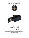
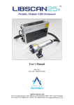
rev 1.10/ 2012 03 29
NBU-1012 Discharge circuit
User Manual
Overview / Applications
NBU-1012 discharge circuit is designed for simplification of solid-state laser
systems development. Module forms flashlamp pulses of quasi-rectangular
shape using the energy stored in external capacitors bank. Special feature of
the driver is built-in simmer module with complete triggering circuit for serial
or external flashlamp triggering.
NBU-1012 is intended for capacitor charging / pulse discharging applications
such as pulsed laser systems.
By default NBU-1012 is supplied in modification for serial triggering.
Modification for external triggering is available on request (see Part number
section).
Cooling
Module is cooled with embedded fan.
No external cooling is required.
Connections, signals, signal descriptions
CAPACITORS: M6 studs
C+ capacitor battery positive contact
C– capacitor battery negative contact
FLASHLAMP: M6 studs
LAMP+ positive flashlamp contact (anode)
LAMP– negative flashlamp contact (cathode)
CM (TO CAPACITOR CHARGING MODULE): Molex 39-30-1060
PIN (color)
DESIGNATION
DESCRIPTION
1, 2, 3 (red)
Positive CM
Positive contact connection from charging module
4, 5, 6
(black or blue)
Negative CM
Negative contact connection from charging module
+24 VDC (TO +24V POWER SUPPLY MODULE): Molex 39-30-1040
PIN (color)
DESIGNATION
DESCRIPTION
1, 2 (yellow)
+24V DC
Connect to these pins positive wire of 24V DC power
supply for correct operations of NBU-1012
Regulation: 17 ÷ 31V DC.
Maximum input current: 4A
3, 4 (green)
+24V DC Return
Return from power supply producing +24V DC
EXT (TO EXTERNAL TRIGGERING TRANSFORMER): Molex 39-30-1040
PIN (color)
DESIGNATION
DESCRIPTION
1, 2
Not Connected
3
Positive EXT
Positive of triggering transformer primary winding
4
Negative EXT
Negative of triggering transformer primary winding
This EXT connector is actual for NBU-1012-EXT (external triggering
modification) only. In standard NBU-1012 this connector may be absent or
non-functional.
PWF (PULSE CONTROL): Molex 39-30-1080
PIN (color)
DESIGNATION
DESCRIPTION
1 (black)
Interface Return
2, 4, 7
Not Connected
3 (orange)
Pulse
Duration of +5V DC pulse at PIN3 completely defines
IGBT-key open state time and, as consequence,
flashlamp pulse duration
5 (green)
Discharge
While 0V voltage is applied to PIN5 (or PIN5 is
unconnected), i.e. while Discharge is ON, capacitor
battery is continuously discharging on internal 1kOhm
50W resistor.
While Discharge is ON capacitor charging power
supply is blocked and capacitor charging is prohibited.
While +5V DC voltage is applied to PIN5 (Discharge is
OFF) module can be operated in the regular way.
6 (blue)
Monitor Return
Return Pulse and Discharge signals
–
Return Voltage Monitor signal
Voltage measured at PIN8 is a monitor signal
proportional to voltage on capacitor battery
8 (red)
Voltage Monitor
0V at PIN8 corresponds to 0V on capacitor battery;
10V at PIN8 corresponds to maximal voltage value
(1000V by default) on capacitor battery
PWF CIRCUITS:
PWF: Pulse
PWF: Discharge
1k
PWF: Voltage
Monitor
PIN 08
PIN 06
SIM (SIMMER SUPPLY CONTROL): Molex 39-30-1040
PIN (color)
DESIGNATION
1 (violet)
Sensor Return
Return Simmer Sensor signal
2 (yellow)
Simmer Sensor
Simmer Sensor circuit is closed while simmer current
flows through flashlamp and is open while simmer
current is absent
3 (red)
Enable
Since +5V DC voltage is applied to PIN3 embedded
simmer supply tries to strike and maintain low-current
discharge (simmer) in the flashlamp.
If flashlamp triggering is failed simmer supply module
tries to trigger it again with up to 30 Hz repetition rate.
After successful triggering the simmer supply can
support up to 800mA flashlamp current (500mA is
preset by default).
Simmer will be maintained until 0V is applied to PIN3.
4 (black)
Enable Return
SIM CIRCUITS:
SIM: Enable
SIM: Simmer Sensor
DESCRIPTION
Return Simmer Enable signal
Safety
Warning! This equipment produces high voltages that can be very
dangerous. Don’t be careless around this equipment.
• During operation the protective covers of the equipment must be
securely in place and all electrical connections must be properly
attached
• NBU-1012 discharge circuit is designed to be installed inside a
properly grounded metal. It is the user’s responsibility to ensure that
personnel are prevented from accidentally contacting the NBU-1012,
especially the CM Positive/Negative, C+/–, LAMP+/– connectors and
cable. Casual contact could be fatal!
• After shutdown, do not handle the capacitance load until it has been
discharged. Use an appropriate meter to check for complete discharge.
• Disconnect the module from the DC power source before making or
changing electrical or mechanical connections.
• Don’t remove protective covers! There are no user serviceable parts
inside this equipment.
Operations
1. Connect capacitor charging power supply, +24V DC power
supply, capacitor battery and flashlamp to NBU-1012 module
2. Set +5V DC voltage on PIN5 of PWF to switch off capacitor bank
discharging
Warning! By default capacitor discharging is on.
Be careful and always switch off capacitor discharging before
turning on your capacitor charging module.
Otherwise it may lead to capacitor charging module failure caused
with open-circuit operations
3. Disable simmer supply (PIN3 of SIM)
4. Apply +24V DC power to the module
5. Enable your capacitor charging power supply (charging module).
As soon as charging module starts operation, capacitors are charged
6. Enable simmer supply (set +5V DC on PIN3 of SIM)
7. Wait 5-10 seconds for Simmer Sensor. If it fails shut down your
system
8. Disable your capacitor charging power supply before pulse
Note that PCP and PCA-series power supplies are well-protected and
it isn’t obligatory to disable them. We recommend you to not disable
PCP (PCA) at high on-off time ratio
9. Set +5V DC pulse on PIN3 of PWF. This pulse duration defines
IGBT-key open state time and flashlamp pulse width.
10. Enable your power supply after pulse
11. Repeat #8-#10
To power down NBU-1012 and discharge capacitor battery
1. Turn off or Disable your capacitor charging power supply
(important!)
2. Disable simmer supply
3. Set 0V on PIN5 of PWF to switch on capacitor bank discharging.
Wait for complete discharge of capacitors.
Warning! Don’t use complete discharge of capacitor battery too
often because of discharging resistor overheating
4. Remove +24V DC power from the module.
Specification
+24VDC:
Voltage regulations
+24 V DC
Maximal power consumption
4 A (max)
PULSE PARAMETERS:
Max. voltage
1000 V
Max. discharge current (depends 1000 A for pulse width < 1 ms
on flashlamp impedance K0)
500 A for pulse width > 1 ms
Max. average power
3000 W
Min. pulse width
50 us (other on request)
Max. pulse width
10 ms (other on request)
Max. rep. rate
50 Hz (up to 200Hz on request)
RECOMMENDED WIRES:
For capacitor bank connections
LIFY 4 sq mm (min)
For flashlamp connections
LIFY 4 sq mm (min)
SIMMER PARAMETERS
Simmer current
500 mA (300-800 mA on request)
Max output voltage
200 V (300 V on request)
Max output power
70 W (100 on request)
Open circuit voltage
1500 V
FLASHLAMP TRIGGERING PARAMETERS
~ 10 kV negative pulse (NBU-1012)
Voltage
~ 1 kV negative pulse (NBU-1012-EXT)
Pulse width
~1 us
Restrike rate
1-30 Hz (automatically adjusted)
No external cooling is required
Cooling
Protections
From simultaneous capacitor battery charging and discharging
(see Discharge signal description)
From too short pulses (50us by default, other by request)
From too long pulses (10ms by default, other by request)
Environment:
Operation temperature
-20 … +45 °C
Storage temperature
-40 … +85 °C
Humidity
90%, non-condensing
210x203x58 mm
Size (LxWxH)
3.0 kg
Weight
DRAWINGS
Part number table
Part Number
NBU-1012
NBU-1012-EXT
Triggering
Serial
External
Example: NBU-1012-EXT
Options available on request:
• non-standard simmer current
• non-standard simmer voltage
• non-standard simmer power
• other minimal pulse width protection
• other maximal pulse width protection
• extended repetition rate range
System flowchart (Serial triggering modification)
System flowchart (External triggering modification)
NBU-1012-EXT module
LAMP +
Triggering
transformer
EXT +
+
+
-
flashlamp
+
EXT -
LAMP -
-
With external triggering modification NBU-1012-EXT we supply
triggering transformer as it shown at drawing. Of course you may use any
other construction of triggering transformer.