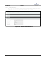
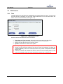
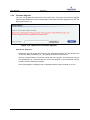
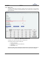
1
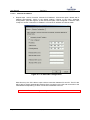
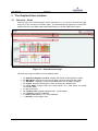
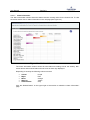
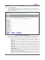
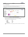
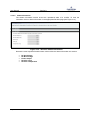
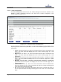
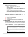
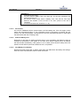
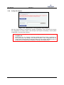
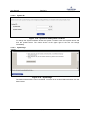
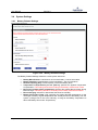
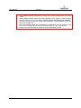
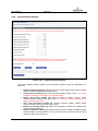
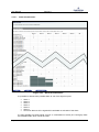
User Manual Version A FPRA IP20 Flexi Power Rectifier User Manual Version A . Page 1 of 53 10/25/2011 User Manual Version A Manual Number: 9702524-0000 Rev. A History: Date Version Author Change Notes 10/18/2011 10/25/2011 1.00 A Daniel Kreuzer Daniel Kreuzer Creation of document Released with version “A” Added Manual Number Authors: Daniel Kreuzer Abbreviations: tbd GUI MAC IP LCD CU PID VPN LVD to be done Web-based User Interface Media Access Control Internet Protocol Liquid Crystal Display Control Product Information Data Virtual Private Network Low Voltage Disconnect Related Documents: Installation Manual Page 2 of 53 10/25/2011 User Manual Version A Content 1 Overview ..................................................................................................................................... 5 2 Set up PC and connect to Web GUI ....................................................................................... 6 2.1 General ................................................................................................................................... 6 2.2 Set up the FPRA Control Unit ............................................................................................. 7 2.2.1 Change Control Unit IP-Address via GUI ........................................................................ 7 2.2.2 Change Control Unit IP-Address via LCD Display ........................................................... 7 2.3 Set up the User PC ............................................................................................................... 7 2.3.1 Connection to Control Unit via Intranet ......................................................................... 7 2.3.2 Direct Connection to Control Unit ................................................................................... 7 2.3.3 Set IP-address ................................................................................................................ 8 2.3.3.1 Allocate fixed IP-address ........................................................................................... 8 2.3.3.2 Alternate IP-address ............................................................................................... 11 3 2.4 Connect to the Graphical User Interface ....................................................................... 12 2.5 Change Browser Settings ................................................................................................. 12 The Graphical User Interface ................................................................................................ 13 3.1 Overview – Home ............................................................................................................... 13 3.2 Shelf ...................................................................................................................................... 15 3.2.1 CU ................................................................................................................................. 15 3.2.1.1 Alarm Information ................................................................................................... 16 3.2.1.2 Alarm Configuration ................................................................................................ 17 3.2.1.3 Product Information ................................................................................................ 19 3.2.1.4 Battery Information ................................................................................................. 20 3.2.1.5 Restart System ........................................................................................................ 21 3.2.2 Rectifier ........................................................................................................................ 22 3.2.2.1 Alarm Information ................................................................................................... 23 3.2.2.2 Status Information .................................................................................................. 24 3.2.2.3 Alarm Configuration ................................................................................................ 25 3.2.2.4 Product Information ................................................................................................ 27 3.3 Maintenance ........................................................................................................................ 28 3.3.1 Time.............................................................................................................................. 28 3.3.2 Firmware Upgrade ........................................................................................................ 29 3.3.3 Battery Test .................................................................................................................. 30 3.3.3.1 Set Battery Test Parameters ................................................................................... 31 3.3.3.2 Manually started test ............................................................................................... 31 3.3.3.3 Automatically started test (scheduled test) ............................................................ 31 3.3.3.4 AC-Fail test .............................................................................................................. 32 3.3.3.5 Alarm-In Battery Test.............................................................................................. 32 3.3.3.6 View Battery Test Results ....................................................................................... 32 3.3.4 Config. Ex-/Import ........................................................................................................ 33 3.3.5 System Notes & System ID & System logs................................................................... 34 3.3.5.1 System Notes .......................................................................................................... 34 3.3.5.2 System ID................................................................................................................ 35 3.3.5.3 Systemlogs .............................................................................................................. 35 3.4 System Settings .................................................................................................................. 36 3.4.1 Battery Related Settings ............................................................................................... 36 3.4.2 System Related Settings ............................................................................................... 38 Page 3 of 53 10/25/2011 User Manual Version A 3.4.3 Signal Out Settings ....................................................................................................... 40 3.4.3.1 Alarm Out Allocation ............................................................................................... 41 3.4.3.2 Alarm Active Setting ................................................................................................ 42 3.4.3.3 Alarm-In Setting ...................................................................................................... 42 3.4.3.4 Signal Out Test........................................................................................................ 43 3.4.4 Access ........................................................................................................................... 44 4 Front Panel LCD Display ......................................................................................................... 45 5 Table of Figures ....................................................................................................................... 46 6 Appendix A – Battery Charge/Discharge/Recharge Concept......................................... 47 7 Appendix B – Battery LVD Handling .................................................................................... 48 8 Appendix C – optional Load LVD Handling ......................................................................... 49 9 Appendix D – Front Panel Display Menu ............................................................................. 50 10 Appendix E – System Efficiency Increasing Functionality .............................................. 51 11 Appendix F – Typical System Set Up ................................................................................... 52 12 Appendix G – Minimum Recommended Hardware Requirements................................. 53 Page 4 of 53 10/25/2011 User Manual Version A 1 Overview This document is a “how to use” guide for the Web-based User Interface and for the LCD FrontPanel Display. The structure of this document follows the structure of the GUI, which means it is divided into main menus, sub menus and sections. Please consider the red-boxed Notes at any time. Please consider also Appendix C in section 9 for a typical system setup. Page 5 of 53 10/25/2011 User Manual Version A 2 Set up PC and connect to Web GUI 2.1 General This chapter describes how to set up the FPRA Control Unit and the User’s PC, and to be able to connect to the FPRA Control Unit via the Web-based Graphical User Interface. The web-based GUI is optimized for a resolution of 1024 x 768 pixels or higher. Both Microsoft Internet Explorer and Mozilla Firefox browsers are supported. Both are free of charge and actual version can be downloaded: Microsoft Internet Explorer: www.microsoft.com 1 Mozilla Firefox: www.mozilla.com 2 The Control Unit provides boundless connectivity within private intranets, which includes connections via VPN. It also supports direct connection between User PC and FPRA. Following the IEEE rules, each CU has its own unique MAC address. 1 2 Disclaimer: Links to Third-Party web sites or third party tools are provided for user convenience only. Emerson Network Power does not endorse nor support the content of third party links or tools. Emerson Network Power is not responsible for the content or the functionality of a third-party web sites or a third party tools. Privacy, security and quality policies may differ from those practiced by Emerson Network Power. Emerson Network Power does not represent any third party or third party tool. Page 6 of 53 10/25/2011 User Manual 2.2 Version A Set up the FPRA Control Unit In order to connect to the FPRA CU it may be necessary to change the IP-address of the CU. For connections through a private Intranet, it is required to allocate a unique IP-address to each Intranet-connected CU. This IP-address must be within the specified Intranet IP-Range. There are two different ways to change the IP-address of the FPRA CU. 2.2.1 Change Control Unit IP-Address via GUI To change the IP-address of the CU via the Web-based GUI it is necessary to connect with the “root-user” (see also section “Connect to the Graphical User Interface”). Under main menu “Maintenance” and within the submenu “Access” it is possible to change the IP-address. After updating the IP-address it is required to reconnect with the new IP-address. 2.2.2 Change Control Unit IP-Address via LCD Display Changing the IP-address via the LCD Display is most likely to be used during the first start-up, as it is not possible to connect to the CU. The CU will retain its default IP-address: • In order to change the IP-address on the LCD Display go to the main menu and select “Settings”. • In the IP-submenu hold the Enter Button (the middle one), until the question for activating DHCP appears o Choosing “yes” will activate the DHCP functionality and the CU will get an IP address from the network o Choosing “no” will lead to the next menu-step, where the IP-address can be changed manually Use the Up- and Down- Button to change the value of this digit. By holding the button the count-speed will increase. Use the Enter-Button to accept the value for the actual digit and jump to the next 8-bit digit. Using the Enter-Button after the fourth digits will lead to a new window, which asks to confirm or to cancel the update of the IPaddress. After confirming the update, the CU will restart. 2.3 2.3.1 Set up the User PC Connection to Control Unit via Intranet In order to connect to the Control Unit via Intranet there are no changes required. 2.3.2 Direct Connection to Control Unit In order to direct connect to the FPRA CU there are two possibilities how the User PC can be set up. Page 7 of 53 10/25/2011 User Manual 2.3.3 Version A Set IP-address There are two possibilities to set the systems IP-address: • • 2.3.3.1 Allocate fixed IP-address (see section 2.3.3.1) Alternate IP-address (see section 2.3.3.2) Allocate fixed IP-address 1. Go to the Network-Settings and to the “Properties” menu of the active TCP/IP connection (see also Figure 2.1). Figure 2-1 - Local Area Connection - Properties Page 8 of 53 10/25/2011 User Manual Version A 2. Choose the Internet Protocol (TCP/IP) menu and choose the “Properties” menu (see also Figure 2.2). Figure 2-2 - Internet Protocol (TCP/IP) – Properties Page 9 of 53 10/25/2011 User Manual Version A 3. Within the “General” menu choose the “Use the following IP address” option. The IP-address is bound to the IP-address of the CU and the “Subnet mask”. (e.g.: with the subnet mask “255.255.255.0” the first 3 digits of the IP-address of the User PC have to be same as the first 3 digits of the CU IP-address. The value of the last digit does not matter, but has to be a different to the last digit of the IP-address of the CU. See Figure 2.3. As an example, in this case the CU has the IP-address “192.168.100.100.” Figure 2-3 - allocate fix IP-Address With this set up the PC is able to open a direct connection between PC and CU. Building other connections will not be possible. To use the new settings click on OK. Then click on Close (or OK). For Windows 2000 3 , restart the PC for the new settings to take effect. For Windows XP 4 , the new settings are ready immediately, without re-starting 3 4 Disclaimer: Links to Third-Party web sites or third party tools are provided for user convenience only. Emerson Network Power does not endorse nor support the content of third party links or tools. Emerson Network Power is not responsible for the content or the functionality of a third-party web sites or a third party tools. Privacy, security and quality policies may differ from those practiced by Emerson Network Power. Emerson Network Power does not represent any third party or third party tool. Page 10 of 53 10/25/2011 User Manual 2.3.3.2 Version A Alternate IP-address 4. Repeat steps 1 and 2 of section “Allocate fix IP-address”. Choose the option “Obtain and IP address automatically” (which is the default setting). Change to the menu “Alternate Configuration” (see also Figure 2.4) and choose the option “User configured”. Follow the rules of step 3 in section “Allocate fix IP-address” to fill out the IP address and Subnet mask. Figure 2-4 - IP Alternate Configuration With this set up, the PC is able to open a direct connection between PC and CU. The PC also will be able to switch automatically between direct connection to the CU and connection to the Intranet/Internet depending on which connection is attached to the PC. • Page 11 of 53 Alternate IP-address settings are only available for Windows XP and later versions. 10/25/2011 User Manual 2.4 Version A Connect to the Graphical User Interface In order to connect to the FPRA System, open the Web-browser and type the IP-address of the CU in the address field of the browser. The GUI will ask for a “username” and “password”. Following User are supported: • • 2.5 Root User: Full Access to all functionality of the FPRA System o Username: “root” o Password: “default” Admin User: Reset Password of the Root User and the IP-address of the FPRA CU to its default values o Username: “resetpassword” o Password: “76z5g4v” Change Browser Settings In order to have the expected functionality, check the default location for downloaded data within your browser. This setting may get disturbed while using the configuration upload and download functions. To change the default download location use the browser help function. Page 12 of 53 10/25/2011 User Manual Version A 3 The Graphical User Interface 3.1 Overview – Home After user-login, the Overview page is shown (see Figure 3.1). To return to the Overview page at any time, click on Home in the Main Menu. The Overview (Home) page has no Sub Menu options and so the Sub Menu field remains blank until you choose a Main Menu option. Figure 3-1 - Home/Overview Page The Overview Page is divided into seven different areas: • • • • • • • • • • Page 13 of 53 A - System ID & System Location: displays the System ID and System Location B - Main Menu: used for the top-level navigation and drives the Sub Menu page C - Sub Menu: depending on the chosen Main Menu, the Sub Menu changes D - Logout: end the actual session in order to change to a different user E - Page Name: always shows the actual location, or in other words, the actual chosen Sub Menu F - CU: Control Unit G – Optional LVD: optional equipped LVD + Circuit Breaker H – Load CB: Load Circuit Breaker I – Battery LVD: Battery LVD + Circuit Breaker J - Rectifier: Power Supply Units 10/25/2011 User Manual Version A The Overview Page is an overview over the most important items and values of all elements of the system. The following indication colours are used: • • • • • Green: error free element Yellow: warning or a minor error Red: major or critical error Purple: Element Loss error Gray: Element not present/ not equipped • All indication colours depend on the Alarm Configuration settings of each element (see section 3.2.1.2 and section 3.2.3.3). The Element Loss fault is signalled by a purple colour at any time, regardless the Alarm Configuration settings. Element Loss only will be displayed if there was a previous communication between the elements. A faulty communication between elements at start up of the system will not be recognized as a fault, and the faulty element will be shown as not present. A absent temperature sensor will be displayed as “N/A”, if the correct setting in the “System Settings” is chosen • • • Page 14 of 53 10/25/2011 User Manual 3.2 Version A Shelf The following Shelf Sub Menus are available: • • • • 3.2.1 CU – Control Unit Rectifier 1 Rectifier 2 Rectifier 3 CU Figure 3-2 - CU Overview The Control Unit overview page gives access to more detailed information about the Control Unit. To access this detailed information, select Shelf from the Main Menu and select CU from the Sub Menu or just click on the SCU element in the Overview (Home) page. Sections: • • • • • Alarm Information Alarm Configuration Product Information Battery Information Restart System Click on the name of the sub section to expand it. Page 15 of 53 10/25/2011 User Manual 3.2.1.1 Version A Alarm Information The Alarm Information section shows the alarms that are currently active for the Control Unit. To view the active alarms click on Alarm Information in the unit page (see Figure 3.3). Figure 3-3 - CU Alarm Information The Alarm Information section shows all active alarms according to their set severity. Nonactive alarms and turned off alarms do not have an alarm sign displayed. Depending on severity the following colours are used: • • • • • Critical: Major: Minor: Warning: Indeterminate: Purple Red Orange Yellow Gray Click the “Reload Button” on the upper right of the section to reload the “Alarm Information” page. Page 16 of 53 10/25/2011 User Manual 3.2.1.2 Version A Alarm Configuration The Alarm Configuration section shows the severity-settings for the alarms available in the Control Unit. To view or change the severity of the alarms click on Alarm Configuration in “The Unit” page (see Figure 3.4). Figure 3-4 - CU Alarm Configuration Set the preferred severity of each alarm or restore all settings to their default value. The chosen severity the alarm is shown on the Overview page and on the Front Panel LEDS: • • • • • • Page 17 of 53 Critical: Shows the Alarm in the Alarm Information table as Critical. Activates the red LED on the front panel and displays the unit on the overview page with a red background Major: Shows the Alarm in the Alarm Information table as Major. Activates the red LED on the front panel and displays the unit on the overview page with a red background Minor: Shows the Alarm in the Alarm Information table as Minor. Activates the yellow LED on the front panel and displays the unit on the overview page with a yellow background Warning: Shows the Alarm in the Alarm Information table as Warning. Activates the yellow LED on the front panel and displays the unit on the overview page with a yellow background Indeterminate: Shows the Alarm in the Alarm Information table as Indeterminate. Does not activate any LED on the front panel and does not change the background color of the unit on the overview page. Off: Shows no Alarm in the Alarm Information table. Does not activate any LED on the front panel and does not change the background color of the unit on the overview page. 10/25/2011 User Manual Version A Buttons: • • • Update: stores the configuration to the system Undo: restores the settings to the last updated configuration Restore default: restores the default configuration. Click update to store the default configuration Example: Set the General Error Alarm to Critical or Major and the unit will be displayed with a red background on the overview page as long as General Error Alarm is active. Set it to Minor or Warning and the unit is displayed with a yellow background, while Indeterminate and Off do not change the units background color on the overview page (stays green). Page 18 of 53 10/25/2011 User Manual 3.2.1.3 Version A Product Information The Product Information section shows product-specific data for the Control Unit. To view the product data click on Product Information in the unit page (see Figure 3.5). Figure 3-5 - CU Product Information Review the CU PID-, Factory- and Connection-Data within the Production Information Section. Page 19 of 53 10/25/2011 User Manual 3.2.1.4 Version A Battery Information To view the Battery Information click on Battery Information in the Control Unit page (see Figure 3.6). Figure 3-6 - CU Battery Information The Battery Information section shows all relevant Battery Data. To change Manufacturer, ID and Capacity see also section 3.4.1. Page 20 of 53 10/25/2011 User Manual 3.2.1.5 Version A Restart System To restart the system click on Restart System in the Control Unit page then click on Restart in the expanded page when that opens (see Figure 3.7). Figure 3-7 - CU Restart System Click the restart button to perform a system restart. A restart of the system has following consequences: • Page 21 of 53 The system restarts with the initial charge state. No battery test is possible during the initial charge. 10/25/2011 User Manual 3.2.2 Version A Rectifier Figure 3-8 - Rectifier Overview Rectifier Sections: • • • • Alarm Information Status Information Alarm Configuration Product Information To view detailed information about a rectifier unit, click on the appropriate Section Heading for that Rectifier unit. Page 22 of 53 10/25/2011 User Manual 3.2.2.1 Version A Alarm Information The Alarm Information section shows the alarms that are currently active for the Rectifier. To view the active alarms click on Alarm Information in the Rectifier page (see Figure 3.9). Figure 3-9 - Rectifier Alarm Information The Alarm Information Sub Section shows all active alarms according to their set severity. Non-active alarms and turned off alarms do not have an alarm sign displayed. Depending on severity the following colours are used: • • • • • Critical: Major: Minor: Warning: Indeterminate: Purple Red Orange Yellow Gray Click the “Reload Button” on the upper right of the section to reload the “Alarm Information” page. Page 23 of 53 10/25/2011 User Manual 3.2.2.2 Version A Status Information The Status Information section shows the operational state of a rectifier. To view the information click on Status Information in the appropriate Rectifier page (see Figure 3.10). Figure 3-10 - Rectifier Status Information Review the most important Rectifier status values within the Status Information sub section: • • • • • Page 24 of 53 DC Set Voltage DC Bus Voltage Power Output Rectifier Load Rectifier Temperature 10/25/2011 User Manual 3.2.2.3 Version A Alarm Configuration The Alarm Configuration section shows the severity-settings for the alarms available in the Rectifier. To view or change the severity of the alarms click on Alarm Configuration in the Rectifier page (see Figure 3.11). Figure 3-11 - Rectifier Alarm Configuration Set the preferred severity of each alarm or restore all settings to their default value. Depending on the chosen severity the alarm is shown on the Overview page and on the Front Panel LEDS: • • • • • • Page 25 of 53 Critical: shows the Alarm in the Alarm Information table as Critical. Activates the red LED on the front panel and displays the unit on the overview page with a red background Major: shows the Alarm in the Alarm Information table as Major. Activates the red LED on the front panel and displays the unit on the overview page with a red background Minor: shows the Alarm in the Alarm Information table as Minor. Activates the yellow LED on the front panel and displays the unit on the overview page with a yellow background Warning: shows the Alarm in the Alarm Information table as Warning. Activates the yellow LED on the front panel and displays the unit on the overview page with a yellow background Indeterminate: shows the Alarm in the Alarm Information table as Indeterminate. Does not activate any LED on the front panel and does not change the background color of the unit on the overview page. Off: shows no Alarm in the Alarm Information table. Does not activate any LED on the front panel and does not change the background color of the unit on the overview page. 10/25/2011 User Manual Version A Buttons: • Update: stores the configuration to the system • Undo: restores the settings to the last updated configuration • Restore default: restores the default configuration. Click update to store the default configuration • Update all: stores the configuration for all Rectifiers to the system Example: Set the General Error Alarm to Critical or Major and the unit will be displayed with a red background on the overview page, as long as General Error Alarm is active. Set it to Minor or Warning and the unit is displayed with a yellow background, while Indeterminate and Off do not change the units background color on the overview page (stay green). Page 26 of 53 10/25/2011 User Manual 3.2.2.4 Version A Product Information The Product Information section shows product-specific data for the Rectifier. To view the product data click on Product Information in the Rectifier page (see Figure 3.12). Figure 3-12 - Rectifier Product Information Page 27 of 53 10/25/2011 User Manual 3.3 3.3.1 Version A Maintenance Time The date and time for the FPRA are maintained by an internal Real Time Clock. To view or set the date and time information for the FPRA select “Maintenance” from the Main Menu and select “Time” from the Sub Menu (see Figure 3.13). Figure 3-13 - Maintenance Time Set the local time and date within the Time Section: • • • • Enter Data and Time manually: follow the given format above the data fields Get PC-Time: copies the local time and date from the PC to the system Undo: recovers date and time to previous values Update: stores the new values to the system • • After updating the system with new values it is not possible to return to the old ones. Please note the data from the Real Timer Clock is used for the Battery Test Data and scheduled Battery Tests. An incorrectly set time may cause unexpected scheduled battery tests. The time is stored in an internal RTC device, which has its own battery back-up. Due to this it is possible to keep the actual time during a power loss or reset event. • Page 28 of 53 10/25/2011 User Manual 3.3.2 Version A Firmware Upgrade The user can upgrade the firmware for the Control Unit. To access the Firmware Upgrade feature select Maintenance from the Main Menu and select Firmware Upgrade from the Sub Menu (see Figure 3.14). Figure 3-14 - Maintenance Firmware Upgrade Upload new Firmware Browse the PC and choose the location of the authorized firmware file. The filename has to start with ENP_FPRAIP20_FW_” and will be provided in correct format. Click the “Upload” Button to send the chosen file to the system. The system will check if the uploaded file is a valid firmware file, then it will program it to the intended memory location and then restarts the systems. During the upgrade, a loading screen is displayed and the system restarts on its own. Page 29 of 53 10/25/2011 User Manual 3.3.3 Version A Battery Test To verify the health status of the battery, a battery test can be performed. To access settings or the results for the battery test select Maintenance from the Main Menu and Battery Test from the Sub Menu Figure 3-15 - Maintenance Battery Test The Battery Test checks the health status of a battery block. The following conditions will start a battery test: • • • • Manually started test Automatically started test (scheduled test) AC-Fail test Alarm-In Battery Test The goal of a battery test is to discharge a specified amount of Ampere Hours [Ahs] within a maximum duration [h], without reaching the warning or even the fail threshold Voltage [V]. Page 30 of 53 10/25/2011 User Manual 3.3.3.1 Version A Set Battery Test Parameters The battery test requires five different input parameters: • • • • • • Duration [h]: specifies the maximum duration of a battery test Ahs to Discharge [Ahs]: specifies the maximum Ampere Hours, which have to be discharged during a battery test Fail Threshold [V]: specifies the maximum battery voltage during a battery test. If reached the battery test will stop with a fail as result. A failing battery test also raises an alarm on the CU. The alarm will be active until restart of the system or a successful performed battery test. Warning Threshold [V]: specifies a threshold, which, if reached during the test, gives a warning as result. Reaching this threshold does not stop the battery test. Test Interval [d]: specifies the time between automatically performed battery tests. Each successful finished test will restart this interval, which means that even passed AC-Fail tests will restart the interval. Setting this parameter to zero will deactivate this functionality. Start Time [hh:mm]: specifies the start time for a periodic battery test. To update changed input parameters click the Update button. To update changed input parameters and start a battery test at once click the Start Battery-Test button. • • • • 3.3.3.2 Since each discharge lowers the life time of the batteries it is not recommended to perform more than one battery test per month. The smaller the load which has to be powered from the batteries the higher the “Fail Threshold” should be set. Deep discharges are extremely unhealthy for batteries. It is recommended not to discharge more than 80% of the total battery capacity. Manually started test To start a Battery Test manually on the GUI, click the Start Battery-Test Button. If the system is in a state which allows a battery test to be started, the test will start immediately. If the system is not in a state which allows a battery test to be started, the test will be queued and started as soon, as possible. 3.3.3.3 Automatically started test (scheduled test) If a Battery Test is required periodically, set the Interval to the preferred period. The Battery Test starts automatically when the amount of days since the last “passed” test has elapsed. Example 1: o Test Interval of 30 days o The last “passed” Battery Test is 29 days ago. So the next scheduled Test should be “tomorrow”. o An AC-Fail occurs, which starts a Battery Test. This AC-Fail Test finishes with the result “passed”. o The next scheduled test will be in 30 days, instead of 1 day Example 2: o Test Interval of 30 days o The last “passed” Battery Test is 30 days ago. So the next scheduled Test starts Page 31 of 53 10/25/2011 User Manual Version A Example 3: o Test Interval of 30 days o The last “passed” Battery Test is 29 days ago. So the next scheduled Test should be “tomorrow”. o An AC-Fail occurs, which starts a Battery Test. This AC-Fail Test stops because the duration of the AC-Fail is too short (result of the test is “stopped”). o The next scheduled test still will be in 1 day 3.3.3.4 AC-Fail test On each AC-Fail/Mains Fail the system starts a AC-Fail battery test. If the AC supply is back before the requested duration, or, the requested amount of discharge is reached, the test result is “AC-Fail Test Stopped”. Reaching one of the two parameters (duration or discharge) the test finishes with the according result. 3.3.3.5 Alarm-In Battery Test Depending on the Alarm-In Setting (see also section 3.4.3.3) a Battery Test starts on Alarm-In activation or deactivation. If the system is in a state, which allows a battery test to be started, the test will start immediately. If the system is not in a state, which allows a battery test to be started, the test will be queued and started as soon, as possible. 3.3.3.6 View Battery Test Results Review the results of the past 10 battery tests within the table below the battery test settings. Click the “Clear Test Records” button to clear all records. Page 32 of 53 10/25/2011 User Manual 3.3.4 Version A Config. Ex-/Import Figure 3-16 - Maintenance Configuration Import-Export Click the “Export” Button to download the System Configuration. Use the same file to import the configuration to another system. Use the export and import functionality to clone system configuration to several other systems. • • Page 33 of 53 For import of configuration only the following naming for the file is accepted: Config20*.bin. Read section 2.5 to change the browsers default download location. Depending on the used browser and settings, the download location of the configuration file can change. Before downloading configuration data check the default download location of the browser and change browser settings according to the requirements. 10/25/2011 User Manual 3.3.5 Version A System Notes & System ID & System logs To read or add notes, or to change the System ID and location, select Maintenance from the Main Menu and System Notes & System ID & Systemlogs from the Sub Menu. 3.3.5.1 System Notes Figure 3-17 - System Notes To add new notes enter your name and the notes you want to add. Click the Update button to save the notes. To download the note file right click on the disc symbol or the text below the notes and chose “Save Target As”. Page 34 of 53 10/25/2011 User Manual 3.3.5.2 Version A System ID Figure 3-18 - System ID and System Location To change the System ID/Name and/or the System Location enter the required names and click the update button. The names shown at the upper right of the GUI will change immediately. 3.3.5.3 Systemlogs Figure 3-19 - Systemlogs The latest Alarms/Actions can be reviewed. To see a list of archived Alarms/Actions click the button below. Page 35 of 53 10/25/2011 User Manual 3.4 3.4.1 Version A System Settings Battery Related Settings Figure 3-20 - Battery Related Settings The Battery Related Settings define the overall system behaviour: • • • • • • • Page 36 of 53 Battery Manufacturer: manufacturer of the used battery. Just for information. Battery Identifier: Identifier/Name of the used battery. Just for information. Nominal Capacity [Ah]: Overall Capacity of the used battery block Temperature Compensation per Cell [mV/°C]: specifies the applied Temperature Compensation. This setting should be according to the battery manufacturer’s data. Boost Cell Voltage Offset [x10mV/Cell]: specifies the applied Boost Voltage during Boost Charge. This setting should be according to the battery manufacturer’s data. Boost Charging: activates or deactivates the boost functionality Battery Disconnect Temp. [°C]: specifies the highest allowed temperature for the used type of battery. Higher temperatures will virtually disconnect the battery from the system. (Charge Limit is set to 5A internally, as long as the Battery Temperature is above the Battery Disconnect Temperature) 10/25/2011 User Manual • • • • • Page 37 of 53 Version A Set the Battery Related Parameters carefully to the values specified from the battery vendor. Set the Battery Related Parameters after installation of the system or after equipping the battery with a new type of batteries. Wrong settings may damage the batteries. Since not all types of batteries support boost voltage it is recommended to keep the Boost Cell Voltage at 0. Boost Cell Voltage Offset and Temperature Compensation per Cell values are per Cell. Lead acid battery blocks with an operating voltage of –48 V have 24 cells. Always check the Manufacturer's data for the specified battery values 10/25/2011 User Manual 3.4.2 Version A System Related Settings Figure 3-21 - System Related Settings The System Related Settings define the overall system behaviour (see also Appendix A on section 7): • • • • • • Page 38 of 53 Nominal Output Voltage [V]: defines the system target voltage without boost voltage offset and without temperature compensation. Charge Current Limit [A]: defines the maximum battery charge current. This setting should be according to the battery manufacturer’s data. Battery Disconnect Voltage [V]: defines maximum battery voltage before disconnecting the batteries from the system. This setting should be according to the battery manufacturer’s data. Opt. Load Disconnect Voltage [V]: defines maximum battery voltage before disconnecting the optional load from the system. Battery Low Voltage Alarm [V]: defines the threshold for battery low voltage alarm activation and deactivation. Battery Temperature Alarm [°C]: defines the threshold for battery temperature high alarm activation and deactivation. (As long as this alarm is active the charge limit is reduced to 50% of the set value.) 10/25/2011 User Manual • • • • • • • Page 39 of 53 Version A Initial Charge Time [h]: defines the duration of the initial charge. (See also Appendix A on section 7) Charge Time [h]: defines the charge duration after a battery discharge. (See also Appendix A on section 7) Boost Charge Time [h]: defines the duration after a battery boost discharge. (See also Appendix A on section 7) Temperature Sensor: defines if a temperature sensor is connected or not. The field have to be empty if no temperature sensor is connected. If no temperature sensor is connected, no temperature will be shown on the overview page. If no temperature sensor is connected the temperature disconnect and the temperature compensation are disabled. The smaller the load, which has to be powered from the batteries, the higher the “Battery Disconnect Voltage” should be set. Slow deep discharges are extremely unhealthy for batteries. The smaller the overall battery capacity, the smaller the Charge Current Limit should be set. It is recommend the set the Charge Current Limit not higher than 50% of the overall battery capacity (e.g.: 100Ahs battery capacity = max. Current Limit not above 50A) Always check the Manufacturer's data for the specified battery values 10/25/2011 User Manual 3.4.3 Version A Signal Out Settings Figure 3-22 - Signal Out Settings Signal Out Sections: • • • • Alarm Out Allocation Alarm Active Setting Alarm-In Setting Signal Out Test Click on the name of the sub section to expand it. Page 40 of 53 10/25/2011 User Manual 3.4.3.1 Version A Alarm Out Allocation Figure 3-23 - Alarm Out Allocation It is possible to allocate each possible alarm to one of the signal-out pins: • • • • • • • Alarm 1 Alarm 2 Alarm 3 Alarm 4 Alarm 5 Alarm 6 Off: set an alarm to off no signal will be activated on activation of the alarm It is also possible to activate signal out pins on combinations of active pins. Dark-grey fields are forbidden fields, which cannot be used. Page 41 of 53 10/25/2011 User Manual 3.4.3.2 Version A Alarm Active Setting Figure 3-24 - Alarm Active Settings Set the activation type to the preferred handling: • Active open • Active closed 3.4.3.3 Alarm-In Setting Figure 3-25 - Alarm In Settings Set the functionality of the Alarm-In pin: • Start battery test on alarm in activation • Start battery test on alarm in deactivation • ERPS Boost Charge • Turn this functionality off Page 42 of 53 10/25/2011 User Manual 3.4.3.4 Version A Signal Out Test Figure 3-26 - Signal Out Test To perform a Signal Out Test click the Start Test Button. All alarms on the signal pins will turn off for 10 seconds before turning on each alarm for 10 seconds. The Following order is used for turning on the signal pins: Time 0s – 10s 10s – 20s 20s – 30s 30s – 40s 40s – 50s 50s – 60s 60s – 70s Alarm 1 Off ON Off Off Off Off Off Alarm 2 Off Off ON Off Off Off Off Alarm 3 Off Off Off ON Off Off Off Alarm 4 Off Off Off Off ON Off Off Alarm 5 Off Off Off Off Off ON Off After the test is finished the signals will be set according settings and active alarms. • Page 43 of 53 During a Signal Out Test no alarms will be reported via the signal pins. 10/25/2011 Alarm 6 Off Off Off Off Off Off ON User Manual 3.4.4 Version A Access Figure 3-27 – Access For security and/or connection reasons, change the root password and/or the connection IP address. After updating the system will perform a restart. • Page 44 of 53 After changing the IP-address of the system, reconnect manually while using the new connection IP-address. 10/25/2011 User Manual Version A 4 Front Panel LCD Display The Front Panel LCD Display gives basic functionality for controlling and monitoring the system. It can; • • • • • Monitor all active alarms Monitor voltages and currents Monitor system PID data Monitor battery test results Monitor and change the connection IP address Since the LCD Display only supports basic functionality of the system this is not the main User Interface. For a detailed menu structure see also Appendix B on section 8). Page 45 of 53 10/25/2011 User Manual Version A 5 Table of Figures Figure Figure Figure Figure Figure Figure Figure Figure Figure Figure Figure Figure Figure Figure Figure Figure Figure Figure Figure Figure Figure Figure Figure Figure Figure Figure Figure Figure Figure Figure Figure 2.1 - Local Area Connection - Properties ...................................................................................... 8 2.2 - Internet Protocol (TCP/IP) – Properties ............................................................................... 9 2.3 - allocate fix IP-Address........................................................................................................ 10 2.4 - IP Alternate Configuration.................................................................................................. 11 3.1 - Home/Overview Page......................................................................................................... 13 3.2 - CU A Overview ................................................................................................................... 15 3.3 - CU A Alarm Information ..................................................................................................... 16 3.4 - CU A Alarm Configuration .................................................................................................. 17 3.5 - CU A Product Information .................................................................................................. 19 3.6 - CU A Battery Information ................................................................................................... 20 3.7 - CU A Restart System .......................................................................................................... 21 3.8 - Rectifier Overview .............................................................................................................. 22 3.9 - Rectifier Alarm Information ................................................................................................ 23 3.10 - Rectifier Status Information ............................................................................................. 24 3.11 - Rectifier Alarm Configuration ........................................................................................... 25 3.12 - Rectifier Product Information ........................................................................................... 27 3.13 - Maintenance Time ............................................................................................................ 28 3.14 - Maintenance Firmware Upgrade - Step 1 ........................................................................ 29 3.15 - Maintenance Firmware Upgrade – Step 3 .......................... Error! Bookmark not defined. 3.16 - Maintenance Battery Test ................................................................................................ 30 3.17 - Maintenance Configuration Import-Export ....................................................................... 33 3.18 - System Notes ................................................................................................................... 34 3.19 - System ID and System Location ...................................................................................... 35 3.20 - Battery Related Settings................................................................................................... 36 3.21 - System Related Settings .................................................................................................. 38 3.22 - Signal Out Settings........................................................................................................... 40 3.23 - Alarm Out Allocation ........................................................................................................ 41 3.24 - Alarm Active Settings ....................................................................................................... 42 3.25 - Alarm In Settings ............................................................................................................. 42 3.26 - Signal Out Test................................................................................................................. 43 3.27 – Access .............................................................................................................................. 44 Page 46 of 53 10/25/2011 User Manual Version A 6 Appendix A – Battery Charge/Discharge/Recharge Concept The Battery state machine mainly consists of five different parts: 1. 2. 3. 4. 5. 6. Initial Charge/Charge Start: after start-up the system is in initial charge state. This state guarantees fully charged batteries before changing to the default operational state. During this time it is not possible to start a battery test. The duration for the initial charge time is user settable and can be changed under “System Related Settings” – “Start Charge Time”. (see also section 3.4.2). It is not possible to stop the initial charge cycle in order to start a battery test, but it is possible to schedule a battery test, which starts directly after the initial charge. Charge Off/Idle State: this is the default operational state. This is the only state, which allows a battery test to be started. Battery Test: battery test is a simulated AC-Fail/Discharge State. After a battery test, the system will change to discharge state in order to recharge the batteries. Discharge State: Discharging more than 1% and less than 10% of total battery capacity will result in the Discharge State. If the AC/Mains returns before discharging more than 10% of total capacity of the batteries, the batteries will be recharged without boost voltage. The duration for the recharge is user settable and can be changed under “System Related Settings” – “Charge Time” (see also section3.4.2) Boost Discharge State: Discharging to more than 10% of total battery capacity will result in the Boost Discharge State. After AC/Mains returns, the batteries will be recharged with boost voltage. The duration for the boost recharge is user settable and can be changed under “System Related Settings” – “Boost Charge Time” (see also section 3.4.2) Manual Boost Charge State: A manually started Boost Charge can be performed during a normal charge or during Charge Off State. • Page 47 of 53 State changes from “Charging States” or “Charge Off State” requires a discharge of more than 1% of overall battery capacity. Depending on the overall battery capacity this may take several minutes. 10/25/2011 User Manual Version A 7 Appendix B – Battery LVD Handling Idle e rg ha us C tat S Discharge Floating Discharge State Open LVD >Disconnect Volt e t.T Ba mp Still AC Fail >Discon. Temp. e t.T Ba mp t ol t.V e Ba ag <Disconnect Volt >Discon. Temp. Still AC Fail r ie tif s ec tu R ta S <Discon. Temp. R r ie tif s ec atu St AC back & <Discon. Temp. Close LVD AC back Page 48 of 53 Idle 10/25/2011 User Manual Version A 8 Appendix C – optional Load LVD Handling Idle e rg ha us C tat S Discharge Floating Discharge State t ol t.V e Ba ag <Disconnect Volt Open LVD Still AC Fail >Disconnect Volt Still AC Fail r ie tif s ec tu R ta S R r ie tif s ec atu St AC back Close LVD AC back Page 49 of 53 Idle 10/25/2011 User Manual Version A 9 Appendix D – Front Panel Display Menu VIEW MODE ACT ALARM VOLTAGE TEMPERATURE ACT ALARM VOLTAGE VOLTAGE CURRENT CURRENT TEMPERAT TEMPERAT RETURN CURRENT VOLTAGE BATT.Temp. 0°C SYS.Curr 10.0A SYS.Voltage 46.88V ACTIVE ALARM R3InVoltLow CRITICAL R1 Temp. 10°C BATT.Curr 0.0A R1 Voltage 46.89V SysNomOvrTmp WARNING R2 Temp. 25°C R1 Curr 10.0A R2 Voltage 0.00V NO-WARNING R3 Temp. -5°C R2 Curr R3 Voltage 46.00V 0.0A R3 Curr 0.0A ROOT VIEW MODE BatTst REC VIEW MODE BatTst REC BATTERY TEST BatTst REC SETTINGS BatTstDate 10/05/2010 SETTINGS FPRA-INFO BatTstCurr 100.1A BatTstTime 120min BatTstVolt 45.08V WRITE MODE BAT CAP 25 Ah BAT CAP 25 Ah WRITE MODE BatChrgLim 25 A BAT-CHRG-LIM 25 A CONFIRMATION CONFIRMATION YES NO BatTstTemp 65°C BatTstDisc 120Ah CONFIRMATION CONFIRMATION YES NO BatTstStat RUNNING CONFIRMATION BAT-TEST START CONFIRMATION YES NO START or STOP or NIL IP WRITE MODE IP 10. 95. 144.185 IP 10. 95. 144.185 IP WRITE MODE IP 10. 95. 144.185 IP WRITE MODE IP 10. 95. 144.185 IP WRITE MODE IP 10. 95. 144.185 CONFIRMATION CONFIRMATION YES NO RETURN Restart System if „YES“ - Go back if „NO“ LEGEND FPRA-INFO Click the "acknowledged" button. PDA-Product Click the "up" button for YES, and the "down" button for NO. PDA SerNr. "Up" button symbol "Acknowledged" button symbol PDA-Rev. "Down" button symbol SW-Vers. 0.1 Page 50 of 53 Green Mareked Text: blinking on 123 Display. Use Up- and Down Button to change 10/25/2011 User Manual Version A 10 Appendix E – System Efficiency Increasing Functionality To increase the overall System efficiency rectifiers, which are not needed, are turned off. This functionality cannot be disabled and its behaviour cannot be changed. If any of the following alarms is active, this functionality is disabled (all Rectifier ON) at all: • Any Circuit Breaker Alarm • Any LVD Alarm • Rectifier Input Voltage Low • Rectifier General Error • Rectifier Power Limit • Rectifier Fan Error • Rectifier Exceptional Temperature • Rectifier Output Error During a Battery Test this functionality is disabled as well. The following thresholds are required to turn on/turn off additional Rectifier: 1. NO Rectifier is ON: a. All Rectifier will be set to ON 2. 1 Rectifier is ON: a. Turn ON a second Rectifier, if average output Power of the running Rectifier is above 85% 3. 2 Rectifier are ON: a. Turn ON a third Rectifier, if average output Power of the running Rectifier is above 85% b. Turn OFF a Rectifier, if average output Power of the running Rectifier is below 35% 4. 3 Rectifier are ON: a. Turn OFF a Rectifier, if average output Power of the running Rectifier is below 50% Page 51 of 53 10/25/2011 User Manual Version A 11 Appendix F – Typical System Set Up The following settings should give an idea of how to set up the system. These are not mandatory settings and should be considered a guide only as help, especially for inexperienced user. Please consider the Battery Manufacturer’s data at any time 500 (10A @ -50V) Battery Capacity [Ahs] 1500 (30A @ -50V) 3000 (60A @ -50V) 100 200 500 100 200 500 100 200 500 100 200 500 100 200 500 100 200 500 0 0 0 0 0 0 0 0 0 -53,5 -53,5 -53,5 Battery Related Parameters Nominal Capacity [Ah] 5 Boost Cell Voltage [x10mV/Cell] Temperature Compensation per Cell 3 [mV/°C] according Battery Manufacturer’s Data Min. Battery Temp [°C] according Battery Manufacturer’s Data Max. Battery Temp [°C] according Battery Manufacturer’s Data System Related Parameter Nominal Output Voltage [V] Charge Current Limit [A] 3 Battery Disconnect Voltage [V] Battery Low Voltage Alarm [V] 3 -53,5 -53,5 -53,5 -53,5 -53,5 -53,5 50 100 100 50 100 100 50 100 100 -43 -43 -43 -43 -43 -43 -43 -43 -43 -46,3 -46,3 -46,3 -46,3 -46,3 -46,3 -46,3 -46,3 -46,3 Initial Charge Time [h] 12 12 12 12 12 12 12 12 12 Charge Time [h] 4 6 8 6 8 10 8 10 12 Boost Charge Time [h] 3 5 7 5 7 9 7 9 11 Battery Test Settings Duration [h] 6 12 30 2 4 10 1 2 5 Ahs to Discharge [Ahs] 60 120 300 60 120 300 60 120 300 Fail Threshold [V] Warning Threshold [V] Test Interval [d] 34 5 -46,6 -46,6 -46,6 -46,4 -46,6 -46,6 -46,2 -46,4 -46,6 -47,5 50 -47,5 50 -47,5 50 -47,3 50 -47,5 50 -47,5 50 -47,1 50 -47,3 50 -47,5 50 Should also be according to the Battery Manufacturer’s Data. Page 52 of 53 10/25/2011 User Manual Version A 12 Appendix G – Minimum Recommended Hardware Requirements • • • • • • Page 53 of 53 Windows XP Operating System PC with 300 megahertz or higher processor clock speed recommended; Intel Pentium/Celeron family, or AMD K6/Athlon/Duron family, or compatible processor recommended 128 megabytes (MB) of RAM or higher recommended Ethernet 10/100 Base TX device or higher recommended Super VGA (800 x 600) or higher-resolution video adapter and monitor Keyboard and Mouse or compatible pointing device 10/25/2011

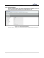
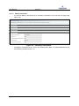
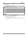
![Tester Bench [BETA] User Manual](http://vs1.manualzilla.com/store/data/005798606_1-651c3b6b51a13c0d6f27995a84bd9cc4-150x150.png)