1
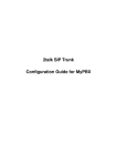
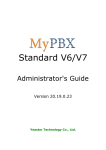
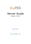
TB200/400 Installation Guide Version 1.0 Date: April 20th, 2015 Yeastar Information Technology Co. Ltd. TB200/400 Installation Guide Contents 0. Introduction......................................................................................................... 3 1. Preparation before Installation .......................................................................... 4 2. Hardware Specifications .................................................................................... 5 2.1 LED Indicators and Ports ................................................................................ 5 2.2 Specifications and Operating Environment...................................................... 6 3. TB200/400 Installation ........................................................................................ 7 3.1 Placement Instructions .................................................................................... 7 3.2 Installation Instructions.................................................................................... 7 3.2.1 Connection of Ethernet Ports .................................................................... 7 3.2.2 Connection of BRI Ports ........................................................................... 7 3.2.3 Power Connection .................................................................................... 8 3.2.4 Connection Diagram ................................................................................. 8 4. TB200/400 Basic Configurations ....................................................................... 9 4.1 Logging in the Web Configuration Panel ......................................................... 9 4.2 Network Settings ........................................................................................... 10 4.3 Make and Receive Calls ............................................................................... 10 4.4 Reset to Factory Defaults.............................................................................. 10 5. Conclusion ........................................................................................................ 11 2/11 TB200/400 Installation Guide 0. Introduction Yeastar TB200/400 is a compact and reliable standalone VoIP BRI gateway (BRI-VoIP/VoIP-BRI) offering 2 or 4 BRI ports for companies using ISDN BRI lines an easy, cost-effective and flexible integration into any VoIP system or enabling any IP PBX to be connected to the public ISDN network. This Guide explains how to install TB200/400 BRI VoIP Gateway, how to log in web interface, etc. 3/11 TB200/400 Installation Guide 1. Preparation before Installation Contents of the Box Upon receiving TB200/400 gift box, please open the package and check if all the items are supplied as TB200/400 Packing List (See Sheet 1). If there is any problem, please contact your provider. Note: please make sure the following devices are available before installation: Sheet 1 TB200/400 Packing List Item Unit QTY Description TB200/400 PC 1 Device unit Power cord PC 1 For the input of 220V AC power Network cable PC 1 Mounting ears PC 3 Long mounting ear: 1 PC; short mounting ear: 2 PCS M3 Screw PC 9 Warranty card PC 1 With Serial Number printed for Repair & Return 4/11 TB200/400 Installation Guide 2. Hardware Specifications 2.1 LED Indicators and Ports Front Panels Figure 2-1 TB200/400 Front Panels Table 2-1 Description of Front Panels No. Indication ① Reset button ② Power status ③ System status Status / Description Press the RESET button to restore the factory defaults. On The power is switched on. Off The power is switched off. Blinking The system is running properly. Not Blinking/Off The system goes wrong. LAN port is for the connection to Local Area ④ LAN port / ⑤ Console port / For Debugging. Blinking The BRI line is disconnected. On The BRI line is connected or in use. Off There is no BRI module inserted. / For the connection of ISDN BRI lines ⑥ ⑦ BRI port status BRI port Network (LAN). 5/11 TB200/400 Installation Guide Rear Panel Figure 2-2 TB200/400 Rear Panel Table 2-2 Description of Rear Panels No. Indication Description ① Power Switch Switch the device on or off. ② Power Inlet For connection of power supply. 2.2 Specifications and Operating Environment Table 2-3 TB200/400 Specifications and Operating Environment Items Description Size (L×W×H) 213 mm × 160 mm × 44 mm Power Supply 12V 1A Operating Temperature 0 to 40°C, 32 to 104°F Storage Temperature -20 to 65°C, 4 to 149°F Humidity 10%~90% (Non-condensing) 6/11 TB200/400 Installation Guide 3. TB200/400 Installation To avoid unexpected accident, personal injury or device damage, please read the following instructions before installing the Gateway. 3.1 Placement Instructions Ambient Temperature: to avoid overheating, please do not run TB200/400 in the place where the ambient temperature is above 104°F (40°C). Ventilation: please make sure that the device has good ventilation around. Anti-jamming: there may be some sources of interference that might affect the normal running of the Gateway. It’s highly recommended that the device Should be placed away from high-power radio, radar transmitters and high frequency, and high-current devices. Is using independent power junction box and effective anti-grid interference measures have been taken. Mechanical load: Please make sure that the device is placed steadily to avoid any accident that might cause damage. If placed on the desktop, please ensure it is horizontally placed. 3.2 Installation Instructions Place the Gateway in a suitable place, and then connect the power adapter and all other cables to complete the installation. 3.2.1 Connection of Ethernet Ports TB200/400 provides one 10/100M adaptive RJ45 Ethernet LAN port. LAN Port Connection Connect one end of a network cable to the LAN port of the Gateway, and the other end to any port of company’s LAN switch/router. If the LAN port is connected to PC directly (not via a switch), please use cross-over cable. 3.2.2 Connection of BRI Ports The BRI port could be connected to the BRI line and the BRI port of a traditional PBX with a BRI RJ45-RJ11 cable. 7/11 TB200/400 Installation Guide 3.2.3 Power Connection Connect the power adapter to the Gateway’s power port, and then plug the power adapter into an electrical outlet. Press the On switch to power on the Gateway. The gatewaywill start booting. In the meantime, users would see that the “POWER” and “RUN” indicator lights turn on. Please switch off the power before plugging or unplugging the cables. 3.2.4 Connection Diagram Figure 3-1 TB200/400 Connection Diagram (Front Panel) Figure 3-2 TB200/400 Connection Diagram (Rear Panel) 8/11 TB200/400 Installation Guide 4. TB200/400 Basic Configurations 4.1 Logging in the Web Configuration Panel TB200/400 provides web-based configuration interface for administrator. The user can manage the device by logging in the web interface. Check the factory defaults below: IP address: http://192.168.5.150 User Name: admin Default Password: password 1. Start the browser on PC. In the address bar, enter the IP address, click “Enter” button and then you can see the Web Configuration Panel login page (see Figure 4-1). 2. Enter the Admin User Name and Password to log in. Figure 4-1 TB200/400 Web Configuration Panel Login Page Via the configuration interface, the admin can make all the system configurations, including network settings (LAN, WAN, Firewall, VPN, DDNS, VLAN, etc.); system parameters configuration (time zone, password, etc.); internal settings (Web access port, etc.); BRI ports list; VoIP Trunks; Trunk Groups; Hotline; call logs (search, download); firmware update and reset, etc. After saving the changes, remember to click the “Apply changes” button to make the changes take effect. 9/11 TB200/400 Installation Guide 4.2 Network Settings After logging in the admin configuration interface, generally the first step is to configure the IP address. If the LAN ports are connected to the network, their IP addresses need to be configured. If not, just configuring the IP address of the LAN port which is connected to the local area network of the company is OK. LAN Settings Click “Network Preferences”-> “LAN Settings” on the left menu bar of the web configuration interface. LAN port is used for the interoperability of IP terminals and the device. If the LAN port is connected to the company’s LAN, please configure the correct IP address and corresponding subnet mask. Please note that after changing the IP address of LAN port, TB200/400 should be rebooted to make the new changes to take effect. 4.3 Make and Receive Calls 1. Calls from BRI to SIP Users should be able to receive BRI-to-SIP call after configuring a route on TB200/400 and an inbound route on SIP server if needed. Please refer to Yeastar TB BRI VoIP Gateways User Manual for details. 2. Calls from SIP to BRI Users should be able to make SIP-to-BRIcall after configuring a route on TB200/400 and an outbound route on SIP Server. Please refer to Yeastar TB BRI VoIP Gateways User Manual for details. 4.4 Reset to Factory Defaults To reset to factory defaults, you could follow the below instruction: Press the “RESET” button located in the back panel with a paper clip or a pencil tip. You can see the RUN indicator stops flicker and turns solid. When the RUN indicator turns off, the button could be released and system begins to reset. During the process, please do not power off until the RUN indicator become normal which means the reset process is completed. Note: after resetting, all the configurations made by the admin would be erased. 10/11 TB200/400 Installation Guide 5. Conclusion This Installation Guide only explains the installation and basic settings of TB200/400 BRI VoIP Gateways. For more functionality and advanced settings, please refer to the relative documents as below: “Yeastar TB BRI VoIP Gateways Datasheet” “Yeastar TB BRI VoIP Gateways User Manual” [The End] 11/11