1
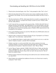
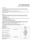
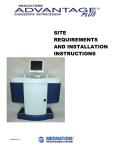
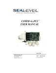
QUICK START GUIDE
TOTAL VIEW ONE M-Series
REVISION R1.07
PREMIUM NETWORK INTELLIGENCE
Copyright 2007/8. PresiNET Systems.
All rights reserved.
Table of Contents
Table of Contents .................................................................................................................. i Safety Instructions ............................................................................................................... 1 Warranty ............................................................................................................................ 1 Getting Technical Assistance .................................................................................................. 1 Rack Installation .................................................................................................................. 2 Unpacking ............................................................................................................................................................ 2 Rack Installation ................................................................................................................................................... 2 Port Specifications ................................................................................................................................................. 3 Setup Introduction ............................................................................................................... 3 Step 1 - Preparation – VERY IMPORTANT .............................................................................. 4 Step 2 – Default Configuration ............................................................................................... 4 Step 3 – Accessing TOTAL VIEW ONE ...................................................................................... 5 Step 4 - Activation ............................................................................................................... 5 Step 5 – Configure the System ............................................................................................... 6 Appliance Name Configuration ................................................................................................................................ 7 Mail Server IP / Hostname ...................................................................................................................................... 7 Network Configuration Table ................................................................................................................................... 7 Time Zone Configuration Table................................................................................................................................ 8 Monitored Network ................................................................................................................................................ 8 Step 6 - Connecting to your Network .................................................................................... 10 Specifications .................................................................................................................... 11 Liabilities and Disclaimer ..................................................................................................... 12 Activation Code .................................................................................................................. 13 Quick Start Guide M250, M500, M1000, and M2000
Page i
Safety Instructions
The following information relates to the safety of installation and maintenance personnel. Read all
instructions before attempting to unpack, install or operate this equipment, especially before
connecting the power adapter. Please keep the following in mind as you unpack and install this
equipment:
•
•
•
•
•
•
•
•
•
•
•
•
Always follow basic safety precautions to reduce the risk of fire, electrical shock and injury to persons.
Do not apply power before installation or when disconnecting this product from its original system setup.
To prevent fire or shock hazard, do not expose the unit to rain, moisture or install this product near
water.
Locate a safe and dry location to place this product. Keep it away from wet surfaces/surroundings.
Never push an object of any kind into this product through openings or empty slots, as you may
damage parts.
Do not attach the power supply cabling to building surfaces. Do not allow anything to rest on the power
cabling or allow it to be damaged by persons walking on it.
Distance your working area from moist floors, ungrounded power extension cables, and unavailable
safety grounds.
Avoid installation of this product during a lighting storm.
Damages caused by electrostatic discharge may result in total or intermittent system failures. To
minimize the possibility of ESD damage, an anti-static strap is highly recommended.
When cleaning or servicing this unit, avoid using highly toxic or aerosol cleaners. Use a clean damp cloth
when wiping its surfaces.
Do not place this device in a tight and sealed location. Place the unit where it can access sufficient
airflow to its vent holes (openings along its sides). Never block or cover these openings.
Do not disassemble this product on your own.
Warranty
TOTAL VIEW ONE Models M250, M500, and M1000 are provided with replacement hardware
warranty for one year from the date of receipt. Please visit www.PresiNET.com for warranty
terms and conditions.
Getting Technical Assistance
Should you encounter questions or problems with your TOTAL VIEW ONE Appliance, PresiNET
Systems is ready to assist you within the guidelines of our product support programs. First, check
the electronic product documentation for assistance. If you still cannot find the solution to your
problem, contact the PresiNET support team with the following information handy:
•
•
•
•
•
Model name
Part number
Local network configuration details
The abnormal behavior and/or error messages reported by your network system
Your questions, or a description of the problem you are experiencing
Call, fax, or e-mail PresiNET Systems for technical support.
Phone: 250-405-5368
Fax: 250-405-5362
E-mail: [email protected]
Note : You must register your TOTAL VIEW ONE Appliance with PresiNET to receive
technical support
Quick Start Guide M250, M500, and M1000
Page 1
Rack Installation
Unpacking
You should inspect the box the TOTAL VIEW ONE Appliance was shipped in and note if it was
damaged in any way. If the appliance itself shows damage, you should file a damage claim with the
carrier who delivered it.
Included with your TOTAL VIEW ONE Appliance should be:
•
•
•
•
•
One TOTAL VIEW ONE Appliance with mounting ears attached,
One 6 foot power supply
Two 6 foot network cables
Six screws (for mounting)
One 3 foot crossover cable.
If any of these are missing, please contact your vendor.
Rack Installation
The TOTAL VIEW ONE appliance comes with two rack mounting brackets, one on each side at the
front of the chassis. To mount the system into a rack, simply screw these brackets directly to the
front of the rack (two screws for each bracket). As the picture below shows, the brackets can be
located at the front of the chassis (left figure) or moved approximately one-third to the rear of the
chassis (right figure).
Installing TOTAL VIEW ONE into a Rack
•
Leave enough clearance in front of the rack to enable you to open the front door completely
(25 inches)
•
Leave approximately 30 inches of clearance in the back of the rack to allow for sufficient air
flow and ease in servicing.
Quick Start Guide M250, M500, and M1000
Page 2
•
This product is for installation only in a Restricted Access Location (dedicated equipment
rooms, service closets and the like).Equipment should be mounted into a rack so that the
amount of air flow required for safe operation is not compromised.
•
Equipment should be mounted into a rack so that a hazardous condition does not arise due
to uneven mechanical loading.
•
Consideration should be given to the connection of the equipment to the power supply
circuitry and the effect that any possible overloading of circuits might have on over current
protection and power supply wiring. Appropriate consideration of equipment nameplate
ratings should be used when addressing this concern.
•
Basic electrical safety precautions should be followed to protect yourself from harm and the
TOTAL VIEW ONE server from damage
•
Be aware of the locations of the power on/off switch on the chassis as well as the room’s
emergency power-off switch, disconnection switch or electrical outlet. If an electrical
accident occurs, you can then quickly remove power from the system.
•
The power supply power cords must include a grounding plug and must be plugged into
grounded electrical outlets.
When you are finished, connect the power supply to the rear of the appliance, and plug it into your
power source.
You have completed installation of your TOTAL VIEW ONE Appliance. Please refer to the TOTAL VIEW
ONE Setup manual for instructions on how to connect your Appliance to a switch in your network.
Port Specifications
TOTAL VIEW ONE (M250, M500, M1000 and M2000) have
the following interface specification:
(1)
(2)
(3)
(4)
– Power Outlet,
– USB Interfaces
– Management Port and
– Sensor Port
Setup Introduction
The Quick Start Guide gives you the information you need to execute the most common
implementation for TOTAL VIEW ONE. For other implementation options, please read the
“monitoring theory” section in the User Manual.
The Quick Start Guide will show you how to:
•
•
Connect to the TOTAL VIEW ONE Appliance;
Configure the TOTAL VIEW ONE Appliance so that it will monitor the internet link going to
your firewall (as an example).
Quick Start Guide M250, M500, and M1000
Page 3
Step 1 - Preparation – VERY IMPORTANT
You will need to complete the following preparation tasks to successfully install your TOTAL VIEW
ONE Appliance:
1) Do you have a managed switch that supports port replication / port mirroring?
a. Identify the link on the switch you wish to monitor and replicate a port on the switch
at that link. For example, you can monitoring the Internet Link going to your firewall,
so you will replicate a port on that switch (please refer to your switch manual on port
replication or port spanning or port mirroring).
NOTE: Only managed Switches or Routers have the ability to do port
replication. Please ensure that the switch has port replication capability.
b. If you don’t have a managed switch that supports port replication, you may use a HUB
or a network Ethernet TAP.
2) You will also need the following information to configure your TOTAL VIEW ONE Appliance:
a. Identify the VLANS that are on your switch;
b. The IP address and subnet mask on your network you wish to assign to the sensor for
web access;
c. The gateway IP of your router to allow access to the internet for updates;
d. The subnets (Monitored Networks) you wish the TOTAL VIEW ONE Appliance to
monitor;
e. The IP addresses of any DNS , mail, and NTP servers you wish to use with your TOTAL
VIEW ONE Appliance; and
f.
Your time zone.
Step 2 – Default Configuration
TOTAL VIEW ONE ships with a default configuration in order to access the setup menu and
configure the appliance for your network.
Default IP Address
Default SUBNET MASK
Default Gateway
Default SENSOR ACCOUNT
Administrator account
Administrator password
=
=
=
=
=
=
Quick Start Guide M250, M500, and M1000
192.168.1.1
255.255.255.0
192.168.1.254
TOTAL VIEW ONE
Admin (Note: Case sensitive)
password (Note: Case sensitive)
Page 4
Step 3 – Accessing TOTAL VIEW ONE
To configure the TOTAL VIEW ONE appliance, you will need to access the device using the Default
Configuration Information above.
1. Turn on the TOTAL VIEW ONE Appliance;
2. Connect directly to the Appliance using the crossover cable provided, from a laptop or
workstation outside of the network, to “Port 1” on the Sensor, using the crossover cable
provided;
3. Open a web browser;
4. Access the TOTAL VIEW ONE Appliance by entering the Default IP address (192.168.1.1)
into your browser;
5. A TOTAL VIEW ONE login page will appear. Use the username “Admin” (case sensitive), and
the default password “password” to login as administrator.
Step 4 - Activation
TOTAL VIEW ONE will now ask that you activate your appliance. Enter the key code printed
on the last page of this manual in the field provided, then click on the “Activate” button.
Quick Start Guide M250, M500, and M1000
Page 5
Step 5 – Configure the System
Now that you have successfully activated your TOTAL VIEW ONE Appliance, you will be taken
to the “Setup” page, where you will edit the default configuration
1) Edit the configuration information by pressing the “Edit” button in the various sections.
Quick Start Guide M250, M500, and M1000
Page 6
Appliance Name Configuration
The Appliance name is the name you set, and will be displayed in the client pull down menu.
To edit the Client name, press the “Edit” button, enter the new name and the appliance
location, and press “Submit”.
Mail Server IP / Hostname
This is where you will set the Mail Server IP so that alerts can be sent from the TOTAL VIEW
ONE Appliance.
Network Configuration Table
The network configuration table assigns the information necessary for the TOTAL VIEW ONE
appliance to communicate within your network. To edit the Network Configuration Table,
press the “Edit” button
1) First, edit the IP address. The IP Address is the address you want the TOTAL VIEW
ONE appliance to be. THIS IS THE SAME ADDRESS YOU WILL USE TO CONTACT
THE APPLIANCE VIA YOUR WEB BROWSER.
2) The Gateway IP identifies the address of the router to allow access to the Internet
3) The Subnet mask identifies the IP range in your network.
4) Enter the VLANs on your switch you want to monitor (separate by commas or spaces
for lists and separate by colon “:” for ranges
5) The DNS Servers field identifies the IPs of your DNS servers.
Quick Start Guide M250, M500, and M1000
Page 7
IMPORTANT: Once the “Submit” button is pressed, you will lose the connection to the TOTAL
VIEW ONE appliance as it implements the new configuration settings and re-configures itself
to the new network. To regain access to TOTAL VIEW ONE, reconfigure your computer to the
new network and reconnect to TOTAL VIEW ONE by entering the new IP address you
configured into the URI of your browser. You will connect your TOTAL VIEW ONE Appliance to
your network to regain access.
Time Zone Configuration Table
The Time Zone table is used to set the Time Zone and set the NTP (Network Time Protocol)
options. Keeping accurate time is important to having accurate reports.
To set the time zone, press the “Edit” button. Enter the Time Zone from the pull down menu.
If required, you can modify NTP servers by deleting or adding new servers.
Press the “Submit” button when you are finished.
Monitored Network
This section is used to set the Monitored Network. If this is not done correctly, your
TOTAL VIEW ONE appliance will not collect the appropriate information. We
strongly suggest you review the “Monitoring Theory” in the User Manual.
The Monitored Network is the subnets within your network you wish to monitor. The
“Monitoring Theory” section of your user manual provides specific information about setting
up the monitored network in order to collect the specific data you require. In a typical
gateway implementation, for example, you would set the Monitored Network to include the IP
ranges of the devices in the network, the gateway IP as the internet router.
User traffic will be originating from the workstations within the Monitored Network to the
Internet and External traffic will be originating from the Internet going to the Monitored
Network.
Click on the “Edit” button in the Monitored Network Section to add or delete Monitored
Networks.
Quick Start Guide M250, M500, and M1000
Page 8
To add a new network to be monitored, press the “New Monitored Network” button. Enter in
the “Base IP” address of the network you want to monitor, and its subnet mask (e.g.
255.255.255.0). If you have VLANs you want to monitor, ensure you are adding them as
Monitored Networks.
Press the Submit button to save the changes.
Your TOTAL VIEW ONE Appliance is now configured to monitor your network.
Please visit www.PresiNET.com for the most current version of the TOTAL VIEW ONE User
Manual, to guide you through TOTAL VIEW ONE administration and the TOTAL VIEW ONE Web
Portal.
Quick Start Guide M250, M500, and M1000
Page 9
Step 6 - Connecting to your Network
You are now ready to connect your TOTAL VIEW ONE Appliance to the network.
1. First, power down the TOTAL VIEW ONE Appliance, and disconnect it from your laptop.
2. If you haven’t already done so, mount the appliance to a rack using the screws provided to
you in the accessory kit with your TOTAL VIEW ONE Appliance
3. Using the network cables provided, connect the Management Port to any LAN Port on your
switch, and
4. Connect the Sensor Port to the replicated port on your switch
5. Plug the TOTAL VIEW ONE Appliance into a power source, and power up the Appliance
Once the appliance is powered on, open a web browser and enter the IP of the TOTAL VIEW ONE
appliance. You will again be taken to the TOTAL VIEW ONE Web Portal, where you can continue
editing configuration information.
Quick Start Guide M250, M500, and M1000
Page 10
Specifications
System Input Requirements
AC Input Voltage: 100-240V AC auto-range
Rated Input Current: 4A max
Rated Input Frequency: 50 to 60 Hz
Power Supply
Rated Output Power: 280W
Rated Output Voltages: +3.3V (15A), +5V (25A), +12V (18A), -12V (1A), +5Vsb
(2A)
Power Output
280W
Chassis
Form Factor: Mini 1U rackmount
Dimensions: 43.7 x 36.9 x 4.3 cm. (17.2" x 14.5" x 1.7")
Weight
Gross: M250 6.4 kg (14 lbs), M500 6.4kg (14 lbs), M1000 6.9kg (15.2 lbs), M2000, 6.9 kg
(15.2 lbs)
Operating Environment
Operating Temperature: 10º to 35º C (50º to 95º F)
Non-operating Temperature: -40º to 70º C (-40º to 158º F)
Operating Relative Humidity: 8% to 90% (non-condensing)
Non-operating Relative Humidity: 5 to 95% (non-condensing)
Regulatory Compliance
Electromagnetic Emissions:
FCC Class B, EN 55022 Class B, EN 61000-3-2/3-3, CISPR 22 Class B
Electromagnetic Immunity
EN 55024/CISPR 24, (EN 61000-4-2, EN 61000-4-3, EN 61000-4-4,
EN 61000-4-5, EN 61000-4-6, EN 61000-4-8, EN 61000-4-11)
Safety
EN 60950/IEC 60950-Compliant,
UL Listed (USA), CUL Listed (Canada),
TUV Certified (Germany),
CE Marking (Europe)
Quick Start Guide M250, M500, and M1000
Page 11
Liabilities and Disclaimer
The information in this guide has been carefully reviewed and is believed to be accurate. PresiNET assumes no
responsibility for any inaccuracies that may be contained in this document, makes no commitment to update or
to keep current the information in this manual, or to notify any person or organization of the updates. Please
Note: For the most up-to-date version of this manual, please see our web site at www.PresiNET.com PresiNET
Systems Corp reserves the right to make changes to the product described in this manual at any time and
without notice. This product, including software, and any documentation may not, in whole or in part, be copied,
photocopied, reproduced, translated, or reduced to any medium or machine without prior written consent. For
the most up-to-date version of this manual, please see our web site at www.PresiNET.com.
PresiNET Systems Corp reserves the right to make changes to the product described in this manual at any time
and without notice. This product, including software, and any documentation may not, in whole or in part, be
copied, photocopied, reproduced, translated, or reduced to any medium or machine without prior written
consent.
Where permitted by law, Client hereby waives the benefit of any implied warranties arising by virtue of statute.
UNDER NO CIRCUMSTANCES WILL EITHER PARTY OR ITS REPRESENTATIVES BE LIABLE TO THE OTHER PARTY
OR ITS REPRESENTATIVES FOR ANY INDIRECT, INCIDENTAL OR CONSEQUENTIAL, EXEMPLARY, PUNITIVE OR
SPECIAL DAMAGES ARISING OUT OF SUCH PARTY’S FAILURE TO PERFORM ITS OBLIGATIONS UNDER THIS
AGREEMENT OR OTHERWISE RELATING TO THIS AGREEMENT OR THE TERMINATION OF THIS AGREEMENT,
INCLUDING BUT NOT LIMITED TO FOR LOSS OF ANTICIPATED PROFITS OR BARGAIN UNDER ANY THEORY OF
LIABILITY (WHETHER CONTRACT, TORT, STRICT LIABILITY OR ANY OTHER THEORY), REGARDLESS OF AN
NEGLIGENCE, GROSS NEGLIGENCE, FUNDAMENTAL BREACH OR ANY OTHER FAULT OR WRONG DOING BY
THAT PARTY OR ANYONE FOR WHOM THAT PARTY IS RESPONSIBLE WHETHER OR NOT A PARTY MIGHT HAVE
BEEN ADVISED AT ANY TIME OF THE POSSIBILITY OF SUCH DAMAGES.
PRESINET IS NOT RESPONSIBLE FOR IMPROPER TRANSMISSION OF LOG DATA AND INTERNET TRAFFIC DUE
TO CIRCUMSTANCES BEYOND ITS IMMEDIATE CONTROL, INCLUDING BY NOT LIMITED TO: POWER FAILURE,
PHONE SYSTEM FAILURE, ANY PUBLIC OR PRIVATE TELECOMMUNICATION CARRIER ON WHICH THE SERVICES
IS PROVIDED, CUSTOMER ERROR OR OMISSION, ACTS OF GOD, ACTS OF WAR, CIVIL DISTURBANCES OR
STRIKES.
Quick Start Guide M250, M500, and M1000
Page 12
Activation Code
Activation Code:
Quick Start Guide M250, M500, and M1000
Page 13
Revision History :
November 1, 2007 –
p 9 Added intro questionnairre :
p 7 Changed dimensions specs :
Dimensions: 43.7 x 36.9 x 4.3 cm. (17.2" x 14.5" x 1.7")
Gross: M250 6.4 kg (14 lbs), M500 6.4kg (14 lbs), M1000 6.9kg
P 13 – changed network diagram
P 15 – added text “In a typical gateway implementation, you would set the Monitored Network to
include the IP ranges of the devices in the network, the gateway IP as the internet router.
User traffic will be originating from the workstations, External traffic will be originating from
the internet.”
P 16 – Added text “If you have VLANs you want to monitor, ensure you are adding them as
Monitored Networks.”
- Added network diagram
Quick Start Guide M250, M500, and M1000
Page 14