1
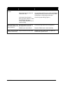
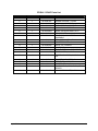
Repeat Time Switch Setting Examples
X1000
0
0
0
1
1
9
Switch Settings
X100
X10
0
0
0
1
1
0
0
0
2
3
9
9
Time Between Samples
X1
3
0
0
0
4
9
3 Seconds (Max. Time)
10 Seconds
100 Seconds
1,000 Seconds
1,234 Seconds
9,999 Seconds
The repeat mode (time-proportional sampling) can be used as a test mode and a backup for the external
input pulse mode (flow-proportional sampling).
Installation and Wiring
The CD20A mounts directly to the C-Series sample probe via the DC-2 coupling. The DC-2 coupling
should be hand-tightened only to ensure that the internal retaining ring is not pushed out of its groove. If
the DC-2 coupling is over-tightened at the CD20A hub, the motor shaft will not engage the DC-1 (not
shown) coupling on the probe.
Use the following steps to install field wiring to the CD20A-115VAC:
1. Connect 115VAC, 50/60 Hz power to 1TB-1 and 1TB-2.
2. Select the pulsed or repeat mode of operation as follows:
a. Connect jumper wire “E1” to 1TB-4 to select the repeat mode.
b. Connect jumper wire “E1” to 1TB-3 to select the pulsed mode of operation.
When the pulsed mode is selected, the flow pulse input must be wired to 1TB-5 (signal) and 1TB-6
(common). If an electronic square wave is utilized, it must have a pulse amplitude of 12VDC. A 5VDC
square wave will not work.
The jumper between 1TB-6 and 1TB-7 adds filter capacitance to the flow pulse input circuit. This jumper
must be in place for input flow pulse rates up to 10Hz. This jumper must be removed when high
frequency flow rate signal inputs (10 to 1000 Hz) are to be utilized.
A +12VDC output is available at 1TB-8 for powering external flow pulse circuiting such as a turbine
meter pre-amplifier. Maximum current from this supply is 50 mA.
2
April 2004