1
Description
The CD20A Control and Drive Assembly is engineered specifically for use with the True-Cut C-Series
sample probes. It comprises the following components:
•
a motor speed control that provides both pulse input (flow-proportional) and repeat (timeproportional) control of the sample probe. When a “start” pulse is received at the CD20A control card
input, the probe is rotated 180 degrees to capture and discharge a single 1.5-ml isokinetic sample. On
a horizontal line, the probe is stopped in the closed position, while on a vertical line, the probe is
stopped in the open position.
•
a 9VDC gear motor with a gear ratio of 150:1
•
a cam with two high points located opposite each other mounted on the gear motor output shaft.
•
a proximity switch mounted in the hub assembly opposite the cam. When a high point on the cam is
opposite the proximity switch, the PROX (“Hold”) LED will be illuminated. This signal indicates the
sample probe is at the stop and “hold” position.
•
a coupling, jam nut, and hub, which allow the CD20A Control and Drive Assembly to be mounted
directly to the C-Series sample probe. No brackets or supports are required, but they are advisable on
pipelines with some vibrations.
•
an explosion-proof housing encloses the complete assembly. Two ¾-in. NPT holes allow connection
of the 115VAC, 50/60 Hz line power and input pulse (for flow proportional sampling). A ½-in.
breather plug is installed on one side of the enclosure, and a ½-in. conduit plug is installed on the
opposite side of the enclosure.
The motor speed control unit allows selection of pulse input (flow-proportional) or repeat (timeproportional) control of the sample probe.
Pulse Input Scaling
The four pulse scaling switches labeled X1000, X100, X10, and X1 allow selection of the desired number
of flow pulses per sample. Some switch setting examples are shown below.
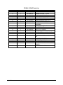
Pulse Input Switch Setting Examples
X1000
0
0
0
1
1
9
X100
0
0
1
0
2
9
X10
0
1
0
0
3
9
X1
1
0
0
0
4
9
Pulses Per Sample
1
10
100
1,000
1,234
9,999
Repeat Time Scaling
The repeat mode utilizes a 1-Hz clock signal in lieu of the external flow proportional pulses to pace the
sample probe.
The X1000, X100, X10, and X1 switches allow direct repeat time settings in seconds. Some repeat time
switch setting examples are shown below.
April 2004
1