1
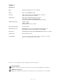
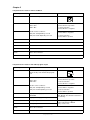
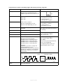
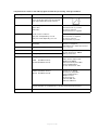
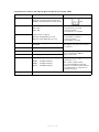
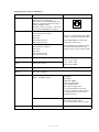
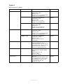
I/O specifications: Actuator with endstop signals and absolute positioning - PWM
Input/Output
Specification
Comments
Description
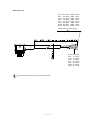
The actuator can be equipped with
electronic circuit that gives an analogue
feedback signal when the actuator moves.
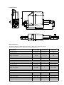
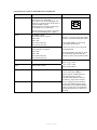
Brown
12-24VDC (+/-)
To extend actuator:
Connect Brown to positive
12V ± 20%
24V ± 10%
Blue
To retract actuator:
Connect Brown to negative
Under normal conditions:
12V, max. 5A depending on load
24V, max. 2.5A depending on load
To extend actuator:
Connect Blue to negative
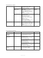
Red
Signal power supply (+)
12-24VDC
Black
Signal power supply GND (-)
Current consumption:
Max. 40mA, also when the actuator is
not running
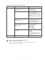
Green
Endstop signal out
Yellow
Endstop signal in
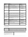
Violet
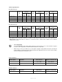
Digital output feedback
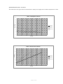
10-90%
White
To retract actuator:
Connect Blue to positive
Output voltage min. VIN - 2V
Source current max. 100 mA
NOT potential free
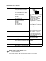
(Feedback level 4)
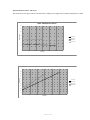
20-80%
(Feedback level 5)
Special
(Feedback level 9)
Not to be connected
Page 13 of 20
Output voltage min. VIN - 2V
Tolerances +/- 2%
Max. current output: 12mA
It is recommendable to have the
actuator to activate its limit switches
on a regular basis, to ensure more
precise positioning