1
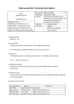
Microcomputer Technical Information
CP(K), O
78K0S/KU1+, 78K0S/KY1+,
78K0S/KA1+, 78K0S/KB1+
Document No.
ZBG-CC-06-0028
Date issued
July 11, 2006
Issued by
1st Solution Group
Multipurpose Microcomputer Systems Division
4th Systems Operations Unit
NEC Electronics Corporation
Usage Restrictions
Related documents
78K0S/KY1+ User’s Manual: U16994EJ3V0UD00
Notification
classification
√
1/1
Usage restriction
Upgrade
78K0S/KA1+ User’s Manual: U16898EJ3V0UD00
Document modification
78K0S/KB1+ User’s Manual: U17446EJ2V0UD00
Other notification
1. Affected products
78K0S/KU1+
μPD78F9200, μPD78F9201, μPD78F9202
78K0S/KY1+
μPD78F9210, μPD78F9211, μPD78F9212
78K0S/KA1+
μPD78F9221, μPD78F9222
78K0S/KB1+
μPD78F9232, μPD78F9234
2. Restriction details
Restriction on using flash self-programming
When using flash self-programming, clear the FLCMD register to 0 immediately before shifting to
normal mode or self-programming mode. In addition, execute NOP and HALT instructions after specific
sequence processing to shift to self-programming mode.
* See the attachment for details on specific sequence processing.
This is a restriction to avoid an operation bug that occurs when the standby function performed by the
HALT instruction and flash self-programming are used together and executed repeatedly.
3. Details on restriction and workaround
See the attachment for details on the restriction and its workaround.
4. Modification plan
This restriction is avoidable by using a software workaround, so the device will not be revised for this
restriction. Please regard this item as a usage restriction.
The user’s manual will be revised with descriptions on the above restriction.
ZBG-CC-06-0028
Attachment - 1/11
Usage Restrictions in 78K0S/KU1+, 78K0S/KY1+, 78K0S/KA1+ and 78K0S/KB1+
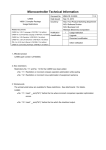
1. Product History
<78K0S/KU1+>
Description
μPD78F9200, μPD78F9201,
μPD78F9202
Δ
Restriction on using flash self-programming
<78K0S/KY1+>
Description
Restriction on using flash self-programming
μPD78F9210, μPD78F9211,
μPD78F9212
Δ
<78K0S/KA1+>
Description
Restriction on using flash self-programming
μPD78F9221, μPD78F9222
Δ
<78K0S/KB1+>
Description
Restriction on using flash self-programming
Remark
μPD78F9232, μPD78F9234
Δ
The meaning of each symbol is as follows.
Δ: Restriction applies (correction is not planned)
2. Restriction Details
• Restriction on using flash self-programming
[Description and cause]
If the standby function performed by the HALT instruction and flash self-programming are used together
using the procedure shown in the figure on the next page, the subsequent operation becomes unexpected.
Specific sequence:
The following two modes are available in these products.
- Normal mode:
The state in which normal operation is executed. Operation enters into a standby state after
execution of the HALT instruction.
- Self-programming mode:
The state in which self-programming commands are executable. After setting commands,
addresses and write data and executing the HALT instruction, self-programming is executed.
The specific sequence described in this document is referring to the register manipulation to switch
these two modes.
ZBG-CC-06-0028
Attachment - 2/11
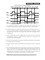
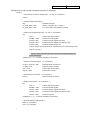
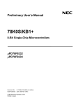
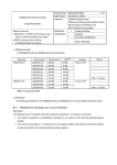
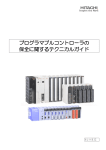
Process Leading up to Unexpected Operation
Normal HALT
execution
Shift to
SELF
Command
setting
SELF
execution
End of
SELF
Normal HALT
execution
Shift to
SELF
Unexpected
operation
HALT
instruction
<3>
<1>
<5>
HALT
execution flag
<2>
<4>
FLSPM
<6>
SELF execution
status
FLCMD
register value
00H
Any command value
<1> An ordinary HALT instruction is executed and the internal HALT execution flag is set.
Self-programming is executed by setting the FLSPM bit while the HALT execution flag is set.
<2> The specific sequence is executed and the operation then enters into self-programming mode. At
this time, the FLSPM bit changes to indicate that self-programming is now executable. However,
self-programming commands are not executed at this time, because the FLCMD register has been
initialized to 00H.
<3> Once a command value is set to the FLCMD register and the HALT instruction is executed, the
self-programming command is executed. The HALT execution flag is cleared just as the
self-programming command is executed.
<4> Execution of the self-programming command is completed, the specific sequence is executed again,
and operation enters into normal mode.
<5> The HALT instruction is executed again, operation enters into standby, and the HALT execution flag
is set.
<6> After the standby state is released, the specific sequence is executed to shift to self-programming
mode. If the command value set to the FLCMD register has not been initialized at this time, the
command still set to the FLCMD register is reexecuted when the FLSPM bit is set.
Self-programming is subsequently executed during CPU operation and the CPU fetches an
incorrect instruction from the flash memory, resulting in an unexpected operation.
Remark The same situation occurs when flash self-programming is executed before <1>.
ZBG-CC-06-0028
Attachment - 3/11
Workaround:
When using flash self-programming, clear the FLCMD register to 0 immediately before shifting to
normal mode or self-programming mode; this prevents execution of illegal commands immediately
after the mode is shifted. In addition, execute NOP and HALT instructions after specific sequence
processing to shift to self-programming mode; this controls the execution timing between the CPU and
the flash memory control block.
The flowcharts and source code examples for the operation bug and its workaround implementation
are described on the following pages.
ZBG-CC-06-0028
Attachment - 4/11
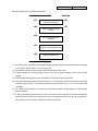
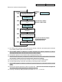
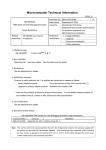
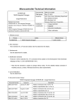
Flowchart leading up to unexpected operation:
1st time
<1>
<2>
<3>
<4>
<5>
2nd time
HALT instruction execution
(standby processing)
Shift to self-programming
mode
<6>
<7>
Sets self-programming
command
HALT instruction execution
(Execution of self-programming)
Shift to normal mode
<1> An ordinary HALT instruction is executed to shift to standby. After that, the standby state is released
by a standby release signal, such as an interrupt.
<2> The specific sequence is executed to shift to self-programming mode.
<3> A self-programming command (block erase in the source code example) is set to the FLCMD
register.
<4> The self-programming command is executed by executing the HALT instruction.
<5> After self-programming processing specified in <3> is completed, the specific sequence is executed
to shift to normal mode. This example presumes that processes from <1> to <5> are performed
repeatedly.
<6> An ordinary HALT instruction is executed to generate a standby release signal, and the standby
state is released.
<7> A self-programming command (block erase in the source code example) is executed immediately
after the specific sequence is executed to shift to self-programming mode for the second time.
Consequently, microcontroller operation becomes unexpected.
ZBG-CC-06-0028
Attachment - 5/11
Example source code causing unexpected operation (assembly language):
MAINLOOP:
; Executes HALT to shift to standby state - <1> and <6> in flowchart
HALT
; Saves the interrupt mask setting before executing self-programming.
DI
MOV
; Disables interrupts
A,MK0
XCH
A,X
MOV
A,MK1
PUSH
AX
MOV
MK0,#0FFH
MOV
MK1,#0FFH
; Saves interrupt mask setting
; Saves only MK0 in KU1+ and KY1+
; Executes the specific sequence to shift to self-programming mode - <2> and <7> in flowchart
ModeOnLoop:
MOV
PFCMD,#0A5H
; Controls PFCMD register
MOV
FLPMC,#01H
; Controls FLPMC register (set value)
MOV
FLPMC,#0FEH
; Controls FLPMC register (inverted set value)
MOV
FLPMC,#01H
; Sets self-programming mode
; When using a clock generated by an external resonator or external input clock, insert a 16 μs wait.
; Operation becomes unexpected when entered into self-programming mode for the second time.
BT
PFS.0,$ModeOnLoop
; Confirms completion of mode shift
; Performs command settings - <3> in flowchart
MOV
A, #0FH
MOV
FLAPH,A
; Sets number of block to be erased
MOV
FLAPHC,A
; Sets compare number for block to be erased (value set to FLAPH)
MOV
FLCMD,#03H
; Sets flash control command (block erase)
MOV
PFS,#00H
; Clears flash status register
MOV
WDTE,#0ACH
; Clears and starts WDT
; Executes erase command - <4> in flowchart
HALT
; Executes self-programming
; Executes the specific sequence to shift to normal mode - <5> in flowchart
ModeOffLoop:
MOV
PFS,#00H
MOV
PFCMD,#0A5H
; Controls PFCMD register
MOV
FLPMC,#00H
; Controls FLPMC register (set value)
MOV
FLPMC,#0FFH
; Controls FLPMC register (inverted set value)
MOV
FLPMC,#00H
; Sets normal mode
BT
PFS.0,$ModeOffLoop
; Confirms completion of mode shift
POP
AX
; Restores interrupt mask setting
MOV
MK1,X
XCH
A,X
MOV
MK0,A
BR
MAINLOOP
ZBG-CC-06-0028
Attachment - 6/11
Example source code causing unexpected operation (C language):
while(1){
/* Executes HALT to shift to standby state - <1> and <6> in flowchart */
HALT();
/* Saves interrupt mask settings */
DI();
// Disables interrupts
ch_mask_bak0 = MK0;
// Saves only MK0 in KU1+ and KY1+
ch_mask_bak1 = MK1;
// ch_mask_bak0/1 are variables for saving
/* Shifts to self-programming mode - <2> and <7> in flowchart */
do{
PFS = 0;
// Clears flash status register
PFCMD = 0xA5;
// Controls PFCMD register
FLPMC = 0x01;
// Controls FLPMC register (set value)
FLPMC = 0xFE;
// Controls FLPMC register (inverted set value)
FLPMC = 0x01;
// Sets self-programming mode
/* When using a clock generated by an external resonator or external input clock,
insert a 16 μs wait.*/
/* Operation becomes unexpected when entered into self-programming mode
for the second time. */
}while(PFS.0 == 1); // Confirms completion of mode shift
/* Performs command settings - <3> in flowchart */
FLAPH = FLAPHC = 0x0F;
// Specifies block to be erased
FLCMD = 0x03;
// Specifies erase command
PFS = 0x00;
// Clears flash status register
WDTE = 0xAC;
// Clears WDT counter
/* Executes erase command - <4> in flowchart */
HALT();
// Executes erase command
/* Shifts to normal mode - <5> in flowchart */
do{
PFS = 0;
// Clears flash status register
PFCMD = 0xA5;
// Controls PFCMD register
FLPMC = 0x00;
// Controls FLPMC register (set value)
FLPMC = 0xFF;
// Controls FLPMC register (inverted set value)
FLPMC = 0x00;
// Sets normal mode
}while(PFS.0 == 1); // Confirms completion of mode shift
/* Restores interrupt mask settings */
MK0 = ch_mask_bak0;
MK1 = ch_mask_bak1;
}
ZBG-CC-06-0028
Attachment - 7/11
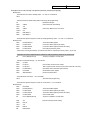
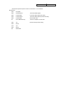
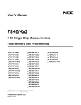
Flowchart of workaround implementation:
1st time
<1>
<2>
<3>
<4>
<5>
<6>
<7>
<8>
HALT instruction execution
(standby processing)
2nd time
<9>
Added processing
FLCMD = 0
Shift to self-programming
mode
* If the CPU clock ≤ 1 MHz, it
will be set to 1 MHz or higher.
NOP, HALT
instruction execution
Sets self-programming
command
HALT instruction execution
(Execution of self-programming)
FLCMD = 0
* If the CPU clock has been changed,
the clock setting before selfprogramming is restored.
Shift to normal mode
<1> An ordinary HALT instruction is executed to shift to standby. After that, the standby state is released
by a standby release signal, such as an interrupt.
<2> The FLCMD register is cleared to 0 before executing the specific sequence to shift to
self-programming mode. The CPU clock is set to 1 MHz or higher.
<3> The specific sequence is executed to shift to self-programming mode.
<4> After the specific sequence (1 assigned to FLPMC for the second time), NOP and HALT instructions
are executed. It takes at most 10 μs until the HALT instruction is released.
<5> A self-programming command (such as write or erase) is set to the FLCMD register.
<6> The self-programming command is executed by executing the HALT instruction.
<7> The FLCMD register is cleared to 0 before the specific sequence is executed to shift to normal
mode.
<8> Execute the specific sequence to shift to normal mode. If the CPU clock has been changed, the
clock setting before self-programming is restored at this time.
<9> This bug is avoided by adding the above processes <2>, <4>, <7> and <8>.
ZBG-CC-06-0028
Attachment - 8/11
Example of source code to which workaround is implemented (assembly language):
MAINLOOP:
; Executes HALT to shift to standby state - <1> and <9> in flowchart
HALT
; Saves the interrupt mask setting before executing self-programming.
DI
; Disables interrupts
MOV
A,MK0
XCH
A,X
MOV
A,MK1
PUSH
AX
MOV
MK0, #0FFH
MOV
MK1, #0FFH
; Saves interrupt mask setting
; Saves only MK0 in KU1+ and KY1+
; Initializes FLCMD register - <2> in flowchart
MOV
FLCMD, #00H
; If CPU clock ≤ 1 MHz, sets CPU clock to 1 MHz or higher.
; Executes the specific sequence to shift to self-programming mode - <3> in flowchart
ModeOnLoop:
MOV
PFCMD,#0A5H
; Controls PFCMD register
MOV
FLPMC,#01H
; Controls FLPMC register (set value)
MOV
FLPMC,#0FEH
; Controls FLPMC register (inverted set value)
MOV
FLPMC,#01H
; Sets self-programming mode
; Executes NOP and HALT instructions - <4> in flowchart
NOP
HALT
; When using a clock generated by an external resonator or external input clock, insert an 8 μs wait.
BT
PFS.0,$ModeOnLoop
; Confirms completion of mode shift
; Performs command settings - <5> in flowchart
MOV
A, #0FH
MOV
FLAPH,A
; Sets number of block to be erased
MOV
FLAPHC,A
; Sets compare number for block to be erased (value set to FLAPH)
MOV
FLCMD,#03H
; Sets flash control command (block erase)
MOV
PFS,#00H
; Clears flash status register
MOV
WDTE,#0ACH
; Clears and starts WDT
; Executes erase command - <6> in flowchart
HALT
; Executes self-programming
; Initializes FLCMD register - <7> in flowchart
MOV
FLCMD, #00H
; If the CPU clock has been changed, the setting before self-programming is restored.
ZBG-CC-06-0028
Attachment - 9/11
; Executes the specific sequence to shift to normal mode - <8> in flowchart
ModeOffLoop:
MOV
PFS,#00H
MOV
PFCMD,#0A5H
; Controls PFCMD register
MOV
FLPMC,#00H
; Controls FLPMC register (set value)
MOV
FLPMC,#0FFH
; Controls FLPMC register (inverted set value)
MOV
FLPMC,#00H
; Sets normal mode
BT
PFS.0,$ModeOffLoop
; Confirms completion of mode shift
POP
AX
; Restores interrupt mask setting
MOV
MK1,X
XCH
A,X
MOV
MK0,A
BR
MAINLOOP
ZBG-CC-06-0028
Attachment - 10/11
Example of source code to which workaround is implemented (C language):
while(1){
/* Executes HALT to shift to standby state - <1> and <9> in flowchart */
HALT();
/* Saves interrupt mask settings */
DI();
// Disables interrupts
ch_mask_bak0 = MK0;
// Saves only MK0 in KU1+ and KY1+
ch_mask_bak1 = MK1;
// ch_mask_bak0/1 are variables for saving
/* Initializes FLCMD register - <2> in flowchart */
FLCMD = 0;
/* If CPU clock ≤ 1 MHz, sets CPU clock to 1 MHz or higher */
/* Enters into self-programming mode - <3> in flowchart */
do{
PFS = 0;
// Clears flash status register
PFCMD = 0xA5;
// Controls PFCMD register
FLPMC = 0x01;
// Controls FLPMC register (set value)
FLPMC = 0xFE;
// Controls FLPMC register (inverted set value)
FLPMC = 0x01;
// Sets self-programming mode
}while(PFS.0 == 1); // Confirms completion of mode shift
/* Executes NOP and HALT instructions - <4> in flowchart */
NOP();
HALT();
/* When using a clock generated by an external resonator or external input clock, insert an 8 μs wait.*/
/* Performs command settings - <5> in flowchart */
FLAPH = FLAPHC = 0x0F;
// Specifies block to be erased
FLCMD = 0x03;
// Specifies erase command
PFS = 0x00;
// Clears flash status register
WDTE = 0xAC;
// Clears WDT counter
/* Executes erase command - <6> in flowchart */
HALT();
// Executes erase command
/* Initializes FLCMD register - <7> in flowchart */
FLCMD = 0;
/* If the CPU clock has been changed, the setting before self-programming is restored. */
/* Shifts to normal mode - <8> in flowchart */
do{
PFS = 0;
// Clears flash status register
PFCMD = 0xA5;
// Controls PFCMD register
ZBG-CC-06-0028
FLPMC = 0x00;
// Controls FLPMC register (set value)
FLPMC = 0xFF;
// Controls FLPMC register (inverted set value)
FLPMC = 0x00;
// Sets normal mode
}while(PFS.0 == 1); // Confirms completion of mode shift
/* Restores interrupt mask settings */
MK0 = ch_mask_bak0;
MK1 = ch_mask_bak1;
}
Attachment - 11/11