1
Microcontroller Technical Information
CP(K), O
QB-MINI2
On-Chip Debug Emulator
with Programming Function
Document No.
ZBG-CD-07-0013
Date issued
January 31, 2007
Issued by
Development Tool Group
Multipurpose Microcomputer Systems Division
4th Systems Operations Unit
NEC Electronics Corporation
Usage Restrictions
Related
documents
Notification
classification
QB-MINI2 User’s Manual:
U18371EJ1V0UM00
√
1/1
Usage restriction
Upgrade
QB-MINI2 Operating Precautions:
Document modification
ZUD-CD-07-0007
Other notification
1. Affected product
Product
QB-MINI2
Generic Name
Control CodeNote
Firmware VersionNote
Remark
MINICUBE2
A
V4.01 or earlier
−
Note See the attachment for the identification method for the control code and firmware version.
2. New restrictions
Restrictions and specification changes No. 14 to No. 18 have been added. See the attachment for
details.
No. 14: Restriction on using QB-MINI2 with USB 1.1 (When using a 78K0R device)
No. 15: Restriction on operation at 20 MHz or higher frequency (When using a 78K0R device)
No. 16: Restriction on general-purpose registers after reset (When using a 78K0R device)
No. 17: Specifications changed/added in conjunction with firmware optimization (When using a
78K0R device)
No. 18: Restriction on hardware breaks (When using a 78K0R device)
3. Workarounds
See the attachment.
4. Modification schedule
Restrictions No. 14, No. 15 and No. 17 have been corrected or implemented in MINICUBE2 firmware
V4.03, which was released on January 29, 2007. Restrictions No. 16 and No. 18 are not planned for
correction.
5. List of restrictions
For the product history and the details of the list of restrictions are described in the attachment.
ZBG-CD-07-0013
Attachment - 1/9
Notes on Using QB-MINI2
This document describes the following items. Refer to the user’s manual of the QB-MINI2 (hereafter
referred to as MINICUBE2) for cautions on using MINICUBE2.
• Restrictions not applicable to the target device but applicable to MINICUBE2
• Restrictions applicable to both the target device and MINICUBE2 but correction is planned only for
MINICUBE2
• Devices supported by MINICUBE2
Refer to the following documents for the restrictions in the target device.
• User’s manual of target device
• Restrictions notification document for target device
• The information in this document is current as of January 2007. The information is subject to
change without notice. For actual design-in, refer to the latest publications of NEC Electronics data
sheets or data books, etc., for the most up-to-date specifications of NEC Electronics products. Not
all products and/or types are available in every country. Please check with an NEC Electronics sales
representative for availability and additional information.
• No part of this document may be copied or reproduced in any form or by any means without the prior
written consent of NEC Electronics. NEC Electronics assumes no responsibility for any errors that may
appear in this document.
• NEC Electronics does not assume any liability for infringement of patents, copyrights or other intellectual
property rights of third parties by or arising from the use of NEC Electronics products listed in this document
or any other liability arising from the use of such products. No license, express, implied or otherwise, is
granted under any patents, copyrights or other intellectual property rights of NEC Electronics or others.
• Descriptions of circuits, software and other related information in this document are provided for illustrative
purposes in semiconductor product operation and application examples. The incorporation of these
circuits, software and information in the design of a customer's equipment shall be done under the full
responsibility of the customer. NEC Electronics assumes no responsibility for any losses incurred by
customers or third parties arising from the use of these circuits, software and information.
• While NEC Electronics endeavors to enhance the quality, reliability and safety of NEC Electronics products,
customers agree and acknowledge that the possibility of defects thereof cannot be eliminated entirely. To
minimize risks of damage to property or injury (including death) to persons arising from defects in NEC
Electronics products, customers must incorporate sufficient safety measures in their design, such as
redundancy, fire-containment and anti-failure features.
• NEC Electronics products are classified into the following three quality grades: "Standard", "Special" and
"Specific".
The "Specific" quality grade applies only to NEC Electronics products developed based on a customerdesignated "quality assurance program" for a specific application. The recommended applications of an NEC
Electronics product depend on its quality grade, as indicated below. Customers must check the quality grade of
each NEC Electronics product before using it in a particular application.
"Standard": Computers, office equipment, communications equipment, test and measurement equipment, audio
and visual equipment, home electronic appliances, machine tools, personal electronic equipment
and industrial robots.
"Special": Transportation equipment (automobiles, trains, ships, etc.), traffic control systems, anti-disaster
systems, anti-crime systems, safety equipment and medical equipment (not specifically designed
for life support).
"Specific": Aircraft, aerospace equipment, submersible repeaters, nuclear reactor control systems, life
support systems and medical equipment for life support, etc.
The quality grade of NEC Electronics products is "Standard" unless otherwise expressly specified in NEC
Electronics data sheets or data books, etc. If customers wish to use NEC Electronics products in applications
not intended by NEC Electronics, they must contact an NEC Electronics sales representative in advance to
determine NEC Electronics' willingness to support a given application.
(Note)
(1) "NEC Electronics" as used in this statement means NEC Electronics Corporation and also includes its
majority-owned subsidiaries.
(2) "NEC Electronics products" means any product developed or manufactured by or for NEC Electronics (as
defined above).
M8E 02. 11-1
ZBG-CD-07-0013
Attachment - 2/9
Product Version
Control CodeNote 1
A
FirmwareNote 2
Remark
V1.00
Newly released
V2.00
Supports V850 microcontrollers
V3.00
Supports 78K0S microcontrollers
V4.00
Supports 78K0R microcontrollers
V4.01
V4.03
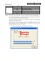
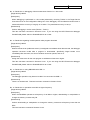
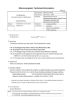
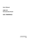
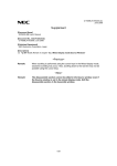
Notes 1. The “control code” is an alphabetic code used to identify the hardware of MINICUBE2. It is
the second digit from the left in the 10-digit serial number printed on the sticker attached to the
bottom side of MINICUBE2 (if it has not been upgraded).
If the product has been upgraded, the control code can be checked with the MINICUBE2
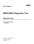
diagnostic tool (see Figure 1 below).
2. Firmware (F/W) is a program embedded in the device in MINICUBE2 for control. The F/W
version is shown as Vx.xx (x is an arbitrary number). The version can be checked with the
MINICUBE2 diagnostic tool (see Figure 1 below).
Figure 1. Checking Control Code and Firmware Version
Control code
Firmware version
ZBG-CD-07-0013
Attachment - 3/9
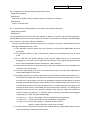
Product History
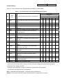
Table 1 is a list of restrictions and changed/added specifications of MINICUBE2.
Table 1. List of Restrictions and Changed/Added Specifications
Control Code
No.
Target
Device
Note
D/P
A
Changed/Added Specifications and Restrictions
F/W Version
V1.00 V2.00 V3.00 V4.00 V4.01 V4.03
1
78K0
D
Internal high-speed RAM values become invalid after
×
×
×
×
×
×
reset
2
V850
D
Restriction regarding watchdog timer
−
×
×
×
×
×
3
V850
D
Restriction on break during subclock operation
−
×
×
×
×
×
4
V850
D
Restriction regarding break during flash macro
−
×
×
×
×
×
servicing
5
V850
D
Restriction regarding reset vector handling function
−
×
×
×
×
×
6
V850
D
Restriction on rewriting registers that require a
−
×
×
×
×
×
Restriction when a reset is generated
−
×
×
×
×
×
Restriction on debugging with operating clock of 6
−
−
×
{
{
{
−
−
×
×
{
{
specific sequence
7
V850
D
8
78K0S
D
MHz or lower
9
78K0S
D
Restriction on downloading when operating clock is
10 MHz
10
78K0S
D
Restriction on display of register values
−
−
×
{
{
{
11
78K0R
D
Restriction on breakpoint for a CPU clock lower than
−
−
−
×
×
Δ
12
78K0R
D
−
−
−
×
×
{
−
−
−
×
×
{
Restriction on using QB-MINI2 with USB 1.1
−
−
−
×
×
{
Restriction on operation at 20 MHz or higher
×
×
×
×
×
{
2 MHz
Restriction on debugging of time measurement
function in 1-wire mode
13
78K0R
D
Restriction regarding invalid operation after program
download
14
78K0R
D
15
78K0
D
frequency
16
78K0R
D
Restriction on general-purpose registers after reset
−
−
−
×
×
×
17
78K0R
D
Specifications changed/added in conjunction with
−
−
−
×
×
{
−
−
−
×
×
×
firmware optimization
18
78K0R
D
Restriction on hardware breaks
{: Restrictions are not applicable or already corrected. Changes or additions of specifications are applied.
Δ: Restrictions are partially corrected.
×: Restrictions are applicable. Changes or additions of specifications are not applied.
−: Not relevant or the target device is not supported
Note D: Applicable during debugging, P: Applicable during programming.
Remark The permanent restriction means a restriction that is not planned for correction.
ZBG-CD-07-0013
Attachment - 4/9
Details of Bugs and Added Specifications
No. 1 Internal high-speed RAM values become invalid after reset
[Target device] 78K0
[Description]
If a reset is input via the RESET pin during program execution, portions in the internal high-speed RAM
areas shown below become invalid. This bug does not apply to reset sources such as the watchdog
timer, LVI, etc.
- 5 bytes from FECBh to FECFh
(When Permit is selected in Target Power OFF field in Configuration dialog box)
- 10 bytes from FEC9h to FECFh and FEDDh to FEDFh
(When Not Permit is selected in Target Power OFF field in Configuration dialog box)
[Workaround]
There is no workaround.
No. 2 Restriction regarding watchdog timer
[Target device] V850
[Description]
The watchdog timer is forcibly stopped by the debug monitor program. Therefore, do not set the option
byte so as to disable stoppage of the watchdog timer. For the option byte setting, see the user’s
manual of the target device.
[Workaround]
There is no workaround.
No. 3 Restriction on break during subclock operation
[Target device] V850
[Description]
When the mode for communication between MINICUBE2 and the target device is UART, and if a break
occurs during subclock operation while the main clock has been stopped, the debug monitor program
forcibly switches the operating clock to the main clock. The device continues its operation with the
main clock, even after execution is resumed. Whether the operating clock during a break is switched
from the subclock to main clock depends on the Main Clock area setting in the Configuration dialog box
of the debugger.
[Workaround]
There is no workaround.
No. 4 Restriction regarding break during flash macro servicing
[Target device] V850
[Description]
If a break occurs during flash macro servicing, it occurs at an unexpected address. This also applies to
the case where a break occurs in the debugger, such as when using the pseudo RRM function.
ZBG-CD-07-0013
Attachment - 5/9
[Workaround]
There is no workaround. Reset the device and reexecute the program.
No. 5 Restriction regarding reset vector handling function
[Target device] V850
[Description]
The reset vector handling function is not supported.
[Workaround]
There is no workaround.
No. 6 Restriction on rewriting registers that require a specific sequence
[Target device] V850
[Description]
Peripheral I/O registers (other than PCC and CKC) that require a specific sequence cannot be rewritten
in the I/O register window or the like in the debugger.
[Workaround]
There is no workaround.
No. 7 Restriction when a reset is generated
[Target device] V850
[Description]
A break occurs when an external reset (when reset is not masked) or an internal reset is generated.
[Workaround]
There is no workaround.
No. 8 Restriction on debugging with operating clock of 6 MHz or lower
[Target device] 78K0S
[Description]
The debugger does not start when the target device operating frequency is 6 MHz or lower.
[Workaround]
There is no workaround. This item has been corrected in firmware V4.00.
No. 9 Restriction on downloading when operating clock is 10 MHz
[Target device] 78K0S
[Description]
When the target device operating frequency is 10 MHz, an error will occur during download of a
program and the downloading cannot be completed.
[Workaround]
There is no workaround.
This item has been corrected in firmware V4.01. If you are using the NEC Electronics debugger
ZBG-CD-07-0013
Attachment - 6/9
ID78K0S-QB, please switch to ID78K0S-QB V2.90 or later.
No. 10 Restriction on display of register values
[Target device] 78K0S
[Description]
The register values may be displayed incorrectly in the debugger during a break.
[Workaround]
There is no workaround. This item has been corrected in firmware V4.00.
No. 11 Restriction on breakpoint for a CPU clock lower than 2 MHz
[Target device] 78K0R
[Description]
If a break occurs during operation at a CPU clock (fCLK) lower than 2 MHz while the PER0 and PER1
registers are set to 0, the internal flash memory can no longer be rewritten. Consequently, the following
operations cannot be performed.
<1> Writing to internal flash memory
<2> Setting or canceling of software breakpoint
<3> Starting execution at the set software breakpoint position
<4> Step-wise execution at the set software breakpoint position
<5> Step-wise execution, Return Out execution
<6> Come Here
<7> If Permit is selected in the Flash Programming area in the Configuration dialog box, the
following operations cannot be performed.
(a) Setting, changing, or canceling of hardware breaks
(b) Masking/unmasking of internal reset
(c) Switching of peripheral breaks
[Workaround]
There is no workaround. To set a breakpoint for operation performed at a CPU clock lower than 2 MHz,
use a hardware break, not a software break.
With firmware V4.03, this restriction is corrected partially, as shown below. To apply this correction,
please use the NEC Electronics debugger ID78K0R-QB V3.30 or later.
[Correction]
For clock frequencies with which flash memory cannot be written, specifications will be changed so that
the frequency that enables flash memory rewriting is selected automatically, and the register settings
are restored after flash memory rewriting is completed. To prevent the frequency from being switched
automatically, select “User” in the Monitor Clock area and “Not Permit” in the Flash Programming area
in the ID78K0R-QB Configuration dialog box. However, operations <1> to <7> shown above can no
longer be performed.
ZBG-CD-07-0013
Attachment - 7/9
No. 12 Restriction on debugging of time measurement function in 1-wire mode
[Target device] 78K0R
[Description]
When debugging is performed in 1-wire mode (selected by choosing TOOL0 in the Target Device
Connection area in the Configuration dialog box of the debugger), the Run-Break execution time is
measured with the accuracy of roughly 10 ms order. The prescribed accuracy is 100 μs.
[Workaround]
Perform debugging in 2-wire mode (TOOL0 + TOOL1).
This item has been corrected in firmware V4.03. If you are using the NEC Electronics debugger
ID78K0R-QB, please switch to ID78K0R-QB V3.30 or later.
No. 13 Restriction regarding invalid operation after program download
[Target device] 78K0R
[Description]
When the reset vector (addresses 0 and 1) is assigned to an address lower than 0x0100, the debugger
operation becomes invalid after a program is downloaded. Specifically, illegal breaks occur
immediately after execution, the Source window cannot be opened, and so on.
[Workaround]
Assign the reset vector for the user program to addresses of 0x0100 or higher.
This item has been corrected in firmware V4.03. If you are using the NEC Electronics debugger
ID78K0R-QB, please switch to ID78K0R-QB V3.30 or later.
No. 14 Restriction on using QB-MINI2 with USB 1.1
[Target device] 78K0R
[Description]
The debugger operation may become invalid if it is connected via USB 1.1.
[Workaround]
There is no workaround. This item has been corrected in firmware V4.03.
No. 15 Restriction on operation at 20 MHz or higher frequency
[Target device] 78K0R
[Description]
When the QB-MINI2 operates at a frequency of 20 MHz or higher, downloading or manipulation to
change the memory contents may fail.
[Workaround]
Perform downloading or manipulation to change the memory contents at a frequency lower than 20
MHz.
This item has been corrected in firmware V4.03.
ZBG-CD-07-0013
Attachment - 8/9
No. 16 Restriction on general-purpose registers after reset
[Target device] 78K0R
[Description]
After reset in standby mode, the general register contents are not retained.
[Workaround]
There is no workaround.
No. 17 Specifications changed/added in conjunction with firmware optimization
[Target device] 78K0R
[Description]
The specifications shown below have been changed or added in conjunction with firmware optimization.
See QB-MINI2 Operating Precautions (ZUD-CD-07-0007) for information on changes in the MINICUBE2
user’s manual in conjunction with this modification.
This item has been implemented in firmware V4.03. To apply this correction, use the NEC Electronics
debugger ID78K0R-QB V3.30 or later.
<1> The debugger operation speed has been improved by improving the MINICUBE2 firmware
processing.
<2> The operation speed in 1-wire mode has been improved to be equalized with that in 2-wire
mode.
<3> For a case when the pseudo real-time monitor function (RRM function) is not used during
debugging in 2-wire mode, the occupied size of the debug monitor program allocated to the last
block in the internal ROM has been reduced from 1 KB to 88 bytes.
<4> Instructions that perform two instructions during step-wise execution have been modified so as
to perform only one instruction.
<5> The option byte setting (C1H) for the LVI default start function is now the same regardless of
whether MINICUBE2 is connected.
<6> Debugger operations for rewriting the flash memory (download, software break setting, etc.),
which were not possible when the target microcontroller cannot rewrite the flash memory due to
the CPU clock or the regulator mode, are now available by changing the specification so that the
debugger automatically changes the SFR contents so as to enable rewriting of the flash memory
to enable such operations. (Correction of restriction No. 11 is also included in this change). After
rewriting the flash memory is completed, the SFR contents will be restored. The debugger will
output the following errors if the operation voltage is lower than the voltage with which flash
memory rewriting is possible (1), or if the flash memory rewriting is prohibited by the debugger
configuration (2). (When using the ID78K0R-QB)
• In case of (1): “F0C37: The voltage is too low to operate flash programming.”
• In case of (2): “F0C48: Flash programming is disabled in the debugger.”
• In case of (1) or (2) and when setting or cancelling software breaks:
“W401C: Software break can not be set on this area.”
<7> A break, which was generated if STOP mode is entered when the pseudo RRM function is used,
is now prevented by releasing the STOP mode.
ZBG-CD-07-0013
Attachment - 9/9
No. 18 Restriction on hardware breaks
[Target device] 78K0R
[Description]
A hardware break occurs at an address several instructions after the specified point. This applies to
both instruction fetch and data access. If any of the following debugger operations <1> to <3> is
performed while the flash memory cannot be rewritten, a hardware break occurs at an address several
instructions after the specified point.
<1> Step-wise execution
<2> Return Out execution
<3> Come Here
[Workaround]
There is no workaround.