1
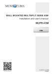
ACZCI
4H4R09
ACZEM4H4R09
ACZCI
4H4R12
ACZEM4H4R12
Content
Operation and Maintenance
Operation Guide
Operation Notices
Precautions
1
Parts name
2
Maintenance
Clean and maintenance 7
Malfunction
General phenomenon
analysis
9
Error code
11
Names and functions of wireless remote control
3
Guide for operation-General operation
5
Guide for operation-Optional operation
5
Introduction for special function
5
Changing batteries and notices
5
Emergency operation
6
Installation
Installation Notice
Installation dimension diagram
Tools for installation
Selection of installation location
Requirements for electric connection
12
13
13
14
Installation
Installation of indoor unit
Installation of outdoor unit
Vacuum pumping
Leakage detection
Check after installation
Test operation
15
18
20
21
21
22
Attachment
Configuration of connection pipe
23
Operation Notices
Precautions
Warning
● Do not connect air conditioner to multipurpose socket.Otherwise, it may cause fire
hazard.
● Do not step on top panel of outdoor unit, or
put heavy objects. It may cause damage or
personal injury.
● Please disconnect power supply when
cleaning air conditioner. Otherwise, it may
cause electric shock.
● Do not extend fingers or objects into air inlet
or air outlet. It may cause personal injury or
damage.
● Do not spray water on indoor unit. It may
cause electric shock or malfunction.
● Air Conditioner should be properly grounded.
Incorrect grounding may cause electric
shock.
● Do not repair air conditioner by yourself. It
● Do install the air switch. If not, it may cause
may cause electric shock or damage. Please
malfunction.
contact dealer when you need to repair air
conditioner.
● Do not block air outlet or air inlet. It may
cause malfunction.
● Installation and maintenance must be
performed by qualified professionals.
Otherwise, it may cause personal injury or
damage.
● If you need to relocate air conditioner to
another place, only the qualified person can
perform the work. Otherwise, it may cause
personal injury or damage.
Working temperature range
Indoor side Outdoor side
DB/WB(℃ ) DB/WB(℃ )
Maximum
cooling
Maximum
heating
32/23
43/26
27/-
24/18
● The operating temperature range (outdoor
temperature) for cooling only unit is 18℃ ~
43℃ ;for heat pump unit is -7℃ ~ 43℃ .
1
Parts name
air inlet
Indoor unit
panel
aux.button
horizontal
louver
air outlet
display
cooling
power
receiver
indicator
indicator
window
drying
heating
temp.
indicator
indicator
indicator
remote
control
(Display content or position may be different from above
graphics, please refer to actual products)
Outdoor unit
air inlet
handle
air outlet
Notice:
● Actual product may be different from above graphics, please refer to
actual products.
2
OPERATION OF WIRELESS REMOTE CONTROL
Notice: This is a general use remote controller, it could be used for the air conditioners with multifunction;
For some function, which the model doesn't have, if press the corresponding button on the remote controller
that the unit will keep the original running status.
Names and functions of wireless remote control
Note: Be sure that there are noobstructions between receiver and remote controller; Don't drop or throw
the remote control; Don't let any liquid in the remote control and put the remote control directly under the
sunlight or any place where is very hot. Remark: Any operate and explain for heating in this manual is
only for cooling and heating unit, but this is a cooling only unit, so it is not available on this unit.
Signal transmitter
Note:Swing mode is not available on this unit
Note: Heat mode is not
available on this unit
SLEEP
SLEEP button
●
FAN
FAN button
●
ON/OFF button
●
MODE
Press this button, the unit will be turned on,
press it once more, the unit will be turned
off. When turning on or turning off the unit,
the Timer, Sleep function will be canceled,
but the presetting time is still remained.
AUTO
Press this button, Auto, Cool,Dry, Fan,
Heat mode can be selected circularly.
Auto mode is default while power on.
Under Automode,the temperature will not
be displayed; Under oHeatmode, the
o
initial value is 28 C (82 F); Under other
o
o
modes,the initial value is 25 C( 77 F).
AUTO
▲ ▲ ▲▲ ▲
HEAT
DRY
COOL
FAN
AUTO
COOL
DRY
FAN
HEAT
By pressing this key,you may select AUTO,
FAN 1, FAN 2, FAN 3 or FAN 4, and may also
cycle between them. FAN 4 only in cool mode.
After being energized, AUTO is defaulted. Only
LOW fan can be set under DRY mode, pressing
this key can not adjust the fan sreed, but can send
message.
(Note:When select Fan 4, the fan speed is
same as fan3 on this unit)
MODE button
●
Off can be selected. After powered on,Sleep
Off is defaulted. After the unit is turned off,
the Sleep function is canceled. After Sleep
function set up, the signal of Sleep will display.
In this mode,the time of timer can be adjusted.
Under Fan and Auto modes, this function is
not available.
Remote control
ON/OFF
Press this button, Sleep On and Sleep
(Only for cooling and heating.unit
As for cooling only unit, it won’t have
anyaction when it receives the signal
of heating operation.)
3
SWING
Fan 1
Fan 2
Fan 3
Fan 4
SWING button
●
Note:Not available on this unit
Press this key to activate or deactivate
the swing.
OPERATION OF WIRELESS REMOTE CONTROL
TIMER
TIMER button
By pressing this key under switch-off state,you
may set the time for auto switch-on. The range of
setting is 0.5 ~ 24 hours. The characters "T-ON"
and "H" will flash for 5 seconds. Within 5 seconds,
you may make one press of this key to complete
the sttingand send the message.If the setting is
valid, the set time will be displayed for 2 seconds
before display of the temperature message.During
flash,you may press "+" key to increase the value
and press "-" key to decrease the value. The time will
increase or decrease by 0.5 hours with each press
of this key.If pressing "+" or "-" key continuously,
the time value will change rapidly.The remote con
troller can increase the set time by 0.5 hours every
0.25 seconds. After being energized, the fault is no
timer setting, and there is no display of "T-ON" or
"H". Press ON/OFF key to switch on the unit and
cancel the auto switch-on.When the temperature
display becomes constant, you maypress this key
again to display the remaining set time. The time value,
"T-On" and "H" will display constantly for 2 seconds.
After 2 seconds,the preset temperature will be displayed.
within these 2 seconds,you may press this key again to
cancel the auto switch-on and send the message.you may.
● By pressing this key under switch-on state, set the
time for auto switch-off.
The method of setting as the same as for auto switch-on.
●
Remote control
+
+ button
●
For presetting temperature increasing.
Press this button,can set up the temperature,
when unit is on. Continuously press and
hold this button for more than 2 seconds,
the corresponding contents will be
changed rapidly, until unpress the button
then send the information, C ( F ) is displaying all along. In Auto mode, the temperature can not be set up, but operate this
button can send the signal. Centigrade
setting range :16-30; Fahrenheit scale
setting range 61-86.
●
Presetting temperature can be decreased.
Press this button, the temperature can be
set up, continuously press this button and hold
for two seconds, the relative contents can
quickly change, until unhold this button
and send the order that the C ( F) signal
will be displayed all the time. The
temperature adjustment is unavailable
under the Auto mode, but the order can
be sent by if pressing this button.
-
- button
4
OPERATION OF WIRELESS REMOTE CONTROL
Guide for operation-General operation
1. After powered on, press ON/OFF button, the unit will start to run.
2. Press MODE button, select desired running mode.
3. Pressing + or - button, to set the desired temperature. (It is unnecessary
set the temp. at AUTO mode.)
4. Pressing FAN button, set fan speed, can select AUTO, FAN 1, FAN 2,
FAN 3 or FAN 4.
(Note:When select Fan 4, the fan speed is same as fan3 on this unit)
5. Pressing SWING button, to select the swing. (Note: Not available on this unit)
Guide for operation-Optional operation
1. Press SLEEP button, to set sleep.
2. Press TIMER button, can set the scheduled timer on or timer off.
Introduction for special function
★ About AUTO RUN
When AUTO RUN mode is selected, the setting temperature will not be
displayed on the LCD, the unit will be in accordance with the room temp.
automatically to select the suitable running method and to make ambient
comfortable.
★ About LOCK
Under switch-on or switch-off state, you may hold "+" and "-" key
simultaneously to lock and unlock the keypad. When locked, the display
will show the LOCK icon, in which case the lock icon will flash three times
upon operation of any key. After the keypad is unlocked, the lock icon on
the display will be hidden. After being energized, the default is unlock.
★ About switch between Fahrenheit and Centigrade
Under switch-off state, you may hold "-" and "MODE" keys simultaneously to
switch between ℃ and ℉.
★ About Lamp
Under switch-on or switch-off state, you may hold "+" and "FAN" key simultaneously for 3
seconds to set the lamp on or off and send the code. After being energized, the lamp is
defaulted on.
Changing batteries and notices
1.
Slightly to press the place
to take out the back cover of wireless
remote control.(As shown in figure)
2. Take out the old batteries. (As show in figure)
3. Insert two new AAA1.5V dry batteries, and pay attention to the polarity.
(As show in figure)
4. Attach the back cover of wireless remote control. (As show in figure)
★ NOTE:
●
●
When changing the batteries, do not use the old or different batteries,
otherwise, it can cause the malfunction of the wireless remote control.
If the wireless remote control will not be used for a long time, please
take them out, and don't let the leakage liquid damage the wireless
remote control.
●
The operation should be in its receiving range.
●
It should be placed at where is 1m away from the TV set or stereo sound sets
●
If the wireless remote control can not operate normally, please take them out,
after 30s later and reinsert, if they cannot normally run, please change them.
5
.
Emergency operation
If remote controller is lost or damaged, please use auxiliary
button to turn on or turn off the air conditioner. The
operation in details are as below:
As shown in the fig. Open panel, press aux. button
to turn on or turn off the air conditioner. When the
air conditioner is turned on, it will operate under auto mode.
6
panel
aux.
button
Maintenance
Clean and maintenance
Note:
● Turn off the air conditioner and disconnect the power before cleaning the air conditioner to
avoid electric shock.
● Do not wash the air conditioner with water to avoid electric shock.
● Do not use volatile liquid to clean the air conditioner.
Clean surface of indoor unit
When the surface of indoor unit is dirty, it is recommended to use a soft dry cloth or wet cloth to
wipe it.
Note:
● Do not remove the panel when cleaning it.
Clean filter
1. Open panel
Pull out the panel to a certain angle as shown in the fig.
2. Remove filter
Remove the filter as indicated in the fig.
3. Clean filter
● Use dust catcher or water to clean the filter.
● When the filter is very dirty, use the water (below 45℃ )
to clean it, and then put it in a shady and cool place to
dry.
4. Install filter
Install the filter and then close the panel cover tightly.
Note:
● The filter should be cleaned every three months. If there is much dust in the operation
environment, cleaning frequency can be increased.
● After removing the filter, do not touch fins to avoid injury.
● Do not use fire or hair dryer to dry the filter to avoid deformation or fire hazard.
7
Checking before use-season
1. Check whether air inlet and air outlet are blocked.
2. Check whether air switch is in good condition.
3. Check whether filter is clean.
4. Check whether mounting bracket for outdoor unit is damaged or
corroded. If yes, please contact dealer.
5. Check whether drainage pipe is damaged.
Checking after use-season
1. Disconnect power supply.
2. Clean filter and indoor unit’s panel.
3. Check whether mounting bracket for outdoor unit is damaged or
corroded. If yes, please contact dealer.
Notice for recovery
1. Many packing materials are recyclable materials.
Please dispose them in appropriate recycling unit.
2. If you want to dispose the air conditioner, please contact local dealer
or consultant service center for the correct disposal method.
8
Malfunction
General phenomenon analysis
Please check below items before asking for maintenance. If the malfunction still can’t be
eliminated, please contact local dealer or qualified professionals.
Phenomenon
Check items
Solution
Indoor unit can’t ● Whether it's interfered severely
receive remote (such as static electricity, stable
controller’s
voltage)?
signal or remote ● Whether remote controller is
controller has within the signal receiving range?
no action.
● Whether there are obstacles?
● Whether remote controller is
pointing at the receiving window?
● Cut off the power supply.
Turn on the power after about
3 minutes turn on the unit again.
● Signal receiving range is 8m.
● Remove obstacles.
● Select proper angle and point
the remote controller at the
receiving window on indoor unit.
● Is sensitivity of remote controller ● Check the batteries. If the
low; fuzzy display and no display? power of batteries is too low,
please replace them.
● No display when operating
remote controller?
● Fluorescent lamp in room?
Air conditioner
can’t operate
● Power failure?
● Check whether remote
controller appears to be
damaged. If yes, replace it.
● Take the remote controller
close to indoor unit.
● Turn off the fluoresent lamp
and then try it again.
● wait until power recovery.
● Air switch trips off or fuse is burnt ● Ask professional to replace air
out?
switch or fuse.
● Wiring has malfunction?
● Ask professional to replace it.
● Unit has restarted immediately
after stopping operation?
● Wait for 3min, and then turn on
the unit again.
● Whether the function setting for ● Reset the function.
remote controller is correct?
Mist is emitted ● Indoor temperature and humidity ● Because indoor air is cooled
is high?
rapidly. After a while, indoor
from indoor
temperature and humidity will be
unit’s air outlet
decrease and mist will disappear.
9
Phenomenon
Check items
Solution
No air emitted ● Air inlet or air outlet of indoor unit
from indoor unit is blocked?
● Under heating mode, indoor
temperature is reached to set
temperature?
● Heating mode is turned on just
now?
Set temperature ● Unit is operating under auto
mode?
can’t be
adjusted
● Eliminate obstacles.
● After reaching to set
temperature, indoor unit will stop
blowing out air.
● In order to prevent blowing out
cold air, indoor unit will be started
after delaying for several minutes,
which is a normal phenomenon.
● Temperature can’t be adjusted
under auto mode. Please switch
the operation mode if you need to
adjust temperature.
● Your required temperature
● Set temperature range:
exceeds the set temperature range? 16℃ ~30℃ .
● Voltage is too low?
● Wait until the voltage resumes
Cooling
normal.
(heating) effect
is not good.
● Filter is dirty?
● Clean the filter.
● Set temperature is in proper
range?
● Door and window are open?
● Adjust temperature to proper
range.
● Close door and window.
Odours are
emitted
● Whether there’s odour source,
● Eliminate the odour source.
such as furniture and cigarette, etc. ● Clean the filter.
Air conditioner
operates
normally
suddenly
● Whether there’s interference,
such as thunder, wireless devices,
etc.
Outdoor unit has ● Heating mode is turned on?
vapor
“Water flowing” ● Air conditioner is turned on or
turned off just now?
noise
Cracking noise ● Air conditioner is turned on or
turned off just now?
10
● Disconnect power, put back
power, and then turn on the unit
again.
● During defrosting under
heating mode, it may generate
vapor, which is a normal
phenomenon.
● The noise is the sound of
refrigerant flowing inside the unit,
which is a normal phenomenon.
● This is the sound of friction
caused by expansion and/or
contraction of panel or other parts
due to the change of temperature.
Error code
● When air conditioner status is abnormal, temperature indictor on indoor unit will blink to
display corresponding error code. Please refer to below list for identification of error code.
Error code
Troubleshooting
H1
Means defrosting status. It’s the normal phenomenon.
E5
C5
It can be eliminated after restarting the unit. If not ,
please contact qualified professionals for service.
It can be eliminated after restarting the unit. If not,please
contact qualified professionals for service.
It can be eliminated after restarting the unit. If not,please
contact qualified professionals for service.
It can be eliminated after restarting the unit. If not,please
contact qualified professionals for service.
Please contact qualified professionals for service.
F1
Please contact qualified professionals for service.
F2
Please contact qualified professionals for service.
H4
U8
H6
Indoor display
Error code
● Above indicator diagram is only for reference. Please refer to actual product for the actual
indicator and position.
Warning
● When below phenomenon occurs, please turn off air conditioner and disconnect power
immediately, and then contact the dealer or qualified professionals for service.
Phenomenon
Power cord is overheating or damaged.
There’s abnormal sound during operation.
Air switch trips off frequently.
Air conditioner gives off burning smell.
Indoor unit is leaking
● Do not repair or refit the air conditioner by yourself.
● If the air conditioner operates under abnormal conditions, it may cause malfunction, electric
shock or fire hazard.
11
Installation Notice
At least 15cm
Space to the ceiling
Installation dimension diagram
Space to the wall
Space to the wall
At least 15cm
Space to the obstruction
e
ov
Ab
Space to the wall
Space to the wall
cm
Air inlet side
cm
30
30cm Above
0
20
50cm Above
At least 230cm
At
Sp
a
ce
to
t
he
ob
str
u
Space to the floor
ctio
lea
n
st 3
00
cm
At least 15cm
50cm Above
e
ov
Ab
Drainage pipe
Air outlet side
12
Tools for installation
1 Level meter
2 Screw driver
3 Impact drill
4 Drill head
5 Pipe expander
6 Torque wrench
7 Open-end wrench
Note:
4.Select a location which is out of reach for
children.
8 Inner hexagon
spanner
9 Leakage detector
10 Vacuum pump
11 Pressure meter
12 Universal meter
13 Pipe cutter
14 Measuring tape
5.The location should be able to withstand the
weight of indoor unit and won't increase
noise and vibration.
6.The height of indoor unit should be between
230-260cm from the floor in order to provide
sufficient space for maintenance.
● Please contact the local agent for installation.
● Don't use unqualified power cord.
Selection of installation location
Basic requirement
7.Don't install the indoor unit right above the
electric appliance.
8.The appliance shall not be installed in the
laundry
Outdoor unit
1.Select a location where the noise and
outflow air emitted by the outdoor unit will
not affect neighborhood.
Installing the unit in the following places may
cause malfunction. If it is unavoidable, please
consult the local dealer:
2.The location should be well ventilated
and dry, in which the outdoor unit won't be
exposed directly to sunlight or strong wind.
1.The place near strong heat sources, vapors,
flammable or explosive gas, or volatile
objects spread in the air.
3.The location should be able to withstand the
weight of outdoor unit.
2.The place with high-frequency devices (such
as welding machine, medical equipment).
4.Make sure that the installation follows the
requirement of installation dimension
diagram.
3.The place near coast area.
4.The place with oil or fumes in the air.
5.Select a location which is out of reach for
children and far away from animals or
plants.If it is unavoidable, please add
fence for safety purpose.
5.The place with sulfureted gas.
6.Other places with special circumstances.
Indoor unit
1.There should be no obstruction near air inlet
and air outlet.
2.Select a location where the condensation
water can be dispersed easily and won't
affect other people.
3.Select a location which is convenient to
connect the outdoor unit and near the power
socket.
13
Requirements for
electric connection
Safety precaution
1.Must follow the electric safety regulations
when installing the unit.
2.According to the local safety regulations,
use qualified power supply circuit and air
switch.
3.Make sure the power supply matches
with the requirement of air conditioner.
Unstable power supply or incorrect wiring
may result in electric shock,fire hazard or
malfunction. Please install proper power
supply cables before using the air
conditioner.
4.Properly connect the live wire, neutral wire
and grounding wire of power socket.
5.Be sure to cut off the power supply before
proceeding any work related to electricity
and safety.
6.Do not put through the power before
finishing installation.
7.For appliances with type Y attachment,the
instructions shall contain the substance of
thefollowing.If the supply cord is damaged,it
must be replaced by the manufacturer,its
service agent or similarly qualified persons
in order to avoid a hazard.
Grounding requirement
1.The air conditioner is first class electric
appliance. It must be properly grounding
with specialized grounding device by a
professional. Please make sure it is always
grounded effectively, otherwise it may cause
electric shock.
2.The yellow-green wire in air conditioner is
grounding wire, which can't be used for other
purposes.
3.The grounding resistance should comply with
national electric safety regulations.
4.The appliance must be positioned so that the
air switch
is accessible
5.An all-pole disconnection switch having a
contact separation of at least 3mm in all poles
should be connected in fixed wiring
6.Including an air switch with suitable capacity,
please note the following table. Air switch
should be included magnet buckle and
heating buckle function, it can protect the
circuit-short and overload. (Caution: please
do not use the fuse only for protect the circuit)
AirAir switch capacity
conditioner
09K
10A
12K
16A
8.The temperature of refrigerant circuit will be
high, please keep the interconnection cable
away from the copper tube.
14
Installation
Installation of indoor unit
Step one: choosing installation
location
Piping hole
Recommend the installation location to the
client and then confirm it with the client.
φ55
φ70
Step two: install wall-mounting frame
1.Hang the wall-mounting frame on the wall;
adjust it in horizontal position with the level
meter and then point out the screw fixing
holes on the wall.
2.Drill the screw fixing holes on the wall with
impact drill (the specification of drill head
should be the same as the plastic expansion
particle) and then fill the plastic expansion
particles in the holes.
3.Fix the wall-mounting frame on the wall
with tapping screws (ST4.2X25TA) and then
check if the frame is firmly installed by
pulling the frame. If the plastic expansion
particle is loose, please drill another fixing
hole nearby.
Note:
● Pay attention to dust prevention and take
relevant safety measures when opening the
hole.
● The plastic expansion particles are not
provided and should be bought locally.
Step four: outlet pipe
1.The pipe can be led out in the direction of
right, rear right, left or rear left.
Step three: open piping hole
1.Choose the position of piping hole according
to the direction of outlet pipe. The position
of piping hole should be a little lower than
the wall-mounted frame, shown as below.
Wall
Space
to the
wall
above
150mm
Mark in the middle of it
Left
55mm
Rear piping hole
Level meter
Wall
Space
to the
wall
above
150mm
5-10
left
rear right
right
rear left
2.When selecting leading out the pipe from left
or right, please cut off the corresponding
hole on the bottom case.
left
right
Right
55mm
Rear piping hole
cut off
the hole
2.Open a piping hole with the diameter of
φ55 or φ70 on the selected outlet pipe
position.In order to drain smoothly, slant the
piping hole on the wall slightly downward to
the outdoor side with the gradient of 5-10°.
Indoor
Model
Cooling capacity <
6000W
Cooling
capacity ≥ 6000W
outdoor
55 or
70
15
Step five: connect the pipe of indoor
unit
1.Aim the pipe joint at the corresponding
bellmouth.
pipe joint
union nut
Step six: install drain hose
1.Connect the drain hose to the outlet pipe of
indoor unit.
pipe
outlet
pipe
2.Bind the joint with tape.
2.Pretightening the union nut with hand.
3.Adjust the torque force by referring to the
following sheet. Place the open-end wrench
on the pipe joint and place the torque
wrench on the union nut. Tighten the union
nut with torque wrench.
outlet pipe
drain hose
tape
Note:
open-end
wrench
● Add insulating pipe in the indoor drain hose
in order to prevent condensation.
● The plastic expansion particles are not
provided.
union nut
torque wrench
drain hose
pipe
drain hose
indoor pipe
Hex nut diameter
Ф
Ф Ф Ф Ф Tightening
torque
1gP
̚
̚
̚
̚
̚
insulating pipe
4.Wrap the indoor pipe and joint of connection
pipe with insulating pipe, and then wrap it
with tape.
Step seven: connect wire of indoor
unit
1.Open the panel, remove the screw on the
wiring cover and then take down the cover.
panel
screw
insulating pipe
wiring cover
16
2.Make the power connection wire go through
the cable-cross hole at the back of indoor
unit and then pull it out from the front side.
● For the air conditioner without plug, an air
switch must be installed in the line. The
air switch should be all-pole parting and the
contact parting distance should be more
than 3mm.
cable-cross
hole
Step eight: bind up pipe
1.Bind up the connection pipe, power cord
and drain hose with the band.
power connection
wire
3.Remove the wire clip; connect the power
connection wire to the wiring terminal ;
tighten the screw and then fix the power
connection wire with wire clip.
indoor unit
gas
pipe
indoor and
outdoor power cord
liquid pipe
band
drain hose
Wiring Cover
N(1)
2
3
2.Reserve a certain length of drain hose and
power cord for installation when binding
them. When binding to a certain degree,
separate the indoor power and then
separate the drain hose.
Outdoor unit connection
connection pipe
drain hose
band
4.Put wiring cover back and then tighten the
screw.
5.Close the panel.
indoor power cord
Note:
● All wires of indoor unit and outdoor unit
should be connected by a professional.
● If the length of power connection wire is
insufficient, please contact the supplier for a
new one. Avoid extending the wire by yourself.
● For the air conditioner with plug, the plug
should be reachable after finishing installation.
3.Bind them evenly.
4.The liquid pipe and gas pipe should be
bound separately at the end.
Note:
● The power cord and control wire can't be
crossed or winding.
● The drain hose should be bound at the
bottom.
17
Installation of outdoor unit
Step nine: hang the indoor unit
1.Put the bound pipes in the wall pipe and
then make them pass through the wall hole.
2.Hang the indoor unit on the wall-mounting
frame.
1.Select installation location according to the
house structure.
3.Stuff the gap between pipes and wall hole
with sealing gum.
2.Fix the support of outdoor unit on the
selected location with expansion screws.
4.Fix the wall pipe.
indoor
wall pipe
Step one: fix the support of outdoor
unit(select it according to the actual
installation situation)
Note:
outdoor
●Take sufficient protective measures when
installing the outdoor unit.
●Make sure the support can withstand at least
four times the unit weight.
●The outdoor unit should be installed at least
3cm above the floor in order to install drain
joint.
●For the unit with cooling capacity of
2300W~5000W, 6 expansion screws are
needed; for the unit with cooling capacity
of 6000W~8000W, 8 expansion screws are
needed; for the unit with cooling capacity of
10000W~16000W, 10 expansion screws are
needed.
sealing gum
5.Check if the indoor unit is installed firmly
and closed to the wall.
upper hook
lower hook of
wall-mounting frame
Note:
● Do not bend the drain hose too excessively
in order to prevent blocking.
at least 3cm above the floor
Step two: install drain joint(Only for
cooling and heating unit)
1.Connect the outdoor drain joint into the hole
on the chassis, as shown in the picture
below.
drain vent
Drain hose
18
chassis
outdoor drain joint
2.Connect the drain hose into the drain vent.
Step three: fix outdoor unit
1.Place the outdoor unit on the support.
Step five: connect outdoor electric
wire
2.Fix the foot holes of outdoor unit with bolts.
1. Remove the handle from right side plate for
outdoor unit.
2. Pass power connection cord and power cord
through the wire hole.
3. Remove wire clamps, and then connect power
connection cord and power cord to the terminal
and fix them tightly.Wiring distribution must
consistent with the wiring diagram.
4. Fix power connection cord and power cord
with wire clamps.
5. Make sure that the wiring is fixed tightly.
6. Reinstall the handle.
foot holes
foot holes
Step four: connect indoor and outdoor
pipes
1.Remove the screw on the right handle of
outdoor unit and then remove the handle.
Handle
screw
OUTDOOR UNIT
N(1) 2
3
L1
L2
G L2 L1
power
cord
power
connection
cord
handle
2.Remove the screw cap of valve and aim the
pipe joint at the bellmouth of pipe.
N(1) 2
3
INDOOR UNIT
liquid pipe
gas pipe
liquid
valve
gas valve
● After tightening the screw, pull the power
cord slightly to check if it is firm.
● Never cut the power connection wire to
prolong or shorten the distance.
union nut
Step six: neaten the pipes
pipe joint
3.Pretightening the union nut with hand.
4.Tighten the union nut with torque wrench by
referring to the sheet below.
Hex nut diameter
Ф
Ф
Ф
Ф
Ф
Note:
1.The pipes should be placed along the wall,
bent reasonably and hidden possibly. Min.
semidiameter of bending the pipe is 10cm.
Tightening torque
19
2.If the outdoor unit is higher than the wall
hole, you must set a U-shaped curve in the
pipe before pipe goes into the room, in
order to prevent rain from getting into the
room.
Vacuum pumping
Use vacuum pump
1.Remove the valve caps on the liquid valve
and gas valve and the nut of refrigerant
charging vent.
2.Connect the charging hose of piezometer
to the refrigerant charging vent of gas valve
and then connect the other charging hose
to the vacuum pump.
3.Open the piezometer completely and
operate for 10-15min to check if the
pressure of piezometer remains in -0.1MPa.
wall
U-shaped curve
drain hose
Note:
4.Close the vacuum pump and maintain this
status for 1-2min to check if the pressure of
piezometer remains in -0.1MPa. If the
pressure decreases, there may be leakage.
● The through-wall height of drain hose
shouldn't be higher than the outlet pipe hole
of indoor unit.
the drain hose
can't raise
upwards.
5.Remove the piezometer, open the valve
core of liquid valve and gas valve completely
with inner hexagon spanner.
6.Tighten the screw caps of valves and
refrigerant charging vent.
● Slant the drain hose slightly downwards.
The drain hose can't be curved, raised and
fluctuant,ect.
7.Reinstall the handle.
liquid valve
piezometer
Lo
gas valve
The drain hose can't be fluctuant
refrigerant charging
vent
valve cap
nut of refrigerant
charging vent
The drain hose
can't be fluctuant
vacuum pump
The water
outlet can't be
fluctuant
inner hexagon
spanner
● The water outlet can't be placed in water in
order to drain smoothly.
The water outlet
can't be placed
in water
close
open
20
Hi
Check after installation
Leakage detection
1.With leakage detector:
Check if there is leakage with leakage
detector.
● Check according to the following
requirement after finishing installation.
2.With soap water:
If leakage detector is not available, please
use soap water for leakage detection.
Apply soap water at the suspected position
and keep the soap water for more than
3min. If there are air bubbles coming out
of this position, there's a leakage.
Items to be checked Possible malfunction
Has the unit been
installed firmly?
The unit may drop,
shake or emit noise.
Have you done the
refrigerant leakage
test?
It may cause
insufficient cooling
(heating) capacity.
It may cause
Is heat insulation of
condensation and
pipeline sufficient?
water dripping.
Is water drained
well?
It may cause
condensation and
water dripping.
Is the voltage
of power supply
according to the
voltage marked on
the nameplate?
It may cause
malfunction or
damage the parts.
Is electric wiring and It may cause
pipeline installed
malfunction or
correctly?
damage the parts.
Is the unit grounded It may cause electric
securely?
leakage.
Does the power
cord follow the
specification?
It may cause
malfunction or
damage the parts.
Is there any
It may cause
obstruction in air inlet insufficient cooling
and air outlet?
(heating).
The dust and
sundries caused
during installation
are removed?
It may cause
malfunction or
damaging the parts.
The gas valve
It may cause
and liquid valve of
insufficient cooling
connection pipe are
(heating) capacity.
open completely?
21
Test operation
1.Preparation of test operation
● The client approves the air conditioner
installation.
● Specify the important notes for air
conditioner to the client.
2.Method of test operation
● Put through the power, press ON/OFF
button on the remote controller to start
operation.
● Press MODE button to select AUTO,
COOL, DRY, FAN and HEAT to check
whether the operation is normal or not.
● If the ambient temperature is lower than
16℃ , the air conditioner can’t start
cooling.
22
Attachmentpipe
Configuration of connection pipe
1.Standard length of connection pipe
● 5m, 7.5m, 8m.
2.Min. length of connection pipe is 3m.
3.Max. length of connection pipe and max. high difference
Max length of
connection pipe
Max height
difference
5000Btu/h(1465W)
15
5
7000Btu/h(2051W)
15
5
9000Btu/h(2637W)
15
12000Btu/h(3516W)
20
18000Btu/h(5274W)
25
10
Cooling capacity
Max length of
connection pipe
Max height
difference
24000Btu/h(7032W)
25
10
28000Btu/h(8204W)
30
10
5
36000Btu/h(10548W)
30
20
10
42000Btu/h(12306W)
30
20
48000Btu/h(14064W)
30
20
Cooling capacity
4.The additional refrigerant oil and refrigerant charging required after prolonging connection pipe
● After the length of connection pipe is prolonged for 10m at the basis of standard length, you
should add 5ml of refrigerant oil for each additional 5m of connection pipe.
● The calculation method of additional refrigerant charging amount (on the basis of liquid pipe):
● When the length of connection pipe is above 5m, add refrigerant according to the prolonged
length of liquid pipe. The additional refrigerant charging amount per meter is different according
to the diameter of liquid pipe. See the following sheet.
● Additional refrigerant charging amount = prolonged length of liquid pipe × additional
refrigerant charging amount per meter
Additional refrigerant charging amount for R22, R407C, R410A and R134a
Diameter of connection pipe
Liquid pipe(mm) Gas pipe(mm)
φ6
φ6 or φ9.5
φ12
φ16
φ19
φ22.2
Outdoor unit throttle
Cooling only(g/m) Cooling and heating(g/m)
15
20
φ9.5 or φ12
15
50
φ16 or φ19
30
120
φ19 or φ22.2
60
120
φ25.4 or φ31.8
_
250
250
_
350
350
23
Pipe expanding method
Note:
Improper pipe expanding is the main cause
of refrigerant leakage.Please expand the pipe
according to the following steps:
E:Expand the port
● Expand the port with expander.
A:Cut the pip
● Confirm the pipe length according to the
distance of indoor unit and outdoor unit.
● Cut the required pipe with pipe cutter.
hard
mold
expander
pipe
pipe
pipe cutter
R
leaning
uneven
Note:
● "A" is different according to the diameter,
please refer to the sheet below:
burr
Outer diameter(mm)
B:Remove the burrs
● Remove the burrs with shaper and
prevent the burrs from getting into the pipe.
pipe
shaper
A(mm)
Max
Min
φ6 or φ6.35(1/4")
1.3
0.7
φ9.52(3/8")
1.6
1.0
φ12-12.7(1/2")
1.8
1.0
φ15.8-16(5/8")
2.4
2.2
F:Inspection
● Check the quality of expanding port. If
there is any blemish, expand the port again
according to the steps above.
downwards
smooth surface
improper expanding
C:Put on suitable insulating pipe
D:Put on the union nut
● Remove the union nut on the indoor
connection pipe and outdoor valve; install
the union nut on the pipe.
leaning
the length is equal
union pipe
pipe
24
damaged
surface
crack
uneven
thickness
5610NW 12Ave
Sui
t
e20921
1
For
tLauder
dal
e,FL33309
Ph:9547711415
Fx:9547711418
ht
t
p:
/
/
www.
ai
r
coni
nt
.
com