1
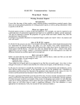
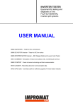
User Manual
Visualization Application for Industrial Robot
IRB-1400
Authors:
Aleksandra Felińska
Thijs van den Broek
Mateusz Kulikowski
Adam Ratajczak
Filip Sajdak
Project has been made by senior-year-student
from Control Engineering and Robotics, Wrocław Univ. of Technology in cooperation with
student from Department of Mechanical Engineering Dynamics and Control Technology, Eindhoven Univ. of Technology, Holland. This task
was accomplish within an university course named "Techniki komputerowe w robotyce"
Wrocław 2007
1
Overview
The main task of builded system id to show in 3-dimensional graphic a model of an industry
robot IRB-1400 which is standing in Robotics Laboratory 010/C-3.
System using a serial connection between robot and personal computer is collecting data from
internal robot sensors and putting them to computer application. Computer program, based on
received data, change the posture of 3-D robot model. Beside, the application can record model
change sequence and save this to file for later playing.
1.1
Compoments
Block diagram is presented in fig. 1. Measured data from sensors are sent through serial port to
PC application and are changed to movement of 3-D model.
Robot
Robot Controller
Personal Computer
Program
Program
Rysunek 1: Block diagram of visualization system
2
Preparation
To run the system:
• Connect robot serial port with serial port in PC using a null-modem cable,
• Start the vis application on PC,
• Prepare a program in robot controller (see description in point 3).
3
Program in robot controller
uchomić w sterowniku robota program o nazwie: simple3 (dopytaj Filipa o dyskietkę )
by uruchomić program
w sterowniku
robotain
należy:
To start
a program
robot controller (assume that program is on floppy disk):
akładamy, że program jest na dyskietce)
nacisnąć „Program key”
1. Press ”program key”
otworzyć okno.
to open window.
Wybrać z menu File->Open.
Zmienić Unit na dyskietkę
Wybrać program do wczytania.
ogram w sterowniku robota:
2
(zakładamy, że program jest na dyskietce)
1.nacisnąć „Program key”
by otworzyć okno.
2. Select
from
menu
2.Wybrać
z menu
File->Open.
File->Open.
3.Zmienić Unit na dyskietkę
4.Wybrać program do wczytania.
3. Change Unit to floppy disk.
Program w sterowniku robota:
4. Select program to be started.
// Declaration
VAR jointtarget joints;
// The current angles of the axes for the robot and external axes are stored in
joints.
joints:=CJointT();
// Open the serial channel for reading or writing .
Open "sio1:" , iodev\Bin;
// Writes a string to a binary serial channel. The string contains
// axis positions of the robot axes in degrees.
// Function ValToStr converts value to string.
WriteStrBin iodev1,ValToStr(joints.robax);
// Close the serial channel.
Close iodev1;
Because the multitasking in operation system in robot controller is not be done, the program
send sensors data in sequence order:
Open "sio1:" , iodev\Bin; //open port
joints:=CJointT();//read value from sensors
WriteStrBin iodev1,ValToStr(joints.robax); //sending data
(robot movement instruction, ex. MoveC, MoveL)
joints:=CJointT(); //read value from sensors
WriteStrBin iodev1,ValToStr(joints.robax); //sending data
...
(robot movement instruction, ex. MoveC, MoveL)
joints:=CJointT(); //read value from sensors
WriteStrBin iodev1,ValToStr(joints.robax); //sending data
Close iodev1;//close port
4
4.1
User manual of the vis application
vis overview
vis application was created to visualise industry robot IRB-1400 on PC screen. Application using
collected data change posture of the 3-D robot model. The change sequence can be record and
store in file on hard disk for future playing. Application also allow to simulate movement of the
real robot
4.2
User interface
Main window of the application has been showed on fig. 2. On the figure has been marked main
elements.
Main menu Description below in point 4.3.
Source selector Select the working mode, which data can change the model in 3-d view, more
detailed description in point 4.4.
Video To control recording and playing the movement sequence use this buttons.
3
Main menu
Source selector
Video
3-D view window
Joints
Communication
Rysunek 2: Main window of the Application
Joints To read actual position in joints click the "Get"button to set a position: enter value in
proper widget and click śet"button.
Communication All message about system work are displayed in this widget. In CommSimm mode a command line is appear. Whole list of proper command in appendix A.
4.3
Main menu
Connection In this submenu are connect/disconnect options to control the connection and
also there is setup option. In setup window is possibility to set the port configuration like
connection speed, parity etc. and change the application language.
View In this submenu is possible to select one from predefined view in 3-D window (front, top
etc). When the option Marker is set, the trace of the efector point is shown.
Toolbars Here is s possibility to turn on/off toolbars.
Help Pomoc do programu.
4.4
Working mode - Source selector
The application has three working modes:
• Robot - work with real robot,
• CommSim - manual change of the models position (command line or corresponding widgets),
• Video - mode to playing recorded sequence.
Tryb Robot Every correctly received data had changed posture of robot model in 3-D view.
Manual change of the position is not allowed, but there is a possibility to record the movement
sequence.
4
Tryb CommSim In this mode manual change the posture of the model is possible. To change
use correspondent widget or command line (all commands are in appendix A. Similar like the
previous mode here is also possibility to record a sequence.
Tryb Video Here is a possibility to play any recorded sequence. the continous play or frameby-frame mode is allowed.
5
Closing information
Full documentation of the program and library created for this project was delivered with source
codes to supervisor of the project.
A
Command list to use in command line
1. quit
2. set joint #nr #val
3. seta #1 ...#6
4. get joint #nr
5. info
6. reset
7. resetv
8. say
turn off the application
set joint #nr to value #val
set all joints to value #1 ...#6
return value of the angle in joint #nr
display information about vis
reset all values in joints
reset viewport
display message in window
5