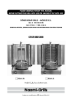
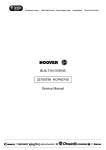
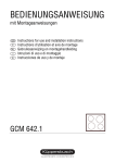
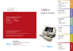
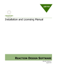
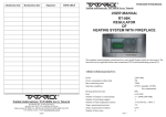
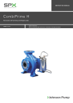
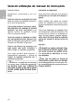
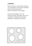
1
DÖNER KEBAP GRILLS – models EC.O. and EC.U.
elec t ric v ersion
INSTALLATION, operation AND maintenance instructions
read this manual carefully !!
before having this grill installed
before operating this grill
EC.O.3.E.
EC.O.4.E.
Model EC.O. has a top motor.
EC.U.3.E.
EC.U.4.E.
Model EC.U. has a bottom motor.
Naomi-Grills
Subject to modifications. © Naomi-Grills B.V.
2
TECHNICAL SPECIFICATIONS
Type
Number of electric elements
EC.O.3.E.
EC.O.4.E.
3
4
Mains
230 V / 400 V • 50 Hz • 3 ~ N/PE
Current
3 x 16 A
Power consumption
Heating surface w x h
Max. meat weight
Dimensions: w x d x h
incl. power regulators
Weight
Type
Number of electric elements
4.8 kW
6.4 kW
24 x 63 cm
24 x 80 cm
60 kg
80 kg
56.5 x 81.0 x 98.5 cm
56.5 x 81.0 x 115.0 cm
32 kg
35 kg
EC.U.3.E.
EC.U.4.E.
3
4
Mains
230 V / 400 V • 50 Hz • 3 ~ N/PE
Current
3 x 16 A
Power consumption
Heating surface w x h
Max. meat weight
Dimensions: w x d x h
incl. power regulators
Weight
Motor
4.8 kW
6.4 kW
24 x 63 cm
24 x 80 cm
60 kg
80 kg
56.5 x 66.5 x 98.5 cm
56.5 x 66.5 x 115.0 cm
40 kg
45 kg
230 V • 50 Hz • 3.5 W
1 Revolution per minute
Switch positions : 0 = off
I = clockwise
II = counter clockwise
3
TABLE OF CONTENTS
DRAWINGS/DESCRIPTIONS
Models EC.O.
Models EC.U.
Electrical diagrams
page 4, 5
page 6, 7
page 8
technical SPECIFICATIONS
page 2
GENERAL SAFETY REGULATIONS
page 9
1. SAFETY INSTRUCTIONS
1.1. Safety instructions concerning Installation
(Connecting and Locating)
1.2. Safety instructions for the User
page 10
2. CONNECTING
2.1. Connecting General
2.2. Heat shield (Models EC.O.)
2.3. Cord guide (Models EC.O.)
page 13
page 13
page 14
page 14
3. INITIAL USE page 14
4. USING THE electric elementS
page 15
5. PLACING THE SPIT
5.1 Models EC.O.
5.2 Models EC.U.
page 16
page 16
page 17
6. Replacing the motor
6.1 Models EC.O.
6.2 Models EC.U.
page 18
page 18
page 18
7. CLEANING
7.1. Cleaning General
7.2. Cleaning Robax® Ceramic Glass
page 18
page 18
page 18
8. MAINTENANCE page 19
9. guarantee page 19
page 10, 11
page 12
4
DRAWINGS/DESCRIPTIONS
Models EC.O. – top motor
1
2
3
4
22
21
20
5
6
7
19
8
back
18
9
23
16
17
10
11
16
13
12
14
1) upper guide column
2) heat shield with adjusting knob
3) motor in housing
4) motor switch
0 = off
l = clockwise
ll = counter clockwise
5) ring (for manual spit operation)
6) end stop
7) upper spit holder
8) adjusting knob motor/upper spit holder
9) spit
10) spit board
11) locking pin (for spit board)
15
2) bottom guide column
1
13) end stop
14) bottom spit holder with adjusting knob
15) dripping tray with perforated cover
16) power cord – electric elements
17) power regulator
18) heating surface (Robax® Color High
Trans Ceramic Glass)
19) power cord – motor
20) insert nut motor housing
21) cord guide
22) upper guide column hinge
23) socket
5
Model EC.U. – top motor
Placing the spit
3
6
1
8
7
9
22
10
11
12
13
14
6
DRAWINGS/DESCRIPTIONS
Models EC.U. – bottom motor
1
2
3
19
4
18
5
back
17
7
21
16
17
8
9
11
1) upper guide column
2) upper spit holder with adjusting knob
3) end stop
4) locking (for spit)
5) spit
6) power cord – motor
7) spit board
8) motor in housing
9) motor switch
0 = off
l = clockwise
ll = counter clockwise
10) dripping tray with outlet
11) dripping drawer
12) ball (spit drive mechanism)
10
13
14
15
3) bottom spit holder
1
14) A – locking pin for bottom spit holder
B – locking pin for spit board
15) guide rails for the housing of the
electric elements, with adjusting knob
16) power cord – electric elements
17) power regulator
18) housing of the electric elements
19) heating surface (Robax® Color High
Trans Ceramic Glass)
20) socket
21) bearing
22) fitting for motor
23) motor
6
7
Model EC.U. – bottom motor
Placing the spit
1
3
2
5
4
5
7
14
21
13
12
10
22
23
8
ELECTRICAL DIAGRAMS
EC.O.3.E. / EC.U.3.E.
Power
regulator
Energie1 1
regelaar
3 1 7 5
Power
regulator
Energie22
regelaar
3 1 7 5
Power
regulator
Energie3 3
regelaar
3 1 7 5
Socket
Stopcontact
Stopcont
L3 PE N
2
6
2
6
2
6
Stekker
Plug
Electric
element
Elektrisch
1 1
element
Electric
element
Elektrisch
2 2
element
R1
R2
230 V – 400 V / 1600
Electric
element
Elektrisch
33
element
R1
R2
230 V – 400 V / 1600
L3
R1
Motor
Motor
R2
N
M
~
230 V – 400 V / 1600
L1 L2 L3 N
PE
EC.O.4.E. / EC.U.4.E.
Power
Energieregulator
regelaar
1
1
3 1 7 5
Power
Energieregulator
regelaar
2 2
3 1 7 5
Power
Energieregulator
regelaar
3 3
3 1 7 5
Power
Energieregulator
regelaar
4 4
3 1 7 5
Socket
Stopcontact
Stopco
L3 PE N
2
6
2
6
2
6
2
6
Stekker
Plug
Electric
element
Elektrisch
2 2
element
Electric
element
Elektrisch
1 1
element
R1
R2
230 V – 400 V / 1600
R1
Electric
element
Elektrisch
44
element
Electric
element
Elektrisch
33
element
R2
230 V – 400 V / 1600
R1
R2
230 V – 400 V / 1600
R1
L3
R2
230 V – 400 V / 1600
Motor
Motor
N
M
~
L1 L2 L3 N
PE
9
GENERAL SAFETY REGULATIONS
IMPORTANT:
-
YOU HAVE TO STUDY THIS MANUAL CAREFULLY BEFORE HAVING
THIS DÖNER KEBAP GRILL CONNECTED AND BEFORE OPERATING
THIS GRILL OR ALLOWING IT TO BE OPERATED.
-
THIS GRILL IS TO BE CONNECTED, MAINTAINED OR REPAIRED BY
QUALIFIED PROFESSIONALS EXCLUSIVELY.
-
THE QUALIFIED INSTALLER TOO HAS TO STUDY THIS MANUAL
CAREFULLY BEFORE CONNECTING, MAINTAINING OR REPAIRING
THIS grill.
-
WHEN YOU LET OTHERS OPERATE THIS GRILL, THEY TOO HAVE TO
STUDY THIS MANUAL CAREFULLY BEFORE OPERATING THIS GRILL.
-
YOU NEED TO COMPLY WITH ALL NATIONAL, REGIONAL AND
LOCAL REQUIREMENTS AND REGULATIONS.
-
DAILY CLEANING, REGULAR MAINTENANCE AND PERIODIC
INSPECTION OF THIS DEVICE ARE ESSENTIAL.
10
1. SAFETY INSTRUCTIONS
1.1.Safety instructions concerning Installation (Connecting and
Locating)
- The power supply has to comply with all national, regional and local requirements
and regulations.
- The grill is for professional use and should only be connected by qualified
professionals, in accordance with all valid requirements and regulations.
- Before connecting, check if the device is suitable for the electricity present.
- The device has to be placed level and on a solid base.
- Make sure the space where the device is placed is appropriately ventilated.
- It is preferable to place the device directly under an extraction system.
This may be mandatory. Consult the appropriate authorities.
- In case the device is placed directly under an extraction system, this system has to
be sufficiently heat-proof and manufactured in non-flammable materials.
*The distances and temperature mentioned below are recommendations.
The guidelines applying in your case may differ from them. Consult the appropriate
authorities.
- In case the device is not placed directly under an extraction system, make sure there
is a free space above the device of at least 100 cm. If this is not possible, attend to
a heat-resistant isolation above the device with a minimum of 100 x 100 cm, to limit
the ceiling temperature to a maximum of 70 °C. The distance between the top of the
device and the ceiling has to be at least 50 cm in this case.
- The device can be placed apart from, in between or adjacent to other devices.
The available space left and right has to measure at least 20 cm. Keep a space of
at least 10 cm at the back of the device.
Keep space available at the front with a minimum of 100 cm, measured from the
heating surface (the ceramic glass).
- The device may under no circumstances be placed in the vicinity of flammable
walls, curtains, furnishings, decorations or other flammable materials. Therefore, the
device also may not be placed on flammable support (such as for example plastic
or wood; use for example stainless steel).
11
- The heat is intensive. Make sure that flammable materials are removed to a safe
distance from the device (around the device).
- Fire regulations must be scrupulously observed.
- Always take care of optimum fire prevention, the appropriate extinguishing materials
and of adequate knowledge of how to deal with fires.
- The appliance must be placed on a robust structure.
- If the appliance will be used in a closed area always use a hood for air ventilation.
min. 100 cm
min. 10 cm
min . 20 cm
min. 60 cm
max. 85 cm
12
1.2.Safety instructions for the User
- This grill is to be operated by competent persons only and only after careful reading
of this complete manual.
- The device may not be used for other purposes than it has been designed for.
- Take into account that the grill is very heavy and can become very hot during
operation.
- The device is not allowed to be moved during operation.
- Movement is only allowed in cooled condition.
- Never place objects on the grill, not even when it is switched off.
- During use the device has to be equipped with a dripping tray.
- Never leave a device in operation unattended.
- Prevent overheating of the power cord. Never use damaged cords.
- First disconnect the electrical connections with the device (remove the plugs from the
sockets) before cleaning the grill, in the event of defects or failures, for repairs and
in the event of accidents or calamities; if necessary de-activate the relevant fuses.
- Repairs and maintenance on the device are to be done by qualified professionals
exclusively.
Insertion and removal of the spit is only allowed when the device has cooled down.
Also be extremely careful when adjusting the spit position, moving the heat shield,
moving or emptying the dripping tray or dripping drawer, and when placing and
using the hand cross.
Protect yourself, wear heat resistant gloves.
Caution: after the electric elements have been switched off the Robax© ceramic
glass will remain very hot for some time.
13
2. CONNECTING
2.1. Connecting general
- Before connecting the device electrically, refer first to the specifications on the
type plate on the device, the technical specifications on page 2 and the electrical
diagram on page 8.
- Check whether a 400 V electricity supply is available for connecting with the
device. All electrical supplies to the device must be grounded.
- If the available electrical supplies are not suitable, contact an accredited installer
and/or your electricity supply company.
- The device must be connected by plug connection (and therefore not by permanent,
direct connection).
- Have connections and modifications only done by qualified professionals, including
the attachment of plugs.
Specification of electric elements
Number of electric elements
: EC.O.3.E. / EC.U.3.E. : 3
EC.O.4.E. / EC.U.4.E. : 4
Mains
: 230 V / 400 V • 50 Hz • 3 ~ N/PE
Power consumption
: EC.O.3.E. / EC.U.3.E. : 4.8 kW
(1.6 kW per element)
EC.O.4.E. / EC.U.4.E. : 6.4 kW
Current
: 3 x 16 A
Motor specifications
Mains
Power consumption
Revolutions Switch positions : 230 V – 50 Hz
: 3.5 W
: 1 Revolution per minute
: 0 = off, I = clockwise, II = counter-clockwise
Cables
- a grounded cable for the electrical elements (without plug, to be fitted) to be
connected to a grounded 400 V electrical socket
- Model EC.O.: a grounded silicon cable (with plug), suited for –40 to +180 °C, to
be connected to a grounded 230 V electrical socket
- Model EC.U.: a grounded cable (with plug) to be connected to a grounded 230 V
electrical socket
14
2.2. Heat shield (only for Models EC.O.)
The movable heat shield protects the motor better against overheating. Always take
care of placing the shield in an optimum position to ensure that the motor is as well
protected as possible at all times.
2.3. Cord guide (only for Models EC.O.)
The heat shield is fitted with a spiral. The electrical cable of the motor has to be fed
through this spiral to prevent that the cable comes nearby the burners. Make also sure
that the cable does not come into contact with other parts of the grill that may become
extremely hot.
3. INITIAL USE
Warning:
Make sure all the packing materials and foil are removed
before the electric elements are switched on for the first time.
Make sure that the Robax© ceramic glass is cleaned before
the electric elements are switched on for the first time; refer to
chapter 7.2.
15
4. USING THE ELECTRIC ELEMENTS
The grill is fitted with electric elements that are located directly behind the “Robax®
Color High Trans” Ceramic Glass.
Each element is separately regulated by its own power regulator.
4 positions are stipulated on the power regulator: 0, 1, 2 and 3.
Between the 0-position (off) and the 3-position (full) every desired position may be set
continuously.
By selecting the appropriate position the meat may be grilled quickly or slowly or kept
warm, taking into account:
- the kind of meat
- the thickness and height of the meat on the spit
- the position of the spit (vertical or horizontal)
- the distance of the meat from the Robax® ceramic glass (the electric elements)
One or more elements may be switched on.
After use all the elements must be switched off (0-position).
Caution: after the electric elements have been switched off, the Robax® ceramic
glass will remain very hot for some time.
16
5. PLACING THE SPIT
5.1.Placing the Spit
Model EC.O. (top spit drive mechanism)
Read the instructions below completely and carefully, before placing a spit with meat
in the grill for the first time!
Refer to the drawings on page 4 and 5.
- Place the dripping tray (15) under the bottom guide column (12).
- Slide the bottom spit holder (14) towards you, for the first time preferably to the end
stop (13) and fasten the adjusting knob (14).
- Slide the upper spit holder (7) towards you, for the first time preferably to the end
stop (6) and fasten the adjusting knob (8).
- Slide the heat shield (2) backwards and fasten the adjusting knob (2).
- Place the spit (9) with meat in the bottom spit holder (14).
- Lift the upper guide column (1).
Place the upper spit point (9) below the upper spit holder (7).
Lower the guide column (1), so that the upper spit holder (7) slides over the spit (9).
- Move the bottom spit holder (14) and/or the upper spit holder (7), to place the spit
with meat in the desired grill position: vertically or diagonally, closer to the heating
surface (18) (the Robax® ceramic glass) or further from the heating surface.
Attention: Always loosen one spit holder first, move it and fasten it again. Only turn
to the other spit holder after completion of the previous steps.
- Place the heat shield (2) in the desired position and fasten the adjusting knob (2).
- All actions mentioned above can be done with running or non-running motor (this
makes no difference at all).
17
5.2.Placing the Spit
Model EC.U. (bottom spit drive mechanism)
Read the instructions below completely and carefully, before placing a spit with meat
in the grill for the first time!
Refer to the drawings on pages 6 and 7.
- Put the motor in the off-position (10).
- Slide the housing of the electric elements (19) backwards as far as possible and
fasten the adjusting knob (16).
- Place the upper spit holder (2) at correct distance from the housing (19),
considering the thickness of the spit with meat and fasten the adjusting knob (2).
Open the locking (4) of this spit holder (2).
- Place the spit (5) with the bottom spit holder (14) on the ball (13).
Attention: Make sure the bottom spit holder (14) has already been fastened to the
spit (5) by means of the locking pin (15A), before placing the spit with meat in the
grill.
- Slide the upper spit point (5) in the upper spit holder (2) and lock it (4).
- Move the upper spit holder (2) to bring the spit with meat in the desired vertical or
diagonal position and fasten the adjusting knob (2).
- Move the housing (19) to place it at the required distance from the meat and fasten
the adjusting knob (16).
18
6. REPLACING THE MOTOR
6.1. Model EC.O. (top spit drive mechanism)
Delivery options for defect motor:
1) Complete set of motor in housing, switch, spit holder, power cord with plug,
or
2) Separate motor.
Replacement of the motor has to be done by a qualified professional.
Consult the dealer where the (new) device was bought.
6.2. Model EC.U. (bottom spit drive mechanism)
Replacement of the motor has to be done by a qualified professional.
Consult the dealer where the (new) device was bought.
7. CLEANING
7.1. Cleaning General
Before cleaning the grill, first disconnect the electrical connections with the device
(remove the plugs from the sockets) and wait until the grill has cooled down
completely.
Daily clean the entire grill very thoroughly after use.
Avoid corrosive, abrasive or other aggressive agents, using for example for the
stainless steel special grill cleaner.
Do not use hard, sharp or scratching objects.
Do not allow water or other fluids to penetrate the device.
Never use a water jet. The grill may not be immersed.
7.2. Cleaning the “Robax® Color High Trans” Ceramic Glass
Always use only soft, clean, lint-free cloths.
Never use for example abrasive sponges.
Always use only a specially developed cleaning agent for ceramic hob plates. The
manufacturer of your ceramic glass has tested and approved the following products:
Cera-fix, Ceraclen or Vitroclen. When used regularly, these approved products will
form an invisible protective coating on the ceramic glass, reducing the ability of food
remnants to stick to the surface and also making daily cleaning easier.
19
Never use chemical or aggressive agents, such as for example detergents, abrasives,
oven sprays, grill cleaners or spot removers.
These agents leave the ceramic glass unprotected and may cause permanent
damage, such as scratches, discolouration and dullness.
For persistent dirt a special scraper may be carefully used, for example Cera-quick.
You should always read carefully the relevant instructions before using a cleaning
agent.
Caution:
Prior to connecting the grill
Make sure that the ceramic glass has been cleaned before switching on the
electric elements for the first time:
- clean the ceramic glass with a damp cloth and rub it dry
- then apply a special cleaner to provide a protective coating.
After using the grill
After the electric elements have been switched off, the ceramic glass will
remain very hot for some time; wait until it has cooled down completely.
8. MAINTENANCE
It is essential to maintain the grill regularly considering hygiene, reliability in operation
and safety.
Depending on the frequency of use and the age of the device it should be checked
entirely at least every two years considering operation and safety.
Have maintenance exclusively done by qualified professionals.
9. GUARANTEE
This grill’s guarantee is completely taken over by the dealer where the new device was
bought. Without the original receipt of this purchase, all guarantee obligations expire.
All obligations also expire:
- if non-qualified professionals installed, maintained or repaired this grill,
- if any part of this grill has been replaced by non-original Naomi-Grills B.V. parts,
- if the grill is not operated professionally or used for purposes other than for which it
is intended,
- if any instruction from this manual has not been observed.
The guarantee conditions have to be supplied by the dealer in question.
Naomi-Grills
important
- NAOMI-GRILLS B.V. DISCLAIMS ANY LIABILITY FOR DAMAGE OR
BODILY INJURIES RESULTING FROM THE FAILURE TO OBSERVE
CAUTION OR CAREFULNESS, EVEN IF NOT DESCRIBED.
Subject to modifications.
© Naomi-Grills B.V.
Naomi-Grills B.V.
Anton Philipsweg 9 - 11 • 1422 AL Uithoorn • The Netherlands
Telephone +31 297 560 170 • Telefax +31 297 560 187
email: [email protected] • www.naomi-grills.com
11/2010
Naomi-Grills