1
RAPID reference manual
RAPID reference manual - part1a, Instructions A-R
Controller software IRC5
RobotWare 5.0
RAPID reference manual
3HAC 16581-1
Revision B
Controller software IRC5
RAPID reference manual - part 1a, Instructions A-R
Table of contents
RobotWare 5.0
Instructions A-R
Index
RAPID reference manual - part 1a, Instructions A-R
The information in this manual is subject to change without notice and should not be construed as a commitment by ABB. ABB
assumes no responsibility for any errors that may appear in this manual.
Except as may be expressly stated anywhere in this manual, nothing herein shall be construed as any kind of guarantee or
warranty by ABB for losses, damages to persons or property, fitness for a specific purpose or the like.
In no event shall ABB be liable for incidental or consequential damages arising from use of this manual and products described
herein.
This manual and parts thereof must not be reproduced or copied without ABB’s written permission, and contents thereof must
not be imparted to a third party nor be used for any unauthorized purpose. Contravention will be prosecuted.
Additional copies of this manual may be obtained from ABB at its then current charge.
©Copyright 2004 ABB All right reserved.
ABB Automation Technologies AB
Robotics
SE-721 68 Västerås
Sweden
RAPID reference manual - part 1a, Instructions A-R
Contents
AccSet - Reduces the acceleration ............................................................................................. 1
ActUnit - Activates a mechanical unit....................................................................................... 3
Add - Adds a numeric value....................................................................................................... 5
AliasIO - Define I/O signal with alias name.............................................................................. 7
“:=” - Assigns a value................................................................................................................ 11
BitClear - Clear a specified bit in a byte data ........................................................................ 13
BitSet - Set a specified bit in a byte data................................................................................. 15
BookErrNo - Book a RAPID system error number............................................................... 17
Break - Break program execution ........................................................................................... 19
CallByVar - Call a procedure by a variable............................................................................ 21
CancelLoad - Cancel loading of a module .............................................................................. 25
CirPathMode - Tool reorientation during circle path ........................................................... 27
Clear - Clears the value ............................................................................................................ 31
ClearIOBuff - Clear input buffer of a serial channel ............................................................ 33
ClearPath - Clear current path................................................................................................ 35
ClearRawBytes - Clear the contents of rawbytes data .......................................................... 37
ClkReset - Resets a clock used for timing ............................................................................... 39
ClkStart - Starts a clock used for timing................................................................................. 41
ClkStop - Stops a clock used for timing................................................................................... 43
Close - Closes a file or serial channel ...................................................................................... 45
CloseDir - Close a directory ..................................................................................................... 47
comment - Comment................................................................................................................. 49
Compact IF - If a condition is met, then... (one instruction) ................................................. 51
ConfJ - Controls the configuration during joint movement ................................................. 53
ConfL - Monitors the configuration during linear movement.............................................. 55
CONNECT - Connects an interrupt to a trap routine........................................................... 59
CopyFile - Copy a file ............................................................................................................... 61
CopyRawBytes - Copy the contents of rawbytes data ........................................................... 63
CorrClear - Removes all correction generators ..................................................................... 67
CorrCon - Connects to a correction generator....................................................................... 69
CorrDiscon - Disconnects from a correction generator......................................................... 75
CorrWrite - Writes to a correction generator ........................................................................ 77
DeactUnit - Deactivates a mechanical unit ............................................................................. 79
Decr - Decrements by 1............................................................................................................. 81
DitherAct - Enables dither for soft servo................................................................................ 83
DitherDeact - Disables dither for soft servo ........................................................................... 87
DropSensor - Drop object on sensor........................................................................................ 89
DropWObj - Drop work object on conveyor .......................................................................... 91
RAPID reference manual - part 1a, Instructions A-R
I
Contents
EOffsOff - Deactivates an offset for external axes ................................................................. 93
EOffsOn - Activates an offset for external axes ..................................................................... 95
EOffsSet - Activates an offset for external axes using a value .............................................. 97
EraseModule - Erase a module ................................................................................................ 99
ErrLog - Write an error message .......................................................................................... 101
ErrRaise - Writes a warning and calls an error handler .................................................... 105
ErrWrite - Write an error message ....................................................................................... 109
EXIT - Terminates program execution ..................................................................................111
ExitCycle - Break current cycle and start next .....................................................................113
FOR - Repeats a given number of times ................................................................................115
GetDataVal - Get the value of a data object ..........................................................................119
GetSysData - Get system data................................................................................................ 121
GetTrapData - Get interrupt data for current TRAP ......................................................... 123
GOTO - Goes to a new instruction ........................................................................................ 125
GripLoad - Defines the payload of the robot........................................................................ 127
HollowWristReset - Reset hollow wrist for IRB5402 and IRB5403 ................................... 129
IDelete - Cancels an interrupt................................................................................................ 131
IDisable - Disables interrupts ................................................................................................ 133
IEnable - Enables interrupts.................................................................................................. 135
IError - Orders an interrupt on errors................................................................................. 137
IF - If a condition is met, then ...; otherwise ... ..................................................................... 141
Incr - Increments by 1 ............................................................................................................ 143
IndAMove - Independent absolute position movement....................................................... 145
IndCMove - Independent continuous movement................................................................. 149
IndDMove - Independent delta position movement ............................................................ 153
IndReset - Independent reset ................................................................................................. 157
IndRMove - Independent relative position movement ........................................................ 161
InvertDO - Inverts the value of a digital output signal ....................................................... 167
IODisable - Disable I/O unit................................................................................................... 169
IOEnable - Enable I/O unit .................................................................................................... 173
IPers - Interrupt at value change of a persistent variable .................................................. 177
ISignalAI - Interrupts from analog input signal .................................................................. 179
ISignalAO - Interrupts from analog output signal .............................................................. 189
ISignalDI - Orders interrupts from a digital input signal................................................... 193
ISignalDO - Interrupts from a digital output signal............................................................ 197
ISignalGI - Orders interrupts from a group of digital input signals ................................. 201
ISignalGO - Orders interrupts from a group of digital output signals.............................. 205
ISleep - Deactivates an interrupt ........................................................................................... 209
II
RAPID reference manual - part 1a, Instructions A-R
Contents
IsPers - Is persistent ................................................................................................................ 211
ITimer - Orders a timed interrupt ........................................................................................ 213
IVarValue - orders a variable value interrupt ...................................................................... 217
IWatch - Activates an interrupt ............................................................................................. 221
label - Line name ..................................................................................................................... 223
Load - Load a program module during execution ............................................................... 225
LoadId - Load identification of tool or payload ................................................................... 229
MakeDir - Create a new directory......................................................................................... 235
ManLoadIdProc - Load identification of IRBP manipulators ........................................... 237
MechUnitLoad - Defines a payload for a mechanical unit.................................................. 241
MotionSup - Deactivates/Activates motion supervision ...................................................... 245
MoveAbsJ - Moves the robot to an absolute joint position ................................................. 249
MoveC - Moves the robot circularly...................................................................................... 255
MoveCDO - Moves the robot circularly and sets digital output in the corner.................. 261
MoveCSync - Moves the robot circularly and executes a RAPID procedure.................... 265
MoveExtJ - Move one or several mechanical units without TCP....................................... 269
MoveJ - Moves the robot by joint movement ....................................................................... 273
MoveJDO - Moves the robot by joint movement and sets digital output in the corner ... 277
MoveJSync - Moves the robot by joint movement and executes a RAPID procedure ..... 281
MoveL - Moves the robot linearly ......................................................................................... 285
MoveLDO - Moves the robot linearly and sets digital output in the corner ..................... 291
MoveLSync - Moves the robot linearly and executes a RAPID procedure ....................... 295
MToolRotCalib - Calibration of rotation for moving tool................................................... 299
MToolTCPCalib - Calibration of TCP for moving tool....................................................... 303
Open - Opens a file or serial channel .................................................................................... 307
OpenDir - Open a directory ................................................................................................... 311
PackDNHeader - Pack DeviceNet Header into rawbytes data ........................................... 313
PackRawBytes - Pack data into rawbytes data .................................................................... 317
PathAccLim - Reduce TCP acceleration along the path ..................................................... 323
PathRecMoveBwd - Move path recorder backwards.......................................................... 327
PathRecMoveFwd - Move path recorder forward............................................................... 331
PathRecStart - Start the path recorder ................................................................................. 335
PathRecStop - Stop the path recorder................................................................................... 339
PathResol - Override path resolution.................................................................................... 343
PDispOff - Deactivates program displacement .................................................................... 347
PDispOn - Activates program displacement......................................................................... 349
PDispSet - Activates program displacement using a value ................................................. 353
ProcerrRecovery - Generate and recover from process-move error.................................. 357
RAPID reference manual - part 1a, Instructions A-R
III
Contents
ProcCall - Calls a new procedure .......................................................................................... 363
PulseDO - Generates a pulse on a digital output signal ...................................................... 365
RAISE - Calls an error handler............................................................................................. 369
RaiseToUser - Propagates an error to user level.................................................................. 371
ReadAnyBin - Read data from a binary serial channel or file ........................................... 375
ReadBlock - read a block of data from device...................................................................... 379
ReadCfgData - Reads attribute of a system parameter....................................................... 381
ReadErrData - Gets information about an error................................................................. 383
ReadRawBytes - Read rawbytes data ................................................................................... 387
RemoveDir - Delete a directory ............................................................................................. 391
RemoveFile - Delete a file ....................................................................................................... 393
RenameFile - Rename a file ................................................................................................... 395
Reset - Resets a digital output signal..................................................................................... 397
RestoPath - Restores the path after an interrupt................................................................. 399
RETURN - Finishes execution of a routine .......................................................................... 401
Rewind - Rewind file position ................................................................................................ 403
RETRY - Resume execution after an error .......................................................................... 405
IV
RAPID reference manual - part 1a, Instructions A-R
AccSet
Instruction
RobotWare-OS
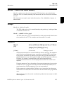
AccSet - Reduces the acceleration
AccSet is used when handling fragile loads. It allows slower acceleration and deceleration, which results in smoother robot movements.
This instruction can only be used in the Main task or, if in a MultiMove System, in
Motion tasks.
Examples
AccSet 50, 100;
The acceleration is limited to 50% of the normal value.
AccSet 100, 50;
The acceleration ramp is limited to 50% of the normal value.
Arguments
AccSet
Acc Ramp
Acc
Data type: num
Acceleration and deceleration as a percentage of the normal values. 100% corresponds to maximum acceleration. Maximum value: 100%.
Input value < 20% gives 20% of maximum acceleration.
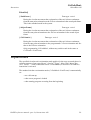
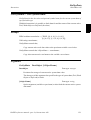
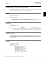
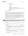
Ramp
Data type: num
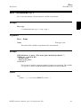
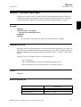
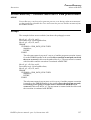
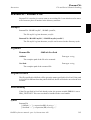
The rate at which acceleration and deceleration increases as a percentage of the
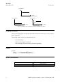
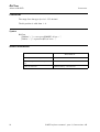
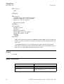
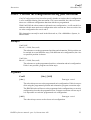
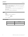
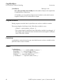
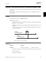
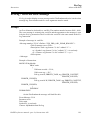
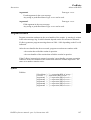
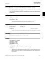
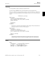
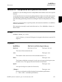
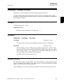
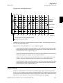
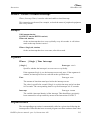
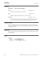
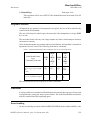
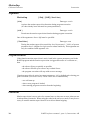
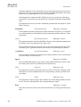
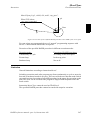
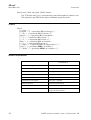
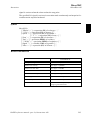
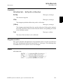
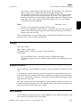
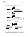
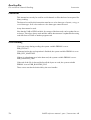
normal values (see Figure 1). Jerking can be restricted by reducing this value. 100% corresponds to maximum rate. Maximum value: 100%.
Input value < 10% gives 10% of maximum rate.
RAPID reference manual - part 1a, Instructions A-R
1
AccSet
RobotWare-OS
Instruction
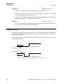
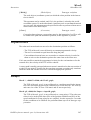
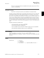
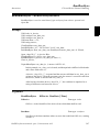
Acceleration
Time
AccSet 100, 100, i.e. normal acceleration
Acceleration
Acceleration
Time
Time
AccSet 30, 100
AccSet 100, 30
Figure 1 Reducing the acceleration results in smoother movements.
Program execution
The acceleration applies to both the robot and external axes until a new AccSet instruction is executed.
The default values (100%) are automatically set
- at a cold start-up
- when a new program is loaded
- when starting program executing from the beginning.
Syntax
AccSet
[ Acc ’:=’ ] < expression (IN) of num > ’,’ [ Ramp ’:=’ ] < expression (IN) of num > ’;’
Related information
Described in:
Positioning instructions
2
RAPID Summary - Motion
RAPID reference manual - part 1a, Instructions A-R
ActUnit
Instruction
RobotWare-OS
ActUnit - Activates a mechanical unit
ActUnit is used to activate a mechanical unit.
It can be used to determine which unit is to be active when, for example, common drive
units are used.
This instruction can only be used in the Main task or, if in a MultiMove System, in
Motion tasks.
Example
ActUnit orbit_a;
Activation of the orbit_a mechanical unit.
Arguments
ActUnit MechUnit
MechUnit
(Mechanical Unit)
Data type: mecunit
The name of the mechanical unit that is to be activated.
Program execution
When the robot and external axes have come to a standstill, the specified mechanical
unit is activated. This means that it is controlled and monitored by the robot.
If several mechanical units share a common drive unit, activation of one of these
mechanical units will also connect that unit to the common drive unit.
Limitations
Instruction ActUnit cannot be used in
- program sequence StorePath ... RestoPath
- event routine RESTART
RAPID reference manual - part 1a, Instructions A-R
3
ActUnit
RobotWare-OS
Instruction
Syntax
ActUnit
[MechUnit ’:=’ ] < variable (VAR) of mecunit> ’;’
Related information
Described in:
4
Deactivating mechanical units
Instructions - DeactUnit
Mechanical units
Data Types - mecunit
More examples
Instructions - DeactUnit
RAPID reference manual - part 1a, Instructions A-R
Add
Instruction
RobotWare-OS
Add - Adds a numeric value
Add is used to add or subtract a value to or from a numeric variable or persistent.
Examples
Add reg1, 3;
3 is added to reg1, i.e. reg1:=reg1+3.
Add reg1, -reg2;
The value of reg2 is subtracted from reg1, i.e. reg1:=reg1-reg2.
Arguments
Add
Name AddValue
Name
Data type: num
The name of the variable or persistent to be changed.
AddValue
Data type: num
The value to be added.
Syntax
Add [ Name ’:=’ ] < var or pers (INOUT) of num > ’,’
[ AddValue ’:=’ ] < expression (IN) of num > ’;’
RAPID reference manual - part 1a, Instructions A-R
5
Add
RobotWare-OS
Instruction
Related information
Described in:
6
Incrementing a variable by 1
Instructions - Incr
Decrementing a variable by 1
Instructions - Decr
Changing data using an arbitrary
Instructions - :=expression, e.g. multiplication
RAPID reference manual - part 1a, Instructions A-R
AliasIO
Instruction
Advanced RAPID
AliasIO - Define I/O signal with alias name
AliasIO is used to define a signal of any type with an alias name or to use signals in
built-in task modules.
Signals with alias names can be used for predefined generic programs, without any
modification of the program before running in different robot installations.
The instruction AliasIO must be run before any use of the actual signal. See example 1
below for loaded modules and example 2 below for builtin modules.
Example 1
VAR signaldo alias_do;
PROC prog_start()
AliasIO config_do, alias_do;
ENDPROC
The routine prog_start is connected to the START event in system parameters.
The program defined digital output signal alias_do is connected to the configured digital output signal config_do at program start (start the program from
beginning).
Arguments
AliasIO
FromSignal ToSignal
FromSignal
Data type: signalxx or string
Loaded modules:
The signal identifier named according to the configuration (data type signalxx)
from which the signal descriptor is copied. The signal must be defined in the IO
configuration.
Built-in modules:
A reference (CONST, VAR, PERS or parameter of these) containing the name of
the signal (data type string) from which the signal descriptor after search in the
system is copied. The signal must be defined in the IO configuration.
RAPID reference manual - part 1a, Instructions A-R
7
AliasIO
Advanced RAPID
Instruction
ToSignal
Data type: signalxx
The signal identifier according to the program (data type signalxx) to which the
signal descriptor is copied. The signal must be declared in the RAPID program.
The same data type must be used (or find) for the arguments FromSignal and ToSignal
and must be one of type signalxx (signalai, signalao, signaldi, signaldo, signalgi or signalgo).
Program execution
The signal descriptor value is copied from the signal given in argument FromSignal to
the signal given in argument ToSignal.
Example 2
VAR signaldi alias_di;
PROC prog_start()
CONST string config_string := "config_di";
AliasIO config_string, alias_di;
ENDPROC
The routine prog_start is connected to the START event in system parameters.
The program defined digital output signal alias_di is connected to the configured
digital output signal config_di (via constant config_string) at program start (start
the program from the beginning).
Limitation
When starting the program, the alias signal cannot be used until the AliasIO instruction
is executed.
Instruction AliasIO must be placed
- either in the event routine executed at program start (event START)
- or in the program part executed after every program start (before use of the signal)
In order to prevent mistakes it is not recomended to use dynamic reconnection of an
AliasIO signal to different physical signals.
8
RAPID reference manual - part 1a, Instructions A-R
AliasIO
Instruction
Advanced RAPID
Syntax
AliasIO
[ FromSignal ’:=’ ] < reference (REF) of anytype> ’,’
[ ToSignal ’:=’ ] < variable (VAR) of anytype> ’;’
Related information
Described in:
Input/Output instructions
RAPID Summary - Input and Output Signals
Input/Output functionality in general
Motion and I/O Principles - I/O Principles
Configuration of I/O
System Parameters
Defining event routines
System Parameters
Loaded/Built-in task modules
System Parameters
RAPID reference manual - part 1a, Instructions A-R
9
AliasIO
Advanced RAPID
10
Instruction
RAPID reference manual - part 1a, Instructions A-R
“:=”
Instruction
RobotWare-OS
“:=” - Assigns a value
The “:=” instruction is used to assign a new value to data. This value can be anything
from a constant value to an arithmetic expression, e.g. reg1+5*reg3.
Examples
reg1 := 5;
reg1 is assigned the value 5.
reg1 := reg2 - reg3;
reg1 is assigned the value that the reg2-reg3 calculation returns.
counter := counter + 1;
counter is incremented by one.
Arguments
Data := Value
Data
Data type: All
The data that is to be assigned a new value.
Value
Data type: Same as Data
The desired value.
Examples
tool1.tframe.trans.x := tool1.tframe.trans.x + 20;
The TCP for tool1 is shifted 20 mm in the X-direction.
pallet{5,8} := Abs(value);
An element in the pallet matrix is assigned a value equal to the absolute value of
the value variable.
RAPID reference manual - part 1a, Instructions A-R
11
“:=”
RobotWare-OS
Instruction
Limitations
The data (whose value is to be changed) must not be
- a constant
- a non-value data type.
The data and value must have similar (the same or alias) data types.
Syntax
(EBNF)
<assignment target> ’:=’ <expression> ’;’
<assignment target> ::= <variable>
| <persistent>
| <parameter>
| <VAR>
Related information
Described in:
12
Expressions
Basic Characteristics - Expressions
Non-value data types
Basic Characteristics - Data Types
Assigning an initial value to data
Basic Characteristics - Data Programming and
Testing
Manually assigning a value to data
Programming and Testing
RAPID reference manual - part 1a, Instructions A-R
BitClear
Instruction
Advanced RAPID
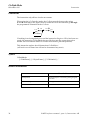
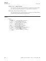
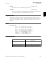
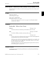
BitClear - Clear a specified bit in a byte data
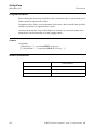
BitClear is used to clear (set to 0) a specified bit in a defined byte data.
Examples
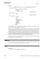
CONST num parity_bit := 8;
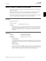
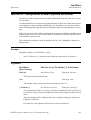
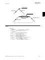
VAR byte data1 := 130;
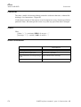
BitClear data1, parity_bit;
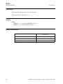
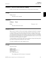
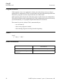
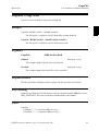
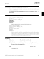
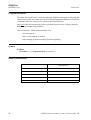
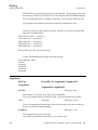
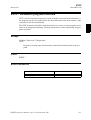
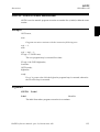
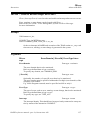
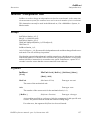
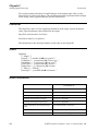
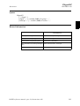
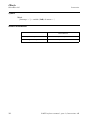
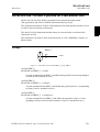
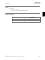
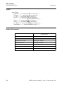
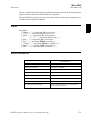
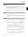
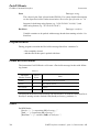
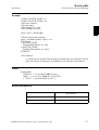
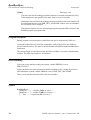
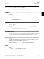
1 0 0 0 0 0 1 0
BitPos 1
BitPos 8
BitPos 1
BitPos 8
Bit number 8 (parity_bit) in the variable data1 will be set to 0, e.g. the content
of the variable data1 will be changed from 130 to 2 (decimal representation).
0 0 0 0 0 0 1 0
Bit position 8 has value 1.
Bit position 8 is set to 0.
VAR byte data1 := 130;
Content of data1 before BitClear ... : 130
BitClear data1, parity_bit;
Content of data1 after BitClear ... : 2
Figure 2 Bit manipulation of data type byte when using BitClear
Arguments
BitClear
BitData BitPos
BitData
Data type: byte
The bit data, in decimal representation, to be changed.
BitPos
(Bit Position)
Data type: num
The bit position (1-8) in the BitData to be set to 0.
RAPID reference manual - part 1a, Instructions A-R
13
BitClear
Advanced RAPID
Instruction
Limitations
The range for a data type byte is 0 - 255 decimal.
The bit position is valid from 1 - 8.
Syntax
BitClear
[ BitData’:=’ ] < var or pers (INOUT) of byte > ’,’
[ BitPos’:=’ ] < expression (IN) of num > ’;’
Related information
Described in:
14
Set a specified bit in a byte data
Instructions - BitSet
Check if a specified bit in a byte data is
set
Functions - BitCheck
Other bit functions
RAPID Summary - Bit Functions
RAPID reference manual - part 1a, Instructions A-R
BitSet
Instruction
Advanced RAPID
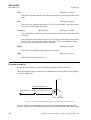
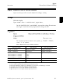
BitSet - Set a specified bit in a byte data
BitSet is used to set a specified bit to 1 in a defined byte data.
Examples
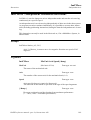
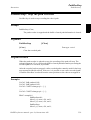
CONST num parity_bit := 8;
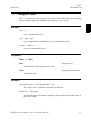
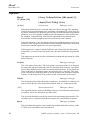
VAR byte data1 := 2;
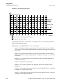
BitSet data1, parity_bit;
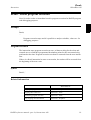
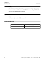
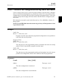
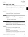
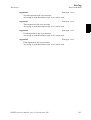
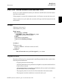
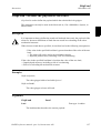
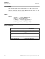
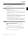
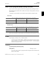
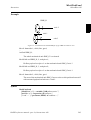
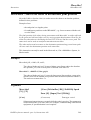
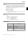
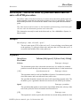
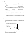
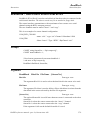
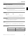
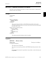
0 0 0 0 0 0 1 0
BitPos 1
BitPos 8
BitPos 1
BitPos 8
Bit number 8 (parity_bit) in the variable data1 will be set to 1, e.g. the content
of the variable data1 will be changed from 2 to 130 (decimal representation).
1 0 0 0 0 0 1 0
Bit position 8 has value 0.
Bit position 8 is set to 1.
VAR byte data1 := 2;
Content of data1 before BitSet ... : 2
BitSet data1, parity_bit;
Content of data1 after BitSet ... : 130
Figure 3 Bit manipulation of data type byte when using BitSet
Arguments
BitSet
BitData BitPos
BitData
Data type: byte
The bit data, in decimal representation, to be changed.
BitPos
(Bit Position)
Data type: num
The bit position (1-8) in the BitData to be set to 1.
RAPID reference manual - part 1a, Instructions A-R
15
BitSet
Advanced RAPID
Instruction
Limitations
The range for a data type byte is 0 - 255 decimal.
The bit position is valid from 1 - 8.
Syntax
BitSet
[ BitData’:=’ ] < var or pers (INOUT) of byte > ’,’
[ BitPos’:=’ ] < expression (IN) of num > ’;’
Related information
Described in:
16
Clear a specified bit in a byte data
Instructions - BitClear
Check if a specified bit in a byte data is set
Functions - BitCheck
Other bit functions
RAPID Summary - Bit Functions
RAPID reference manual - part 1a, Instructions A-R
BookErrNo
Instruction
Advanced RAPID
BookErrNo - Book a RAPID system error number
BookErrNo is used to book a new RAPID system error number.
Examples
! Introduce a new error number in a glue system
! Note: The new error variable must be declared with the initial value -1
VAR errnum ERR_GLUEFLOW := -1;
! Book the new RAPID system error number
BookErrNo ERR_GLUEFLOW;
The variable ERR_GLUEFLOW will be assigned to a free system error number
for use in the RAPID code.
! Use the new error number IF di1 = 0 THEN
RAISE ERR_GLUEFLOW;
ELSE
...
ENDIF
! Error handling
ERROR
IF ERRNO = ERR_GLUEFLOW THEN
...
ELSE
...
ENDIF
If the digital input di1 is 0 the new booked error number will be raised and the
system error number ERRNO will be set to the new booked error number. The
error handling of those user generated errors can then be handled in the error handler as usual.
Arguments
BookErrNo
ErrorName
ErrorName
Data type: errnum
The new RAPID system error variable name.
RAPID reference manual - part 1a, Instructions A-R
17
BookErrNo
Advanced RAPID
Instruction
Limitations
The new error variable must not be declared as a routine variable.
The new error variable must be declared with an initial value of -1, that gives the information that this error should be a RAPID system error.
Syntax
BookErrNo
[ ErrorName’:=’ ] < variable (VAR) of errnum > ’;’
Related information
Described in:
18
Error handling
Basic Characteristics -Error Recovery
Error number
Data types - errnum
Call an error handler
Instructions - RAISE
RAPID reference manual - part 1a, Instructions A-R
Break
Instruction
RobotWare-OS
Break - Break program execution
Break is used to make an immediate break in program execution for RAPID program
code debugging purposes.
Example
..
Break;
...
Program execution stops and it is possible to analyse variables, values etc. for
debugging purposes.
Program execution
The instruction stops program execution at once, without waiting for the robot and
external axes to reach their programmed destination points for the movement being
performed at the time. Program execution can then be restarted from the next instruction.
If there is a Break instruction in some event routine, the routine will be executed from
the beginning of the next event.
Syntax
Break’;’
Related information
Described in:
Stopping for program actions
Instructions - Stop
Stopping after a fatal error
Instructions - EXIT
Terminating program execution
Instructions - EXIT
Only stopping robot movements
Instructions - StopMove
RAPID reference manual - part 1a, Instructions A-R
19
Break
RobotWare-OS
20
Instruction
RAPID reference manual - part 1a, Instructions A-R
CallByVar
Instruction
RobotWare-OS
CallByVar - Call a procedure by a variable
CallByVar (Call By Variable) can be used to call procedures with specific names, e.g.
proc_name1, proc_name2, proc_name3 ... proc_namex via a variable.
Example
reg1 := 2;
CallByVar “proc”, reg1;
The procedure proc2 is called.
Arguments
CallByVar Name Number
Name
Data type: string
The first part of the procedure name, e.g. proc_name.
Number
Data type: num
The numeric value for the number of the procedure. This value will be converted
to a string and gives the 2:nd part of the procedure name e.g. 1. The value must
be a positive integer.
Example
Static selection of procedure call
TEST reg1
CASE 1:
lf_door door_loc;
CASE 2:
rf_door door_loc;
CASE 3:
lr_door door_loc;
CASE 4:
rr_door door_loc;
DEFAULT:
EXIT;
ENDTEST
Depending on whether the value of register reg1 is 1, 2, 3 or 4, different procedures are called that perform the appropriate type of work for the selected door.
The door location in argument door_loc.
RAPID reference manual - part 1a, Instructions A-R
21
CallByVar
RobotWare-OS
Instruction
Dynamic selection of procedure call with RAPID syntax
reg1 := 2;
%”proc”+NumToStr(reg1,0)% door_loc;
The procedure proc2 is called with argument door_loc.
Limitation: All procedures must have a specific name e.g. proc1, proc2, proc3.
Dynamic selection of procedure call with CallByVar
reg1 := 2;
CallByVar “proc”,reg1;
The procedure proc2 is called.
Limitation: All procedures must have specific name, e.g. proc1, proc2, proc3,
and no arguments can be used.
Limitations
Can only be used to call procedures without parameters.
Can not be used to call LOCAL procedures.
Execution of CallByVar takes a little more time than execution of a normal procedure
call.
Error handling
In the event of a reference to an unknown procedure, the system variable ERRNO is set
to ERR_REFUNKPRC.
In the event of the procedure call error (not procedure), the system variable ERRNO is
set to ERR_CALLPROC.
These errors can be handled in the error handler.
Syntax
CallByVar
[Name ‘:=’] <expression (IN) of string>’,’
[Number ‘:=‘] <expression (IN) of num>’;’
22
RAPID reference manual - part 1a, Instructions A-R
CallByVar
Instruction
RobotWare-OS
Related information
Described in:
Calling procedures
RAPID reference manual - part 1a, Instructions A-R
Basic Characteristic - Routines, Operator’s manual - IRC5 with FlexPendant
23
CallByVar
RobotWare-OS
24
Instruction
RAPID reference manual - part 1a, Instructions A-R
CancelLoad
Instruction
RobotWare-OS
CancelLoad - Cancel loading of a module
CancelLoad is used to cancel the loading of a module that is being or has been loaded
with the instruction StartLoad.
CancelLoad can be used only between the instruction
Startload ... WaitLoad.
Example
CancelLoad load1;
The load session load1 is cancelled.
Arguments
CancelLoad
LoadNo
LoadNo
Data type: loadsession
Reference to the load session, fetched by the instruction StartLoad.
Examples
VAR loadsession load1;
StartLoad “HOME:”\File:=”PART_B.MOD”,load1;
...
IF .................
CancelLoad load1;
StartLoad “HOME:”\File:=”PART_C.MOD”,load1;
ENDIF
...
WaitLoad load1;
The instruction CancelLoad will cancel the on-going loading of the module
PART_B.MOD and make it possible to in stead load PART_C.MOD.
Error handling
If the variable specified in argument LoadNo is not in use, meaning that no load session
is in use, the system variable ERRNO is set to ERR_LOADNO_NOUSE. This error
can then be handled in the error handler.
RAPID reference manual - part 1a, Instructions A-R
25
CancelLoad
RobotWare-OS
Instruction
Syntax
CancelLoad
[ LoadNo ’:=’ ] < variable (VAR) of loadsession > ’;’
Related information
Described in:
26
Load a program module during
execution
Instructions - StartLoad
Connect the loaded module to
the task
Instructions - WaitLoad
Load session
Data Types - loadsession
Load a program module
Instructions - Load
Unload a program module
Instructions - UnLoad
Accept unsolved references
System Parameters - Controller/Task/ BindRef
RAPID reference manual - part 1a, Instructions A-R
CirPathMode
Instruction
RobotWare-OS
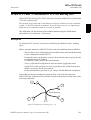
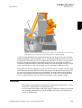
CirPathMode - Tool reorientation during circle path
CirPathMode (Circle Path Mode) makes it possible to select different modes to reorientate the tool during circular movements.
This instruction can only be used in the Main task or, if in a MultiMove System, in
Motion tasks.
Example
CirPathMode \PathFrame;
Standard mode for tool reorientation in the actual path frame from the start point
to the ToPoint during all succeeding circular movements.
This is default in the system.
CirPathMode \ObjectFrame;
Modified mode for tool reorientation in actual object frame from the start point
to the ToPoint during all succeeding circular movements.
CirPathMode \CirPointOri;
Modified mode for tool reorientation from the start point via the programmed
CirPoint orientation to the ToPoint during all succeeding circular movements.
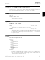
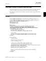
Description
PathFrame
The picture shows the tool reorientation for the standard mode \PathFrame.
The arrows shows the tool from wrist
centre point to tool centre point for the
programmed points.
The path for the wrist centre point is dotted in the figure.
The \PathFrame mode make it easy to
get the same angle of the tool around the
cylinder. The robot wrist will not go
through the programmed orientation in
the CirPoint.
RAPID reference manual - part 1a, Instructions A-R
27
CirPathMode
RobotWare-OS
Instruction
Use of standard mode \PathFrame with fixed tool orientation:
This picture shows the obtained orientation of the tool in the middle of the circle
using a leaning tool and \PathFrame
mode.
Compare with the figure below when \ObjectFrame mode is used
ObjectFrame
Use of modified mode \ObjectFrame with fixed tool orientation:
This picture shows the obtained orientation of the tool in the middle of the circle
using a leaning tool and \ObjectFrame
mode.
This mode will make a linear reorientation
of the tool in the same way as for MoveL.
The robot wrist will not go through the
programmed orientation in the CirPoint.
Compare with the figure above when \PathFrame mode is used
CirPointOri
The picture shows the different tool reorientation between the standard mode \PathFrame and the modified mode \CirPointOri.
\Pathframe
\CirPointOri
The arrows shows the tool from wrist centre point to tool centre point for the programmed points.
The different paths for the wrist centre
point are dotted in the figure.
The \CirPointOri mode will make the
robot wrist to go through the programmed
orientation in the CirPoint.
Arguments
CirPathMode
28
[\PathFrame] | [\ObjectFrame] | [\CirRAPID reference manual - part 1a, Instructions A-R
CirPathMode
Instruction
RobotWare-OS
PointOri]
[ \PathFrame ]
Data type: switch
During the circular movement the reorientaion of the tool is done continuous
from the start point orientation to the ToPoint orientation in the actual path frame.
This is the standard mode in the system.
[ \ObjectFrame ]
Data type: switch
During the circular movement the reorientaion of the tool is done continuous
from the start point orientation to the ToPoint orientation in the actual object
frame.
[ \CirPointOri ]
Data type: switch
During the circular movement the reorientaion of the tool is done continuous
from the start point orientation to the programmed CirPoint orientation and further to the ToPoint orientation.
Only programming CirPathMode; without any switch result in the same as CirPointOri \PathFrame;
Program execution
The specified circular tool reorientation mode applies for the next executed robot circular movements of any type (MoveC, SearchC, TriggC, MoveCDO, MoveCSync,
ArcC, PaintC ... ) and is valid until a new CirPathMode (or obsolete CirPathReori)
instruction is executed.
The standard circular reorientation mode (CirPathMode \PathFrame) is automatically
set
- at a cold start-up
- when a new program is loaded
- when starting program executing from the beginning.
RAPID reference manual - part 1a, Instructions A-R
29
CirPathMode
RobotWare-OS
Instruction
Limitations
The instruction only affects circular movements.
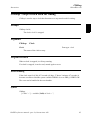
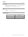
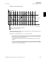
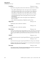
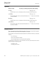
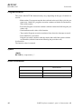
When using the \CirPointOri mode, the CirPoint must be between the points
A and B according to the figure below to make the circle movement to go through
the programmed orientation in the CirPoint.
1 /4
A 1 /4
1 /4
B
1 /4
CirPoint
If working in wrist singularity area and the instruction SingArea \Wrist has been executed, the instruction CirPathMode has no effect because the system then select
another tool reorientation mode for circular movements (joint interpolation).
This instruction replace the old instruction CirPathReori
(will work even in future but will not be documented any more).
Syntax
CirPathMode
[‘\’PathFrame] | [‘\’ObjectFrame] | [‘\’CirPointOri] ‘;’
Related information
Described in:
30
Interpolation
Motion Principles - Positioning during Program
Execution
Motion settings data
Data Types - motsetdata
Circular move instruction
Instructions - MoveC
RAPID reference manual - part 1a, Instructions A-R
Clear
Instruction
RobotWare-OS
Clear - Clears the value
Clear is used to clear a numeric variable or persistent , i.e. it sets it to 0.
Example
Clear reg1;
Reg1 is cleared, i.e. reg1:=0.
Arguments
Clear
Name
Name
Data type: num
The name of the variable or persistent to be cleared.
Syntax
Clear
[ Name ’:=’ ] < var or pers (INOUT) of num > ’;’
Related information
Described in:
Incrementing a variable by 1
Instructions - Incr
Decrementing a variable by 1
Instructions - Decr
RAPID reference manual - part 1a, Instructions A-R
31
Clear
RobotWare-OS
32
Instruction
RAPID reference manual - part 1a, Instructions A-R
ClearIOBuff
Instruction
File and Serial Channel Handling
ClearIOBuff - Clear input buffer of a serial channel
ClearIOBuff (Clear I/O Buffer) is used to clear the input buffer of a serial channel. All
buffered characters from the input serial channel are discarded.
Example
VAR iodev channel2;
...
Open "com2:", channel2 \Bin;
ClearIOBuff channel2;
WaitTime 0.1;
The input buffer for the serial channel referred to by channel2 is cleared. The
waittime guarantees the clear operation enough time to finish.
Arguments
ClearIOBuff
IODevice
IODevice
Data type: iodev
The name (reference) of the serial channel whose input buffer is to be cleared.
Program execution
All buffered characters from the input serial channel are discarded. Next read instructions will wait for new input from the channel.
Limitations
This instruction can only be used for serial channels. No wait for acknowledge of the operation is done. A waittime 0.1 after the instruction
is recommended to give the operation enough time in every application.
Error handling
If trying to use the instruction on a file, the system variable ERRNO is set to
ERR_FILEACC. This error can then be handled in the error handler.
RAPID reference manual - part 1a, Instructions A-R
33
ClearIOBuff
File and Serial Channel Handling
Instruction
Syntax
ClearIOBuff
[IODevice ’:=’] <variable (VAR) of iodev>’;’
Related information
Described in:
Opening a serial channel
34
RAPID Summary - Communication
RAPID reference manual - part 1a, Instructions A-R
ClearPath
Instruction
RobotWare-OS
ClearPath - Clear current path
ClearPath (Clear Path) clear the whole motion path on the current motion path level
(base level or StorePath level).
With motion path means all the movement segments from any move instructions which
has been executed in RAPID but not performed by the robot at the execution time of ClearPath.
The robot must be in a stop point position or must be stopped by StopMove before the
instruction ClearPath can be executed.
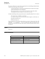
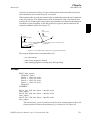
Example
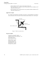
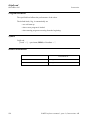
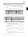
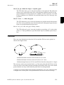
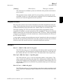
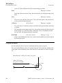
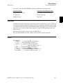
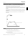
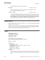
Start point home
MoveL p1, v500, fine, gripper;
End point p1
px
The robot drops its payload here and
execution continues in the trap
routine
In the following program example, the robot moves from the position home to the position p1. At the point px the signal di1 will indicate that the payload has been dropped.
The execution continues in the trap routine gohome. The robot will stop moving (start
the braking) at px, the path will be cleared, the robot will move to position home. The
error will be raised up to the calling routine minicycle and the whole user defined program cycle proc1 .. proc2 will be executed from beginning one more time.
VAR intnum drop_payload;
CONST errnum ERR_DROP_LOAD := 1;
PROC minicycle()
..........
proc1;
..........
ERROR (ERR_DROP_LOAD)
RETRY;
ENDPROC
RAPID reference manual - part 1a, Instructions A-R
35
ClearPath
RobotWare-OS
Instruction
PROC proc1()
..........
proc2;
..........
ENDPROC
PROC proc2()
CONNECT drop_payload WITH gohome;
ISignalDI \Single, di1, 1, drop_payload;
MoveL p1, v500, fine, gripper;
...........
IDelete drop_payload
ENDPROC
TRAP gohome
StopMove \Quick;
ClearPath;
IDelete drop_payload;
MoveL home, v500, fine, gripper;
RAISE ERR_DROP_LOAD;
ERROR
RAISE;
ENDTRAP
If the same program is being run but without StopMove and ClearPath in the trap
routine gohome, the robot will continue to position p1 before going back to position home.
If programming MoveL home with flying-point (zone) instead of stop-point
(fine), the movement is going on during the RAISE to the error handler in procedure minicycle and further until the movement is ready.
Syntax
ClearPath ’;’
Related information
Described in:
36
Stop robot movements
Instructions - StopMove
Error recovery
RAPID Summary - Error Recovery Basic Characteristics - Error Recovery
RAPID reference manual - part 1a, Instructions A-R
ClearRawBytes
Instruction
File and Serial Channel Handling
ClearRawBytes - Clear the contents of rawbytes data
ClearRawBytes is used to set all the contents of a rawbytes variable to 0.
Example
VAR rawbytes raw_data;
VAR num integer := 8
VAR num float := 13.4;
PackRawBytes integer, raw_data, 1 \IntX := DINT;
PackRawBytes float, raw_data, (RawBytesLen(raw_data)+1) \Float4;
ClearRawBytes raw_data \FromIndex := 5;
In the first 4 bytes the value of integer is placed (from index 1) and in the next 4
bytes starting from index 5 the value of float.
The last instruction in the example clears the contents of raw_data, starting at
index 5, i.e. float will be cleared, but integer is kept in raw_data.
Current length of valid bytes in raw_data is set to 4.
Arguments
ClearRawBytes
RawData [ \FromIndex ]
RawData
Data type: rawbytes
RawData is the data container which will be cleared.
[ \FromIndex ]
Data type: num
With \FromIndex it is specified, where to start clearing the contents of RawData.
Everything is cleared to the end.
If \FromIndex is not specified, all data starting at index 1 is cleared.
Program execution
Data from index 1 (default) or from \FromIndex in the specified variable is reset to 0.
The current length of valid bytes in the specified variable is set to 0 (default) or to (FromIndex - 1) if \FromIndex is programmed.
RAPID reference manual - part 1a, Instructions A-R
37
ClearRawBytes
File and Serial Channel Handling
Instruction
Syntax
ClearRawBytes [RawData ’:=’ ] < variable (VAR) of rawbytes>
[‘\’FromIndex ‘:=’ <expression (IN) of num>]‘;’
Related information
Described in:
38
rawbytes data
Data Types - rawbytes
Get the length of rawbytes data
Functions - RawBytesLen
Copy the contents of rawbytes data
Instructions - CopyRawBytes
Pack DeviceNet header into rawbytes data
Instructions - PackDNHeader
Pack data into rawbytes data
Instructions - PackRawBytes
Write rawbytes data
Instructions - WriteRawBytes
Read rawbytes data
Instructions - ReadRawBytes
Unpack data from rawbytes data
Instructions - UnpackRawBytes
RAPID reference manual - part 1a, Instructions A-R
ClkReset
Instruction
RobotWare-OS
ClkReset - Resets a clock used for timing
ClkReset is used to reset a clock that functions as a stop-watch used for timing.
This instruction can be used before using a clock to make sure that it is set to 0.
Example
ClkReset clock1;
The clock clock1 is reset.
Arguments
ClkReset
Clock
Clock
Data type: clock
The name of the clock to reset.
Program execution
When a clock is reset, it is set to 0.
If a clock is running, it will be stopped and then reset.
Syntax
ClkReset [ Clock ’:=’ ] < variable (VAR) of clock > ’;’
Related Information
Described in:
Other clock instructions
RAPID reference manual - part 1a, Instructions A-R
RAPID Summary - System & Time
39
ClkReset
RobotWare-OS
40
Instruction
RAPID reference manual - part 1a, Instructions A-R
ClkStart
Instruction
RobotWare-OS
ClkStart - Starts a clock used for timing
ClkStart is used to start a clock that functions as a stop-watch used for timing.
Example
ClkStart clock1;
The clock clock1 is started.
Arguments
ClkStart
Clock
Clock
Data type: clock
The name of the clock to start.
Program execution
When a clock is started, it will run and continue counting seconds until it is stopped.
A clock continues to run when the program that started it is stopped. However, the
event that you intended to time may no longer be valid. For example, if the program
was measuring the waiting time for an input, the input may have been received while
the program was stopped. In this case, the program will not be able to “see” the event
that occurred while the program was stopped.
A clock continues to run when the robot is powered down as long as the battery backup retains the program that contains the clock variable.
If a clock is running it can be read, stopped or reset.
Example
VAR clock clock2;
ClkReset clock2;
ClkStart clock2;
WaitUntil DInput(di1) = 1;
ClkStop clock2;
time:=ClkRead(clock2);
The waiting time for di1 to become 1 is measured.
RAPID reference manual - part 1a, Instructions A-R
41
ClkStart
RobotWare-OS
Instruction
Error handling
If the clock runs for 4,294,967 seconds (49 days 17 hours 2 minutes 47 seconds) it
becomes overflowed and the system variable ERRNO is set to ERR_OVERFLOW.
The error can be handled in the error handler.
Syntax
ClkStart [ Clock ’:=’ ] < variable (VAR) of clock > ’;’
Related Information
Described in:
Other clock instructions
42
RAPID Summary - System & Time
RAPID reference manual - part 1a, Instructions A-R
ClkStop
Instruction
RobotWare-OS
ClkStop - Stops a clock used for timing
ClkStop is used to stop a clock that functions as a stop-watch used for timing.
Example
ClkStop clock1;
The clock clock1 is stopped.
Arguments
ClkStop
Clock
Clock
Data type: clock
The name of the clock to stop.
Program execution
When a clock is stopped, it will stop running.
If a clock is stopped, it can be read, started again or reset.
Error handling
If the clock runs for 4,294,967 seconds (49 days 17 hours 2 minutes 47 seconds) it
becomes overflowed and the system variable ERRNO is set to ERR_OVERFLOW.
The error can be handled in the error handler.
Syntax
ClkStop [ Clock ’:=’ ] < variable (VAR) of clock > ’;’
RAPID reference manual - part 1a, Instructions A-R
43
ClkStop
RobotWare-OS
Instruction
Related Information
Described in:
44
Other clock instructions
RAPID Summary - System & Time
More examples
Instructions - ClkStart
RAPID reference manual - part 1a, Instructions A-R
Close
Instruction
File and Serial Channel Handling
Close - Closes a file or serial channel
Close is used to close a file or serial channel.
Example
Close channel2;
The serial channel referred to by channel2 is closed.
Arguments
Close
IODevice
IODevice
Data type: iodev
The name (reference) of the file or serial channel to be closed.
Program execution
The specified file or serial channel is closed and must be re-opened before reading or
writing. If it is already closed, the instruction is ignored.
Syntax
Close
[IODevice ’:=’] <variable (VAR) of iodev>’;’
Related information
Described in:
Opening a file or serial channel
RAPID reference manual - part 1a, Instructions A-R
RAPID Summary - Communication
45
Close
File and Serial Channel Handling
46
Instruction
RAPID reference manual - part 1a, Instructions A-R
CloseDir
Instruction
File and Serial Channel Handling
CloseDir - Close a directory
CloseDir is used to close a directory in balance with OpenDir.
Example
PROC lsdir(string dirname)
VAR dir directory;
VAR string filename;
OpenDir directory, dirname;
WHILE ReadDir(directory, filename) DO
TPWrite filename;
ENDWHILE
CloseDir directory;
ENDPROC
This example prints out the names of all files or subdirectories under the specified directory.
Arguments
CloseDir
Dev
Dev
Data type: dir
A variable with reference to the directory fetched with instruction OpenDir.
Syntax
CloseDir [ Dev’:=’ ] < variable (VAR) of dir>’;’
RAPID reference manual - part 1a, Instructions A-R
47
CloseDir
File and Serial Channel Handling
Instruction
Related information
Described in:
48
Directory
dir
Open a directory
OpenDir
Read a directory
ReadDir
Check file type
IsFile
RAPID reference manual - part 1a, Instructions A-R
comment
Instruction
RobotWare-OS
comment - Comment
Comment is only used to make the program easier to understand. It has no effect on the
execution of the program.
Example
! Goto the position above pallet
MoveL p100, v500, z20, tool1;
A comment is inserted into the program to make it easier to understand.
Arguments
! Comment
Comment
Text string
Any text.
Program execution
Nothing happens when you execute this instruction.
Syntax
(EBNF)
’!’ {<character>} <newline>
Related information
Described in:
Characters permitted in a comment
Basic Characteristics - Basic Elements
Comments within data and routine
Basic Characteristics- declarations Basic Elements
RAPID reference manual - part 1a, Instructions A-R
49
comment
RobotWare-OS
50
Instruction
RAPID reference manual - part 1a, Instructions A-R
Compact IF
Instruction
RobotWare-OS
Compact IF - If a condition is met, then... (one instruction)
Compact IF is used when a single instruction is only to be executed if a given condition
is met.
If different instructions are to be executed, depending on whether the specified condition is met or not, the IF instruction is used.
Examples
IF reg1 > 5 GOTO next;
If reg1 is greater than 5, program execution continues at the next label.
IF counter > 10 Set do1;
The do1 signal is set if counter > 10.
Arguments
IF
Condition
...
Condition
Data type: bool
The condition that must be satisfied for the instruction to be executed.
Syntax
(EBNF)
IF <conditional expression> ( <instruction> | <SMT>) ’;’
Related information
Described in:
Conditions (logical expressions)
Basic Characteristics - Expressions
IF with several instructions
Instructions - IF
RAPID reference manual - part 1a, Instructions A-R
51
Compact IF
RobotWare-OS
52
Instruction
RAPID reference manual - part 1a, Instructions A-R
ConfJ
Instruction
RobotWare-OS
ConfJ - Controls the configuration during joint movement
ConfJ (Configuration Joint) is used to specify whether or not the robot’s configuration
is to be controlled during joint movement. If it is not controlled, the robot can sometimes use a different configuration than that which was programmed.
With ConfJ\Off, the robot cannot switch main axes configuration - it will search for a
solution with the same main axes configuration as the current one. It moves to the closest wrist configuration for axes 4 and 6.
This instruction can only be used in the Main task or, if in a MultiMove System, in
Motion tasks.
Examples
ConfJ \Off;
MoveJ *, v1000, fine, tool1;
The robot moves to the programmed position and orientation. If this position can
be reached in several different ways, with different axis configurations, the closest possible position is chosen.
ConfJ \On;
MoveJ *, v1000, fine, tool1;
The robot moves to the programmed position, orientation and axis configuration.
If this is not possible, program execution stops.
Arguments
ConfJ
[\On] | [\Off]
[ \On ]
Data type: switch
The robot always moves to the programmed axis configuration. If this is not possible using the programmed position and orientation, program execution stops.
The IRB5400 robot will move to the pogrammed axis configuration or to an axis
configuration close the the programmed one. Program execution will not stop if
it is impossible to reach the programmed axis configuration.
[ \Off ]
Data type: switch
The robot always moves to the closest axis configuration.
RAPID reference manual - part 1a, Instructions A-R
53
ConfJ
RobotWare-OS
Instruction
Program execution
If the argument \On (or no argument) is chosen, the robot always moves to the programmed axis configuration. If this is not possible using the programmed position and
orientation, program execution stops before the movement starts.
If the argument \Off is chosen, the robot always moves to the closest axis configuration.
This may be different to the programmed one if the configuration has been incorrectly
specified manually, or if a program displacement has been carried out.
The control is active by default. This is automatically set
- at a cold start-up
- when a new program is loaded
- when starting program executing from the beginning.
Syntax
ConfJ
[ ’\’ On] | [ ’\’ Off] ’;’
Related information
Described in:
54
Handling different configurations
Motion Principles - Robot Configuration
Robot configuration during linear
movement
Instructions - ConfL
RAPID reference manual - part 1a, Instructions A-R
ConfL
Instruction
RobotWare-OS
ConfL - Monitors the configuration during linear movement
ConfL (Configuration Linear) is used to specify whether or not the robot’s configuration is to be monitored during linear or circular movement. If it is not monitored, the
configuration at execution time may differ from that at programmed time. It may also
result in unexpected sweeping robot movements when the mode is changed to joint
movement.
This instruction can only be used in the Main task or, if in a MultiMove System, in
Motion tasks.
NOTE: For the IRB 5400 robot the monotoring is always off independent of what
is specified in ConfL.
Examples
ConfL \On;
MoveL *, v1000, fine, tool1;
Program execution stops when the programmed configuration is not possible to
reach from the current position.
SingArea \Wrist;
ConfL \On;
MoveL *, v1000, fine, tool1;
The robot moves to the programmed position, orientation and wrist axis configuration. If this is not possible, program execution stops.
ConfL \Off;
MoveL *, v1000, fine, tool1;
The robot moves to the programmed position and orientation, but to the closest
possible axis configuration, which can be different from the programmed.
Arguments
ConfL
[\On] | [\Off]
[ \On ]
Data type: switch
The robot configuration is monitored.
[ \Off ]
Data type: switch
The robot configuration is not monitored.
RAPID reference manual - part 1a, Instructions A-R
55
ConfL
RobotWare-OS
Instruction
Program execution
During linear or circular movement, the robot always moves to the programmed position and orientation that has the closest possible axis configuration. If the argument \On
(or no argument) is chosen, then the program execution stops as soon as there’s a risk
that the configuration of the programmed position not will be attained from the current
position.
However, it is possible to restart the program again, although the wrist axes may continue to the wrong configuration. At a stop point, the robot will check that the configurations of all axes are achieved, not only the wrist axes.
If SingArea\Wrist is also used, the robot always moves to the programmed wrist axes
configuration and at a stop point the remaining axes configurations will be checked.
If the argument \Off is chosen, there is no monitoring.
Monitoring is active by default. This is automatically set
- at a cold start-up
- when a new program is loaded
- when starting program executing from the beginning.
- A simple rule to avoid problems, both for ConfL\On and \Off, is to insert intermediate points to make the movement of each axis less than 90 degrees between
points or more precisely, the sum of movements for any of the par of axes (1+4),
(1+6), (3+4) or (3+6) should not exceed 180 degrees. If ConfL\Off is used with
a big movement, it can cause stops directly or later in the program with error
50050 Position outside reach or 50080 Position not compatible.
In a program with ConfL\Off it’s recommended to have movements to known
configurations points with “ConfJ\On + MoveJ” or “ConfL\On + SingArea\Wrist + MoveL” as start points for different program parts.
Syntax
ConfL
[ ’\’ On] | [ ’\’ Off] ’;’
56
RAPID reference manual - part 1a, Instructions A-R
ConfL
Instruction
RobotWare-OS
Related information
Described in:
Handling different configurations
Motion and I/O Principles- Robot Configuration
Robot configuration during joint movement
Instructions - ConfJ
RAPID reference manual - part 1a, Instructions A-R
57
ConfL
RobotWare-OS
58
Instruction
RAPID reference manual - part 1a, Instructions A-R
CONNECT
Instruction
RobotWare-OS
CONNECT - Connects an interrupt to a trap routine
CONNECT is used to find the identity of an interrupt and connect it to a trap routine.
The interrupt is defined by ordering an interrupt event and specifying its identity. Thus,
when that event occurs, the trap routine is automatically executed.
Example
VAR intnum feeder_low;
CONNECT feeder_low WITH feeder_empty;
ISignalDI di1, 1 , feeder_low;
An interrupt identity feeder_low is created which is connected to the trap routine
feeder_empty. The interrupt is defined as input di1 is getting high. In other
words, when this signal becomes high, the feeder_empty trap routine is executed.
Arguments
CONNECT Interrupt WITH Trap routine
Interrupt
Data type: intnum
The variable that is to be assigned the identity of the interrupt.
This must not be declared within a routine (routine data).
Trap routine
Identifier
The name of the trap routine.
Program execution
The variable is assigned an interrupt identity which can then be used when ordering or
disabling interrupts. This identity is also connected to the specified trap routine.
Note that before an event can be handled, an interrupt must also be ordered, i.e. the
event specified.
Limitations
An interrupt (interrupt identity) cannot be connected to more than one trap routine. Different interrupts, however, can be connected to the same trap routine.
When an interrupt has been connected to a trap routine, it cannot be reconnected or
transferred to another routine; it must first be deleted using the instruction IDelete.
RAPID reference manual - part 1a, Instructions A-R
59
CONNECT
RobotWare-OS
Instruction
Error handling
If the interrupt variable is already connected to a TRAP routine, the system variable
ERRNO is set to ERR_ALRDYCNT.
If the interrupt variable is not a variable reference, the system variable ERRNO is set
to ERR_CNTNOTVAR.
If no more interrupt numbers are available, the system variable ERRNO is set to
ERR_INOMAX.
These errors can be handled in the ERROR handler.
Syntax
(EBNF)
CONNECT <connect target> WITH <trap>‘;’
<connect target> ::= <variable>
| <parameter>
| <VAR>
<trap> ::= <identifier>
Related information
Described in:
60
Summary of interrupts
RAPID Summary - Interrupts
More information on interrupt management
Basic Characteristics- Interrupts
RAPID reference manual - part 1a, Instructions A-R
CopyFile
Instruction
File and Serial Channel Handling
CopyFile - Copy a file
CopyFile is used to make a copy of an existing file.
Examples
CopyFile “HOME:/myfile”, “HOME:/yourfile;
The file myfile is copied to yourfile. Both files are then identical.
CopyFile “HOME:/myfile”, “HOME:/mydir/yourfile”;
The file myfile is copied to yourfile in directory mydir.
Arguments
CopyFile
OldPath NewPath
OldPath
Data type: string
The complete path of the file to be copied from.
NewPath
Data type: string
The complete path whereto the file is to be copied to.
Program execution
The file specified in OldPath will be copied to the file specified in NewPath.
Error Handling
If the file specified in NewPath already exists, the system variable ERRNO is set to
ERR_FILEEXIST. This error can then be handled in the error handler.
Syntax
CopyFile [ OldPath ’:=’ ] < expression (IN) of string > ’,’
[ NewPath ’:=’ ] < expression (IN) of string >’;’
RAPID reference manual - part 1a, Instructions A-R
61
CopyFile
File and Serial Channel Handling
Instruction
Related information
Described in:
Opening (etc.) of files
62
RAPID Summary - Communication
RAPID reference manual - part 1a, Instructions A-R
CopyRawBytes
Instruction
File and Serial Channel Handling
CopyRawBytes - Copy the contents of rawbytes data
CopyRawBytes is used to copy all or part of the contents from one rawbytes variable
to another.
Example
VAR rawbytes from_raw_data;
VAR rawbytes to_raw_data;
VAR num integer := 8
VAR num float := 13.4;
ClearRawBytes from_raw_data;
PackRawBytes integer, from_raw_data, 1 \IntX := DINT;
PackRawBytes float, from_raw_data, (RawBytesLen(from_raw_data)+1) \Float4;
CopyRawBytes from_raw_data, 1, to_raw_data, 3, RawBytesLen(from_raw_data);
In this example the variable from_raw_data of type rawbytes is first cleared, i.e.
all bytes set to 0. Then in the first 4 bytes the value of integer is placed and in the
next 4 bytes the value of float.
After having filled from_raw_data with data, the contents (8 bytes) is copied to
to_raw_data, starting at position 3.
Arguments
CopyRawBytes
FromRawData FromIndex ToRawData ToIndex [ \NoOfBytes ]
FromRawData
Data type: rawbytes
FromRawData is the data container from which the rawbytes data shall be copied.
FromIndex
Data type: num
FromIndex is the position in FromRawData where the data to be copied starts.
Indexing starts at 1.
ToRawData
Data type: rawbytes
ToRawData is the data container to which the rawbytes data shall be copied.
ToIndex
Data type: num
ToIndex is the position in ToRawData where the data to be copied will be placed.
Indexing starts at 1.
RAPID reference manual - part 1a, Instructions A-R
63
CopyRawBytes
File and Serial Channel Handling
Instruction
[\NoOfBytes]
Data type: num
The value specified with \NoOfBytes is the number of bytes to be copied from
FromRawData to ToRawData.
If \NoOfBytes is not specified, all bytes from FromIndex to the end of current
length of valid bytes in FromRawData is copied.
Program execution
During program execution data is copied from one rawbytes variable to another.
The current length of valid bytes in the ToRawData variable is set to:
- (ToIndex + copied_number_of_bytes - 1)
- The current length of valid bytes in the ToRawData variable is not changed , if
the complete copy operation is done inside the old current length of valid bytes
in the ToRawData variable.
Limitations
CopyRawBytes can not be used to copy some data from one rawbytes variable to other
part of the same rawbytes variable.
Syntax
CopyRawBytes [FromRawData ’:=’ ] < variable (VAR) of rawbytes> ’,’
[FromIndex ’:=’ ] < expression (IN) of num> ’,’
[ToRawData ’:=’ ] < variable (VAR) of rawbytes> ’,’
[ToIndex ’:=’ ] < expression (IN) of num>
[‘\’NoOfBytes ’:=’ < expression (IN) of num> ]‘;’
64
RAPID reference manual - part 1a, Instructions A-R
CopyRawBytes
Instruction
File and Serial Channel Handling
Related information
Described in
rawbytes data
Data Types - rawbytes
Get the length of rawbytes data
Functions - RawBytesLen
Clear the contents of rawbytes data
Instructions - ClearRawBytes
Pack DeviceNet header into rawbytes
data
Instructions - PackDNHeader
Pack data into rawbytes data
Instructions - PackRawBytes
Write rawbytes data
Instructions - WriteRawBytes
Read rawbytes data
Instructions - ReadRawBytes
Unpack data from rawbytes data
Instructions - UnpackRawBytes
RAPID reference manual - part 1a, Instructions A-R
65
CopyRawBytes
File and Serial Channel Handling
66
Instruction
RAPID reference manual - part 1a, Instructions A-R
CorrClear
Instruction
Path offset & RobotWare-Arc Sensor
CorrClear - Removes all correction generators
Descriptions
CorrClear is used to remove all connected correction generators. The instruction can
be used to remove all offsets provided earlier by all correction generators.
Example
CorrClear;
The instruction removes all connected correction generators.
Note!
An easy way to ensure that all correction generators (with corrections) are removed at program start, is to run CorrClear in a START event routine. See System Parameters - Topic:
Controller.
Syntax
CorrClear
‘;’
Related information
Described in:
Connects to a correction generator
Instructions - CorrCon
Disconnects from a correction generator
Instructions - CorrDiscon
Writes to a correction generator
Instructions - CorrWrite
Reads the current total offsets
Functions - CorrRead
Correction descriptor
Data types - corrdescr
RAPID reference manual - part 1a, Instructions A-R
67
CorrCon
Instruction
Path offset & RobotWare-Arc Sensor
CorrCon - Connects to a correction generator
CorrCon is used to connect to a correction generator.
Example
VAR corrdescr id;
...
CorrCon id;
The correction generator reference corresponds to the variable id reservation.
Arguments
CorrCon Descr
Descr
Data type: corrdescr
Descriptor of the correction generator.
Example
Path coordinate system
All path corrections (offsets on the path) are added in the path coordinate system. The
path coordinate system is defined as:
P = Path coordinate system
T = Tool coordinate system
ZT
XT
ZP
YT
XP
Tool
YP
Path direction ->
Figure 4 Path coordinate system.
RAPID reference manual - part 1a, Instructions A-R
69
CorrCon
Path offset & RobotWare-Arc Sensor
Instruction
- Path coordinate axis X is given as the tangent of the path.
- Path coordinate axis Y is derived as the cross product of tool coordinate axis Z
and path coordinate axis X.
- Path coordinate axis Z is derived as the cross product of path coordinate axis X
and path coordinate axis Y.
Application example
An example of an application using path corrections is a robot holding a tool with two
sensors mounted on it to detect the vertical and horizontal distances to a work object.
Sensor for
horizontal correction.
ZP
Sensor for
vertical correction
Tool
Path coordinate system
YP
XP
Figure 5 Path correction device.
Program example
CONST num TARGET_DIST := 5;
CONST num SCALE_FACTOR := 0.5;
VAR intnum intno1;
VAR corrdesc hori_id:
VAR corrdesc vert_id;
VAR pos total_offset;
VAR signalai hori_sig;
VAR signalai vert_sig;
VAR pos write_offset;
70
RAPID reference manual - part 1a, Instructions A-R
CorrCon
Instruction
Path offset & RobotWare-Arc Sensor
PROC PathRoutine()
! Connect to the correction generators for horizontal and vertical correction.
CorrCon hori_id;
CorrCon vert_id;
! Setup a 5 Hz timer interrupt. The trap routine will read the sensor values and
! compute the path corrections.
CONNECT intno1 WITH ReadSensors;
ITimer\singel 0.2, intno1
! Position for start of contour tracking
MoveJ p10,v100,z10,tool1;
! Run MoveL with both vertical and horizontal correction.
MoveL p20,v100,z10,tool1\Corr;
! Read the total corrections added by all connected correction generators.
total_offset := CorrRead();
! Write the total vertical correction on the FlexPendant.
TPWrite “The total vertical correction is: ”\Num:=total_offset.z;
! Disconnect the correction generator for vertical correction.
! Horizontal corrections will be unaffected.
CorrDiscon vert_id;
! Run MoveL with only horizontalinterrupt correction.
MoveL p30,v100,z10,tool1\Corr;
! Remove all outstanding connected correction generators.
! In this case, the only connected correction generator is the one for horizontal
! correction.
CorrClear;
! Remove the timer interrupt.
IDelete intno1;
ENDPROC
RAPID reference manual - part 1a, Instructions A-R
71
CorrCon
Path offset & RobotWare-Arc Sensor
Instruction
TRAP ReadSensors
! Compute the horizontal correction values and execute the correction.
write_offset.x := 0;
write_offset.y := (hori_sig - TARGET_DIST)*SCALE_FACTOR;
write_offset.z := 0;
CorrWrite hori_id, write_offset;
! Compute the vertical correction values and execute the correction.
write_offset.x := 0;
write_offset.y := 0;
write_offset.z := (vert_sig - TARGET_DIST)*SCALE_FACTOR;
CorrWrite vert_id, write_offset;
!Setup interrupt again
IDelete intnol;
CONNECT intno1 WITH ReadSensors;
ITimer\singel 0.2, intno1;
ENDTRAP
Program explanation
Two correction generators are connected with the instruction CorrCon. Each correction
generator is referenced by a unique descriptor (hori_id and vert_id) of the type corrdesc. The two sensors will use one correction generator each.
A timer interrupt is set up to call the trap routine ReadSensors with a frequency of 5
Hz. The offsets, needed for path correction, are computed in the trap routine and written
to the corresponding correction generator (referenced by the descriptors hori_id and
vert_id) by the instruction CorrWrite. All the corrections will have immediate effect on
the path.
The MoveL instruction must be programmed with the switch argument Corr when path
corrections are used. Otherwise, no corrections will be executed.
When the first MoveL instruction is ready, the function CorrRead is used to read the
sum of all the corrections (the total path correction) given by all the connected correction generators. The result of the total vertical path correction is written to the FlexPendant with the instruction TPWrite.
CorrDiscon will then disconnect the correction generator for vertical correction (referenced by the descriptor vert_id). All corrections added by this correction generator will
be removed from the total path correction. The corrections added by the correction generator for horizontal correction will still be preserved.
Finally, the function CorrClear will remove all outstanding connected correction generators and their previously added corrections. In this case, it is only the correction generator for horizontal correction that will be removed. The timer interrupt will also be
removed by the instruction IDelete.
72
RAPID reference manual - part 1a, Instructions A-R
CorrCon
Instruction
Path offset & RobotWare-Arc Sensor
The correction generators
x
y
z
Path coordinate axis.
0
0
3
Vertical correction generator, with the sum of all its own path corrections.
0
1
0
Horizontal correction generator, with the sum of all its own path corrections.
-
-
-
Not connected correction generator.
-
-
-
Not connected correction generator.
-
-
-
Not connected correction generator.
0
1
3
The sum of all corrections done by all connected correction generators.
Figure 6 Correction generators.
Limitations
A maximum number of 5 correction generators can be connected simultaneously.
Syntax
CorrCon
[ Descr ’:=’ ] < variable (VAR) of corrdescr > ’;’
Related information
Described in:
Disconnects from a correction generator
Instructions - CorrDiscon
Writes to a correction generator
Instructions - CorrWrite
Reads the current total offsets
Functions - CorrRead
Removes all correction generators
Instructions - CorrClear
Correction generator descriptor
Data types - corrdescr
RAPID reference manual - part 1a, Instructions A-R
73
CorrCon
Path offset & RobotWare-Arc Sensor
74
Instruction
RAPID reference manual - part 1a, Instructions A-R
CorrDiscon
Instruction
Path offset & RobotWare-Arc Sensor
CorrDiscon - Disconnects from a correction generator
Description
CorrDiscon is used to disconnect from a previously connected correction generator.
The instruction can be used to remove corrections given earlier.
Example
VAR corrdescr id;
...
CorrCon id;
...
CorrDiscon id;
CorrDiscon disconnects from the previously connected correction generator referenced by the descriptor id.
Arguments
CorrDiscon Descr
Descr
Data type: corrdescr
Descriptor of the correction generator.
Example
See Instructions - CorrCon
Syntax
CorrDiscon
[ Descr ’:=’ ] < variable (VAR) of corrdescr > ’;’
RAPID reference manual - part 1a, Instructions A-R
75
CorrDiscon
Path offset & RobotWare-Arc Sensor
Instruction
Related information
Described in:
76
Connects to a correction generator
Instructions - CorrCon
Writes to a correction generator
Instructions - CorrWrite
Reads the current total offsets
Functions - CorrRead
Removes all correction generators
Instructions - CorrClear
Correction descriptor
Data types - corrdescr
RAPID reference manual - part 1a, Instructions A-R
CorrWrite
Instruction
Path offset & RobotWare-Arc Sensor
CorrWrite - Writes to a correction generator
Description
CorrWrite is used to write offsets in the path coordinate system to a correction generator.
Example
VAR corrdescr id;
VAR pos offset;
...
CorrWrite id, offset;
The current offsets, stored in the variable offset, are written to the correction generator
referenced by the descriptor id.
Arguments
CorrWrite Descr Data
Descr
Data type: corrdescr
Descriptor of the correction generator.
Data
Data type: pos
The offset to be written.
Example
See Instructions - CorrCon
Limitations
The best performance is achieved on straight paths. As the speed and angles between
to consecutive linear paths increase, the deviation from the expected path will also
increase. The same applies to circles with decreasing circle radius.
RAPID reference manual - part 1a, Instructions A-R
77
CorrWrite
Path offset & RobotWare-Arc Sensor
Instruction
Syntax
CorrWrite
[ Descr ’:=’ ] < variable (VAR) of corrdescr > ’,’
[ Data ’:=’ ] < expression (IN) of pos > ’;’
Related information
Described in:
78
Connects to a correction generator
Instructions - CorrCon
Disconnects from a correction generator
Instructions - CorrDiscon
Reads the current total offsets
Functions - CorrRead
Removes all correction generators
Instructions - CorrClear
Correction generator descriptor
Data types - corrdescr
RAPID reference manual - part 1a, Instructions A-R
DeactUnit
Instruction
RobotWare-OS
DeactUnit - Deactivates a mechanical unit
DeactUnit is used to deactivate a mechanical unit.
It can be used to determine which unit is to be active when, for example, common drive
units are used.
This instruction can only be used in the Main task or, if in a MultiMove System, in
Motion tasks.
Examples
DeactUnit orbit_a;
Deactivation of the orbit_a mechanical unit.
MoveL p10, v100, fine, tool1;
DeactUnit track_motion;
MoveL p20, v100, z10, tool1;
MoveL p30, v100, fine, tool1;
ActUnit track_motion;
MoveL p40, v100, z10, tool1;
The unit track_motion will be stationary when the robot moves to p20 and p30.
After this, both the robot and track_motion will move to p40.
MoveL p10, v100, fine, tool1;
DeactUnit orbit1;
ActUnit orbit2;
MoveL p20, v100, z10, tool1;
The unit orbit1 is deactivated and orbit2 activated.
Arguments
DeactUnit
MechUnit
MechUnit
(Mechanical Unit)
Data type: mecunit
The name of the mechanical unit that is to be deactivated.
RAPID reference manual - part 1a, Instructions A-R
79
DeactUnit
RobotWare-OS
Instruction
Program execution
When the robot and external axes have come to a standstill, the specified mechanical
unit is deactivated. This means that it will neither be controlled nor monitored until it
is re-activated.
If several mechanical units share a common drive unit, deactivation of one of the
mechanical units will also disconnect that unit from the common drive unit.
Limitations
Instruction DeactUnit cannot be used
- in program sequence StorePath ... RestoPath
- in event routine RESTART
- when one of the axes in the mechanical unit is in independent mode.
Syntax
DeactUnit
[MechUnit ’:=’ ] < variable (VAR) of mecunit> ’;’
Related information
Described in:
80
Activating mechanical units
Instructions - ActUnit
Mechanical units
Data Types - mecunit
RAPID reference manual - part 1a, Instructions A-R
Decr
Instruction
RobotWare-OS
Decr - Decrements by 1
Decr is used to subtract 1 from a numeric variable or persistent.
Example
Decr reg1;
1 is subtracted from reg1, i.e. reg1:=reg1-1.
Arguments
Decr
Name
Name
Data type: num
The name of the variable or persistent to be decremented.
Example
TPReadNum no_of_parts, "How many parts should be produced? ";
WHILE no_of_parts>0 DO
produce_part;
Decr no_of_parts;
ENDWHILE
The operator is asked to input the number of parts to be produced. The variable
no_of_parts is used to count the number that still have to be produced.
Syntax
Decr [ Name ’:=’ ] < var or pers (INOUT) of num > ’;’
RAPID reference manual - part 1a, Instructions A-R
81
Decr
RobotWare-OS
Instruction
Related information
Described in:
82
Incrementing a variable by 1
Instructions - Incr
Subtracting any value from a variable
Instructions - Add
Changing data using an arbitrary
Instructions - := expression, e.g. multiplication
RAPID reference manual - part 1a, Instructions A-R
DitherAct
Instruction
RobotWare-OS
DitherAct - Enables dither for soft servo
DitherAct is used to enable the dither functionality, which will reduce the friction in
soft servo for IRB 7600.
This instruction can only be used in the Main task or, if in a MultiMove System, in
Motion tasks.
Examples
SoftAct \MechUnit:=ROB_1, 2, 100;
WaitTime 2;
DitherAct \MechUnit:=ROB_1, 2;
WaitTime 1;
DitherDeact;
SoftDeact;
Dither is enabled only for one second while in soft servo.
DitherAct \MechUnit:=ROB_1, 2;
SoftAct \MechUnit:=ROB_1, 2, 100;
WaitTime 1;
MoveL p1, v50, z20, tool1;
SoftDeact;
DitherDeact;
Dither is enabled for axis 2. Movement is delayed one second to allow sufficient
transition time for the SoftAct ramp. If DitherAct is called before SoftAct, dither
will start whenever a SoftAct is executed for that axis. If no DitherDeact is called,
dither will stay enabled for all subsequent SoftAct calls.
Arguments
DitherAct
[\MechUnit] Axis [\Level]
[ \MechUnit ]
(Mechanical Unit)
Data type: mecunit
The name of the mechanical unit. If argument is omitted, it means activation of
the soft servo for specified robot axis.
Axis
Data type: num
Axis number (1-6).
RAPID reference manual - part 1a, Instructions A-R
83
DitherAct
RobotWare-OS
Instruction
[ \Level ]
Data type: num
Amplitude of dither (50-150%). At 50%, oscillations are reduced (increased friction). At 150%, amplitude is maximum (may result in vibrations of endeffector).
The default value is 100%.
Program execution
DitherAct can be called before, or after SoftAct. Calling DitherAct after SoftAct is
faster, but has other limitations.
Dither is usually not required for axis 1 of IRB 7600. Highest effect of friction reduction is on axes 2 and 3.
Dither parameters are self-adjusting. Full dither performance is achieved after three or
four executions of SoftAct in process position.
Limitations
Calling DitherAct after SoftAct may cause unwanted movement of the robot.The only
way to eliminate this behaviour is to call DitherAct before SoftAct. If there still is movement, SoftAct ramp time should be encreased.
However, when calling DitherAct before SoftAct the robot must be in a fine point.
Also, leaving the fine point is not permitted until the transition time of the ramp is
over. This might damage the gear boxes.
The transition time is the ramp time, which varies between robots, multiplied with the
ramp factor of the SoftAct-instruction.
Dithering is not available for axis 6.
Dither is always deactivated when there is a power failure.
The instruction is only to be used for IRB 7600.
Syntax
DitherAct [ ’\’ MechUnit ’:=’ < variable (VAR) of mecunit > ]
[Axis ’:=’ ] < expression (IN) of num >
[ ’\’ Level ‘:=’ < expression (IN) of num > ] ’;’
84
RAPID reference manual - part 1a, Instructions A-R
DitherAct
Instruction
RobotWare-OS
Related information
Described in:
Activating Soft Servo
Instructions - SoftAct
Get robot name in current task
Functions - RobName
Behaviour with the soft servo engaged
Motion and I/O Principles - Positioning during
program execution
Disable of dither instructions
Instructions - DitherDeact
RAPID reference manual - part 1a, Instructions A-R
85
DitherAct
RobotWare-OS
86
Instruction
RAPID reference manual - part 1a, Instructions A-R
DitherDeact
Instruction
RobotWare-OS
DitherDeact - Disables dither for soft servo
DitherDeact is used to disable the dither functionality for soft servo of IRB 7600.
This instruction can only be used in the Main task or, if in a MultiMove System, in
Motion tasks.
Examples
DitherDeact;
Deactivates dither on all axis.
Program execution
DitherDeact can be used at any time. If in soft servo, dither stops immediatley on all
axis. If not in soft servo, dither will not be active when next SoftAct is executed.
Syntax
DitherDeact ‘;’
Related information
Described in:
Activating dither
RAPID reference manual - part 1a, Instructions A-R
Instructions - DitherAct
87
DitherDeact
RobotWare-OS
88
Instruction
RAPID reference manual - part 1a, Instructions A-R
DropSensor
Instruction
Sensor Synchronization
DropSensor - Drop object on sensor
DropSensor (Drop Sensor) is used to disconnect from the current object and the program is ready for the next.
Example
MoveL *, v1000, z10, tool, \WObj:=wobj0;
SyncToSensor Ssync1\Off;
MoveL *, v1000, fine, tool, \WObj:=wobj0;
DropSensor Ssync1;
MoveL *, v1000, z10, tool, \WObj:=wobj0;
Arguments
DropSensor
Mecunt
Mecunt
(Mechanical Unit)
Data type: mecunit
The moving mechanical unit to which the robot position in the instruction is
related.
Program execution
Dropping the object means that the encoder unit not longer tracks the object. The
object is removed from the object queue and cannot be recovered.
Limitations
If the instruction is issued while the robot is actively using the sensor object then the
motion stops. The instruction must be issued after the robot has passed the last synchronized robtarget .
The instruction may be issued only after a non synchronized movement has been used
in the preceeding motion instructions with either a fine point or several (>1) corner
zones.
RAPID reference manual - part 1a, Instructions A-R
89
DropSensor
Sensor Synchronization
Instruction
Syntax
DropSensor
[ Mecunt’:=’] < persistent (PERS) of mecunit> ‘;
Related information
Described in:
90
Wait for connection on sensor
Instructions - WaitSensor
Sync to sensor
Instructions - SyncToSensor
RAPID reference manual - part 1a, Instructions A-R
DropWObj
Instruction
Conveyor Tracking
DropWObj - Drop work object on conveyor
DropWObj (Drop Work Object) is used to disconnect from the current object and the
program is ready for the next.
Example
MoveL *, v1000, z10, tool, \WObj:=wobj_on_cnv1;
MoveL *, v1000, fine, tool, \WObj:=wobj0;
DropWObj wobj_on_cnv1;
MoveL *, v1000, z10, tool, \WObj:=wobj0;
Arguments
DropWObj
WObj
WObj
(Work Object)
Data type: wobjdata
The moving work object (coordinate system) to which the robot position in the
instruction is related. The mechanical unit conveyor is to be specified by the
ufmec in the work object.
Program execution
Dropping the work object means that the encoder unit not longer tracks the object. The
object is removed from the object queue and cannot be recovered.
Limitations
If the instruction is issued while the robot is actively using the conveyor coordinated
work object then the motion stops.
The instruction may be issued only after a fixed work object has been used in the preceding motion instructions with either a fine point or several (>1) corner zones.
Syntax
DropWObj
[ WObj ’:=’] < persistent (PERS) of wobjdata> ‘;’
RAPID reference manual - part 1a, Instructions A-R
91
DropWObj
Conveyor Tracking
92
Instruction
RAPID reference manual - part 1a, Instructions A-R
EOffsOff
Instruction
RobotWare-OS
EOffsOff - Deactivates an offset for external axes
EOffsOff (External Offset Off) is used to deactivate an offset for external axes.
The offset for external axes is activated by the instruction EOffsSet or EOffsOn and
applies to all movements until some other offset for external axes is activated or until
the offset for external axes is deactivated.
This instruction can only be used in the Main task or, if in a MultiMove System, in
Motion tasks.
Examples
EOffsOff;
Deactivation of the offset for external axes.
MoveL p10, v500, z10, tool1;
EOffsOn \ExeP:=p10, p11;
MoveL p20, v500, z10, tool1;
MoveL p30, v500, z10, tool1;
EOffsOff;
MoveL p40, v500, z10, tool1;
An offset is defined as the difference between the position of each axis at p10 and
p11. This displacement affects the movement to p20 and p30, but not to p40.
Program execution
Active offsets for external axes are reset.
Syntax
EOffsOff ‘;’
RAPID reference manual - part 1a, Instructions A-R
93
EOffsOff
RobotWare-OS
Instruction
Related information
Described in:
94
Definition of offset using two positions
Instructions - EOffsOn
Definition of offset using values
Instructions - EOffsSet
Deactivation of the robot’s motion displacement
Instructions - PDispOff
RAPID reference manual - part 1a, Instructions A-R
EOffsOn
Instruction
RobotWare-OS
EOffsOn - Activates an offset for external axes
EOffsOn (External Offset On) is used to define and activate an offset for external axes
using two positions.
This instruction can only be used in the Main task or, if in a MultiMove System, in
Motion tasks.
Examples
MoveL p10, v500, z10, tool1;
EOffsOn \ExeP:=p10, p20;
Activation of an offset for external axes. This is calculated for each axis based
on the difference between positions p10 and p20.
MoveL p10, v500, fine \Inpos := inpos50, tool1;
EOffsOn *;
Activation of an offset for external axes. Since a stop point that is accurately
defined has been used in the previous instruction, the argument \ExeP does not
have to be used. The displacement is calculated on the basis of the difference
between the actual position of each axis and the programmed point (*) stored in
the instruction.
Arguments
EOffsOn
[\ExeP] ProgPoint
[ \ExeP ]
(Executed Point)
Data type: robtarget
The new position of the axes at the time of the program execution. If this argument is omitted, the current position of the axes at the time of the program execution is used.
ProgPoint
(Programmed Point)
Data type: robtarget
The original position of the axes at the time of programming.
Program execution
The offset is calculated as the difference between ExeP and ProgPoint for each separate external axis. If ExeP has not been specified, the current position of the axes at the
time of the program execution is used instead. Since it is the actual position of the axes
that is used, the axes should not move when EOffsOn is executed.
RAPID reference manual - part 1a, Instructions A-R
95
EOffsOn
RobotWare-OS
Instruction
This offset is then used to displace the position of external axes in subsequent positioning instructions and remains active until some other offset is activated (the instruction
EOffsSet or EOffsOn) or until the offset for external axes is deactivated (the instruction
EOffsOff).
Only one offset for each individual external axis can be activated at any one time. Several EOffsOn, on the other hand, can be programmed one after the other and, if they are,
the different offsets will be added.
The external axes’ offset is automatically reset
- at a cold start-up
- when a new program is loaded
- when starting program executing from the beginning.
Example
SearchL sen1, psearch, p10, v100, tool1;
PDispOn \ExeP:=psearch, *, tool1;
EOffsOn \ExeP:=psearch, *;
A search is carried out in which the searched position of both the robot and the
external axes is stored in the position psearch. Any movement carried out after
this starts from this position using a program displacement of both the robot and
the external axes. This is calculated based on the difference between the searched
position and the programmed point (*) stored in the instruction.
Syntax
EOffsOn
[ ‘\’ ExeP ’:=’ < expression (IN) of robtarget > ’,’]
[ ProgPoint ’:=’ ] < expression (IN) of robtarget > ’;’
Related information
Described in:
96
Deactivation of offset for external axes
Instructions - EOffsOff
Definition of offset using values
Instructions - EOffsSet
Displacement of the robot’s movements
Instructions - PDispOn
Coordinate Systems
Motion Principles- Coordinate Systems
RAPID reference manual - part 1a, Instructions A-R
EOffsSet
Instruction
RobotWare-OS
EOffsSet - Activates an offset for external axes using a value
EOffsSet (External Offset Set) is used to define and activate an offset for external axes
using values.
This instruction can only be used in the Main task or, if in a MultiMove System, in
Motion tasks.
Example
VAR extjoint eax_a_p100 := [100, 0, 0, 0, 0, 0];
.
EOffsSet eax_a_p100;
Activation of an offset eax_a_p100 for external axes, meaning (provided that the
external axis “a” is linear) that:
- The ExtOffs coordinate system is displaced 100 mm for the logical axis “a” (see
Figure 7).
- As long as this offset is active, all positions will be displaced 100 mm in the
direction of the x-axis.
.
100
Normal
Coordinate System
0
+X
ExtOffs
Coordinate System
0
+X
Figure 7 Displacement of an external axis.
Arguments
EOffsSet
EAxOffs
EAxOffs
(External Axes Offset)
Data type: extjoint
The offset for external axes is defined as data of the type extjoint, expressed in:
- mm for linear axes
- degrees for rotating axes
RAPID reference manual - part 1a, Instructions A-R
97
EOffsSet
RobotWare-OS
Instruction
Program execution
The offset for external axes is activated when the EOffsSet instruction is activated and
remains active until some other offset is activated (the instruction EOffsSet or EOffsOn)
or until the offset for external axes is deactivated (the EOffsOff).
Only one offset for external axes can be activated at any one time. Offsets cannot be
added to one another using EOffsSet.
The external axes’ offset is automatically reset
- at a cold start-up
- when a new program is loaded
- when starting program executing from the beginning.
Syntax
EOffsSet
[ EAxOffs ’:=’ ] < expression (IN) of extjoint> ’;’
Related information
Described in:
98
Deactivation of offset for external axes
Instructions - EOffsOff
Definition of offset using two positions
Instructions - EOffsSet
Displacement of the robot’s movements
Instructions - PDispOn
Definition of data of the type extjoint
Data Types - extjoint
Coordinate Systems
Motion Principles- Coordinate Systems
RAPID reference manual - part 1a, Instructions A-R
EraseModule
Instruction
RobotWare-OS
EraseModule - Erase a module
EraseModule is used to remove a module from the program memory during execution.
There are no restrictions on how the module was loaded. It could have been loaded
manually, from the configuration or with the instruction set “Load/StartLoad/WaitLoad”
The only requirement is that it was not specified as “shared” in the configuration.
Example
EraseModule "PART_A";
Erase the program module PART_A from the program memory.
Arguments
EraseModule
ModuleName
ModuleName
Data type: string
The name of the module that should be removed. Please note that this is the name
of the module, not the name of the file.
Program execution
The program execution waits for the program module to finish the removal process
before the execution proceeds with the next instruction.
When the program module is removed the rest of the program modules will be linked.
Limitations
It is not allowed to remove a program module that is executing.
TRAP routines, system I/O events and other program tasks cannot execute during the
removal process.
Avoid ongoing robot movements during the removal.
Program stop during execution of EraseModule instruction results in guard stop with
motors off and error message "20025 Stop order timeout" on the Flex Pendant.
RAPID reference manual - part 1a, Instructions A-R
99
EraseModule
RobotWare-OS
Instruction
Error handling
If the file in the EraseModule instruction cannot be removed because it was not found,
the system variable ERRNO is set to ERR_MODULE. This error can then be handled
in the error handler.
Syntax
EraseModule
[ModuleName’:=’]<expression (IN) of string>’;’
Related information
Described in:
100
Unload a program module
Instructions - UnLoad
Load a program module in
parallel
Instructions - StartLoad-WaitLoad with another program
execution
Accept unresolved reference
System Parameters - Controller /Tasks / BindRef
RAPID reference manual - part 1a, Instructions A-R
ErrLog
Instruction
Advanced RAPID
ErrLog - Write an error message
ErrLog is used to display an error message on the FlexPendant and write it in the robot
message log. Error number and five error arguments must be stated.
Example
An ErrorId must be declared in a .xml file. The number must be between 5000 - 9999.
The error message is written in the .xml file and the arguments to the message is sent
in by the ErrLog instruction.The ErrorId in the .xml file is the same stated in the ErrLog instruction.
Example of message in .xml file:
<Message number="5210" eDefine="SYS_ERR_ARL_INPAR_RDONLY">
<Title>Parameter error</Title>
<Description>Task:<arg format="%.16s" ordinal="1" />
<p />Symbol <arg format="%.16s" ordinal="2" />is read-only
<p />Context:<arg format="%.40s" ordinal="3" /><p />
</Description>
</Message>
Example of instruction:
MODULE MyModule
PROC main
{
VAR num errorid := 5210;
VAR errstr arg := “P1”;
ErrLog errorid, ERRSTR_TASK, arg, ERRSTR_CONTEXT,
ERRSTR_UNUSED,
ERRSTR_UNUSED;
ErrLog errorid \W, ERRSTR_TASK, arg, ERRSTR_CONTEXT,
ERRSTR_UNUSED,
ERRSTR_UNUSED;
}
ENDPROC
ENDMODULE
On the FlexPendant the message will look like this:
Event Message: 5210
Parameter error
Task: main
Symbol P1 is read-only.
Context: MyModule/main/ErrLog
RAPID reference manual - part 1a, Instructions A-R
101
ErrLog
Advanced RAPID
Instruction
The first ErrLog instruction generates an error message. The message is stored in
the robot log, in the process domain. It is also shown on the FlexPendant display.
The second instruction is a warning. A message is stored in the robot log only.
The program will continue its execution when the instruction is done.
In case you do not want to make your own .xml file, you can use ErrorId 4800
like in the example below:
VAR errstr my_title := “myerror”;
VAR errstr str1 := “errortext1”;
VAR errstr str2 := “errortext2”;
VAR errstr str3 := “errortext3”;
VAR errstr str4 := “errortext4”;
ErrLog 4800, my_title, str1,str2,str3,str4;
On the FlexPendant the message will look like this:
Event Message: 4800
myerror
errortext1
errortext2
errortext3
errortext4
Arguments
ErrLog
Argument3
ErrorID [\W] Argument1 Argument2
Argument4 Argument5
ErrorId
Data type: num
The number of a specific error that is to be monitored.
The error number must be in interval 5000 - 9999 and written in a xml file.
[ \W ]
(Warning)
Data type: switch
Gives a warning that is stored in the robot error message log only (not shown
directly on the FlexPendant display).
Argument
Data type: errstr
First argument in the error message. Any string or predefined data of type errstr can be used.
102
RAPID reference manual - part 1a, Instructions A-R
ErrLog
Instruction
Advanced RAPID
Argument2
Data type: errstr
Second argument in the error message. Any string or predefined data of type errstr can be used.
Argument3
Data type: errstr
Third argument in the error message. Any string or predefined data of type errstr can be used
Argument4
Data type: errstr
Fourth argument in the error message. Any string or predefined data of type errstr can be used.
Argument5
Data type: errstr
Fifth argument in the error message. Any string or predefined data of type errstr can be used.
RAPID reference manual - part 1a, Instructions A-R
103
ErrLog
Advanced RAPID
Instruction
Program execution
An error message (max 5 lines) is displayed on the FlexPendant and written in the robot
message log.
ErrLog generates program errors between 5000 - 9999 depending on the ErrorId indicated.
Syntax
ErrLog
[ ErrorId ’:=’ ] < expression (IN) of num> ‘,’
[ ’\’ W ’,’ ]
[Argument1 ’:=’ ] < expression (IN) of errstr> ‘,’
[Argument2 ’:=’ ] < expression (IN) of errstr> ‘,’
[Argument3 ’:=’ ] < expression (IN) of errstr> ‘,’
[Argument4 ’:=’ ] < expression (IN) of errstr> ‘,’
[Argument5 ’:=’ ] < expression (IN) of errstr> ‘,’
Related information
Described in:
104
Display a message on
Instructions - TPWrite the FlexPendant only
Message logs
Service
RAPID reference manual - part 1a, Instructions A-R
ErrRaise
Instruction
Advanced RAPID
ErrRaise - Writes a warning and calls an error handler
ErrRaise is used to create an error in the program and then call the error handler of the
routine. A warning is written in the robot message log. ErrRaise can also be used in
the error handler to propagate the current error to the error handler of the calling routine.
Error name, error number and five error arguments must be stated.
Example
An ErrorId must be declared in a .xml file. The number must be between 5000 9999. The error message is written in the .xml file and the arguments to the message is sent in by the ErrRaise instruction. The ErrorId in the .xml file is the
same stated in the ErrRaise instruction.
Example of message in .xml file:
<Message number="7055" eDefine="SYS_ERR_ARL_INPAR_RDONLY">
<Title>Parameter error</Title>
<Description>Task:<arg format="%.16s" ordinal="1" />
<p />Symbol <arg format="%.16s" ordinal="2" />is read-only
<p />Context:<arg format="%.40s" ordinal="3" /><p /></Description>
</Message>
Example of instruction:
MODULE MyModule
PROC main
{
VAR errnum ERR_BATT:= -1;
VAR num errorid := 7055;
BookErrNo ERR_BATT;
ErrRaise "ERR_BATT", errorid, ERRSTR_TASK,
ERRSTR_CONTEXT,
ERRSTR_UNUSED,
ERRSTR_UNUSED, ERRSTR_UNUSED;
ERROR
IF ERRNO = ERR_BATT
......
TRYNEXT;
}
ENDPROC
ENDMODULE
RAPID reference manual - part 1a, Instructions A-R
105
ErrRaise
Advanced RAPID
Instruction
On the FlexPendant the message will look like this (warning or/and an error):
Event Message: 7055
Backup battery status
Task: main
Backup battery is fully charged
Context: MyModule/main/ErrRaise
An error number must be booked with the instruction BookErrNo. Corresponding
string is stated as the first argument, ErrorName, in the ErrRaise.
ErrRaise creates an error and then calls the error handler. If the error is taken care
of a warning is generated in the event log, in the process domain, otherwise a fatal
error is generated and the program stops.
ErrRaise can also be used in an error handler in a subroutine. In this case the execution continues in the error handler of the calling routine.
Arguments
ErrRaise
ErrorName
ErrorName ErrorID Argument1 Argument2 Argument3 Argument4 Argument5
Data type: string
An error number must be booked using the instruction BookErrNo. Corresponding string is stated as ErrorName.
ErrorId
Data type: num
The number of a specific error that is to be monitored. The error number must be
in interval 5000 - 9999 and written in a xml file.
Argument1
Data type: errstr
First argument in the error message. Any string or predefined data of type errstr can be used.
Argument2
Data type: errstr
Second argument in the error message. Any string or predefined data of type errstr can be used.
Argument3
Data type: errstr
Third argument in the error message. Any string or predefined data of type errstr can be used
106
RAPID reference manual - part 1a, Instructions A-R
ErrRaise
Instruction
Advanced RAPID
Argument4
Data type: errstr
Fourth argument in the error message. Any string or predefined data of type errstr can be used.
Argument5
Data type: errstr
Fifth argument in the error message. Any string or predefined data of type errstr can be used.
Program execution
Program execution continues in the error handler of the routine. A warning is written
in the robot message log. In which domain depends on the EventDomain indicated.
ErrRaise generates program warnings between 5000 - 9999 depending on the ErrorId
indicated.
After the error handler has been executed, program execution can continue with:
- the routine that called the routine in question
- the error handler of the routine that called the routine in question
If the ErrRaise instruction is present in a routine’s error handler, program execution
continues in the error handler of the routine that called the routine in question. The
same error number remains active.
Syntax
ErrRaise
[ ErrorName ’:=’ ] < expression (IN) of string> ‘,’
[ ErrorId ’:=’ ] < expression (IN) of num> ‘,’
[Argument1 ’:=’ ] < expression (IN) of errstr> ‘,’
[Argument2 ’:=’ ] < expression (IN) of errstr> ‘,’
[Argument3 ’:=’ ] < expression (IN) of errstr> ‘,’
[Argument4 ’:=’ ] < expression (IN) of errstr> ‘,’
[Argument5 ’:=’ ] < expression (IN) of errstr> ‘,’
RAPID reference manual - part 1a, Instructions A-R
107
ErrRaise
Advanced RAPID
Instruction
Related information
Described in:
108
Error handling
Basic Characteristics - Error Recovery
Booking error numbers
Instructions - BookErrNo
RAPID reference manual - part 1a, Instructions A-R
ErrWrite
Instruction
RobotWare-OS
ErrWrite - Write an error message
ErrWrite (Error Write) is used to display an error message on the FlexPendant and
write it in the robot message log.
Example
ErrWrite “PLC error”, “Fatal error in PLC” \RL2:=”Call service”;
Stop;
A message is stored in the robot log. The message is also shown on the FlexPendant display.
ErrWrite \ W, “ Search error”, “No hit for the first search”;
RAISE try_search_again;
A message is stored in the robot log only. Program execution then continues.
Arguments
ErrWrite [ \W ] Header Reason [ \RL2] [ \RL3] [ \RL4]
[ \W ]
(Warning)
Data type: switch
Gives a warning that is stored in the robot error message log only (not shown directly
on the FlexPendant display).
Header
Data type: string
Error message heading (max. 24 characters).
Reason
Data type: string
Reason for error (line 1 of max. 40 characters).
[ \RL2]
(Reason Line 2)
Data type: string
Reason for error (line 2 of max. 40 characters).
[ \RL3]
(Reason Line 3)
Data type: string
Reason for error (line 3 of max. 40 characters).
[ \RL4]
(Reason Line 4)
Data type: string
Reason for error (line 4 of max. 40 characters).
RAPID reference manual - part 1a, Instructions A-R
109
ErrWrite
RobotWare-OS
Instruction
Program execution
An error message (max. 5 lines) is displayed on the FlexPendant and written in the
robot message log.
ErrWrite always generates the program error no. 80001 or in the event of a warning
(argument \W) generates no. 80002.
Limitations
Total string length (Header+Reason+\RL2+\RL3+\RL4) is limited to 145 characters.
Syntax
ErrWrite
[ ’\’ W ’,’ ]
[ Header ’:=’ ] < expression (IN) of string> ‘,’
[ Reason ’:=’ ] < expression (IN) of string> [ ’\’ RL2 ’:=’ < expression (IN) of string> ]
[ ’\’ RL3 ’:=’ < expression (IN) of string> ]
[ ’\’ RL4 ’:=’ < expression (IN) of string> ] ‘;’
Related information
Described in:
110
Display a message on
Instructions - TPWrite the FlexPendant only
Message logs
Service
RAPID reference manual - part 1a, Instructions A-R
EXIT
Instruction
RobotWare-OS
EXIT - Terminates program execution
EXIT is used to terminate program execution. Program restart will then be blocked, i.e.
the program can only be restarted from the first instruction of the main routine (if the
start point is not moved manually).
The EXIT instruction should be used when fatal errors occur or when program execution is to be stopped permanently. The Stop instruction is used to temporarily stop program execution.
Example
ErrWrite "Fatal error","Illegal state";
EXIT;
Program execution stops and cannot be restarted from that position in the program.
Syntax
EXIT ’;’
Related information
Described in:
Stopping program execution temporarily
RAPID reference manual - part 1a, Instructions A-R
Instructions - Stop
111
EXIT
RobotWare-OS
112
Instruction
RAPID reference manual - part 1a, Instructions A-R
ExitCycle
Instruction
RobotWare-OS
ExitCycle - Break current cycle and start next
ExitCycle is used to break the current cycle and move the PP back to the first instruction in the main routine.
If the program is executed in continuous mode, it will start to execute the next cycle.
If the execution is in cycle mode, the execution will stop at the first instruction in the
main routine.
Example
VAR num cyclecount:=0;
VAR intnum error_intno;
PROC main()
IF cyclecount = 0 THEN
CONNECT error_intno WITH error_trap;
ISignalDI di_error,1,error_intno;
ENDIF
cyclecount:=cyclecount+1;
! start to do something intelligent
....
ENDPROC
TRAP error_trap
TPWrite “ERROR, I will start on the next item”;
ExitCycle;
ENDTRAP
This will start the next cycle if the signal di_error is set.
Program execution
Execution of ExitCycle in a program task controlling mechanical units, results in the
following in the MAIN task:
- On-going robot movements stops
- All robot paths that are not performed at all path levels (both normal and StorePath level) are cleared
- All instructions that are started but not finished at all execution levels (both normal and TRAP level) are interrupted
- The program pointer is moved to the first instruction in the main routine
- The program execution continues to execute the next cycle
RAPID reference manual - part 1a, Instructions A-R
113
ExitCycle
RobotWare-OS
Instruction
Execution of ExitCycle in some other program task, not controlling mechanical units,
results in the following in the actual task:
- All instructions that are started but not finished on all execution levels (both
normal and TRAP level) are interrupted
- The program pointer is moved to the first instruction in the main routine
- The program execution continues to execute the next cycle
All other modal things in the program and system are not affected by ExitCycle such as:
- The actual value of variables or persistents
- Any motion settings such as StorePath-RestoPath sequence, world zones, etc.
- Open files, directories, etc.
- Defined interrupts, etc.
When using ExitCycle in routine calls and the entry routine is defined with “Move PP
to Routine ...” or “Call Routine ...”, ExitCycle breaks the current cycle and moves the
PP back to the first instruction in the entry routine (instead of the main routine as specified above).
Syntax
ExitCycle’;’
Related information
Described in:
114
Stopping after a fatal error
Instructions - EXIT
Terminating program execution
Instructions - EXIT
Stopping for program actions
Instructions - Stop
Finishing execution of a routine
Instructions - RETURN
RAPID reference manual - part 1a, Instructions A-R
FOR
Instruction
RobotWare-OS
FOR - Repeats a given number of times
FOR is used when one or several instructions are to be repeated a number of times.
Example
FOR i FROM 1 TO 10 DO
routine1;
ENDFOR
Repeats the routine1 procedure 10 times.
Arguments
FOR Loop counter FROM Start value TO End value [STEP Step value] DO ... ENDFOR
Loop counter
Identifier
The name of the data that will contain the value of the current loop counter. The data is declared automatically.
If the loop counter name is the same as any data that already exists in the actual
scope, the existing data will be hidden in the FOR loop and not affected in any
way.
Start value
Data type: Num
The desired start value of the loop counter. (usually integer values)
End value
Data type: Num
The desired end value of the loop counter.
(usually integer values)
Step value
Data type: Num
The value by which the loop counter is to be incremented (or decremented) each
loop.
(usually integer values)
If this value is not specified, the step value will automatically be set to 1 (or -1 if
the start value is greater than the end value).
RAPID reference manual - part 1a, Instructions A-R
115
FOR
RobotWare-OS
Instruction
Example
FOR i FROM 10 TO 2 STEP -1 DO
a{i} := a{i-1};
ENDFOR
The values in an array are adjusted upwards so that a{10}:=a{9}, a{9}:=a{8} etc.
Program execution
1. The expressions for the start, end, and step values are evaluated.
2. The loop counter is assigned the start value.
3. The value of the loop counter is checked to see whether its value lies between the
start and end value, or whether it is equal to the start or end value. If the value of the
loop counter is outside of this range, the FOR loop stops and program execution continues with the instruction following ENDFOR.
4. The instructions in the FOR loop are executed.
5. The loop counter is incremented (or decremented) in accordance with the step value.
6. The FOR loop is repeated, starting from point 3.
Limitations
The loop counter (of data type num) can only be accessed from within the FOR loop
and consequently hides other data and routines that have the same name. It can only be
read (not updated) by the instructions in the FOR loop.
Decimal values for start, end or stop values, in combination with exact termination conditions for the FOR loop, cannot be used (undefined whether or not the last loop is running).
Remarks
If the number of repetitions is to be repeated as long as a given expression is evaluated
to a TRUE value, the WHILE instructions should be used instead.
116
RAPID reference manual - part 1a, Instructions A-R
FOR
Instruction
RobotWare-OS
Syntax
(EBNF)
FOR <loop variable> FROM <expression> TO <expression>
[ STEP <expression> ] DO <instruction list>
ENDFOR
<loop variable> ::= <identifier>
Related information
Described in:
Expressions
Basic Characteristics - Expressions
Repeats as long as...
Instructions - WHILE
Identifiers
Basic Characteristics - Basic Elements
RAPID reference manual - part 1a, Instructions A-R
117
FOR
RobotWare-OS
118
Instruction
RAPID reference manual - part 1a, Instructions A-R
GetDataVal
Instruction
Advanced RAPID
GetDataVal - Get the value of a data object
GetDataVal (Get Data Value) makes it possible to get a value from a data object that
is specified with a string variable.
Example
VAR num value;
...
GetDataVal “reg”+ValToStr(ReadNum(mycom)),value;
This will get the value of a register, the number of which is received from the
serial channel mycom. The value will be stored in the variable value.
VAR datapos block;
VAR string name;
VAR num valuevar;
...
SetDataSearch “num” \Object:=”my.*” \InMod:=”mymod”;
WHILE GetNextSym(name,block) DO
GetDataVal name\Block:=block,valuevar;
TPWrite name+" "\Num:=valuevar;
ENDWHILE
This session will print out all num variables that begin with my in the module mymod with its value to the FlexPendant.
Arguments
GetDataVal
Object [\Block] Value
Object
Data type: string
The name of the data object.
[ \Block ]
Data type: datapos
The enclosed block to the data object. This can only be fetched with the GetNextSym function.
If this argument is omitted, the value of the visible data object in the current program execution scope will be fetched. No array data objects will be found.
Value
Data type: anytype
Variable for storage of the get value. The data type must be the same as the data
type for the data object to find. The get value can be fetched from a constant,
variable or persistent, but must be stored in a variable.
RAPID reference manual - part 1a, Instructions A-R
119
GetDataVal
Advanced RAPID
Instruction
Error handling
The system variable ERRNO is set to ERR_SYM_ACCESS if:
- the data object is non-existent
- the data object is routine data or routine parameter and not located in the current
active routine
The error can be handled in the error handler of the routine.
Limitations
Array data objects cannot be defined in the symbol search set and cannot be found in a
search sequence.
For a semivalue data type, it is not possible to search for the associated value data type. E.g. if searching for dionum, no search hit for signals signaldi will be obtained
and if searching for num, no search hit for signals signalgi or signalai will be obtained.
It is not possible to get the value of a variable declared as LOCAL in a built in RAPID
module.
Syntax
GetDataVal [ Object ’:=’ ] < expression (IN) of string >
[’\’Block ’:=’<variable (VAR) of datapos>] ’,’
[ Value ’:=’ ] <variable (VAR) of anytype>]’;’
Related information
Described in:
120
Define a symbol set in a search session
Instructions - SetDataSearch
Get next matching symbol
Functions - GetNextSym
Set the value of a data object
Instructions - SetDataVal
Set the value of many data objects
Instructions - SetAllDataVal
The related data type datapos
Data Types - datapos
RAPID reference manual - part 1a, Instructions A-R
GetSysData
Instruction
RobotWare-OS
GetSysData - Get system data
GetSysData fetches the value and optional symbol name for the current system data of
specified data type.
With this instruction it is possible to fetch data for and the name of the current active
Tool, Work Object or PayLoad (for robot).
Example
PERS tooldata curtoolvalue := [TRUE, [[0, 0, 0], [1, 0, 0, 0]], [0, [0, 0, 0], [1, 0, 0, 0], 0, 0, 0]];
VAR string curtoolname;
GetSysData curtoolvalue;
Copy current active tool data value to the persistent variable curtoolvalue.
GetSysData curtoolvalue \ObjectName := curtoolname;
Copy also current active tool name to the variable curtoolname.
Arguments
GetSysData
DestObject [\ ObjectName ]
DestObject
Data type: anytype
Persistent for storage of current active system data value.
The data type of this argument also specifies the type of system data (Tool, Work
Object or PayLoad) to fetch.
[\ObjectName]
Data type: string
Option argument (variable or persistent) to also fetch the current active system
data name.
RAPID reference manual - part 1a, Instructions A-R
121
GetSysData
RobotWare-OS
Instruction
Program execution
When running the instruction GetSysData the current data value is stored in the specified persistent in argument DestObject.
If argument \ObjectName is used, the name of the current data is stored in the specified
variable or persistent in argument ObjectName.
Current system data for Tool or Work Object is activated by execution of any move
instruction or can be manually set in the jogging window.
Syntax
GetSysData
[ DestObject’:=’] < persistent(PERS) of anytype> [’\’ObjectName’:=’ < expression (INOUT) of string> ] ’;’
Related information
Described in:
122
Definition of tools
Data Types - tooldata
Definition of work objects
Data Types - wobjdata
Set system data
Instructions - SetSysData
RAPID reference manual - part 1a, Instructions A-R
GetTrapData
Instruction
Advanced RAPID
GetTrapData - Get interrupt data for current TRAP
GetTrapData is used in a trap routine to obtain all information about the interrupt that
caused the trap routine to be executed.
To be used in trap routines generated by instruction IError, before use of the instruction
ReadErrData.
Example
VAR trapdata err_data;
GetTrapData err_data;
Store interrupt information in the non-value variable err_data.
Arguments
GetTrapData
TrapEvent
TrapEvent
Data type: trapdata
Variable for storage of the information about what caused the trap to be executed.
Limitation
This instruction can only be used in a TRAP routine.
Example
VAR errdomain err_domain;
VAR num err_number;
VAR errtype err_type;
VAR trapdata err_data;
.
TRAP trap_err
GetTrapData err_data;
ReadErrData err_data, err_domain, err_number, err_type;
ENDTRAP
When an error is trapped to the trap routine trap_err, the error domain, the error
number, and the error type are saved into appropriate non-value variables of the
type trapdata.
RAPID reference manual - part 1a, Instructions A-R
123
GetTrapData
Advanced RAPID
Instruction
Syntax
GetTrapData [TrapEvent ’:=’] <variable (VAR) of trapdata>’;’
Related information
Described in:
124
Summary of interrupts
RAPID Summary - Interrupts
More information on interrupt management
Basic Characteristics- Interrupts
Interrupt data for current TRAP
Data Types - trapdata
Orders an interrupt on errors
Instructions - IError
Get interrupt data for current TRAP
Instructions- GetTrapData
Gets information about an error
Instructions - ReadErrData
RAPID reference manual - part 1a, Instructions A-R
GOTO
Instruction
RobotWare-OS
GOTO - Goes to a new instruction
GOTO is used to transfer program execution to another line (a label) within the same
routine.
Examples
GOTO next;
.
next:
Program execution continues with the instruction following next.
reg1 := 1;
next:
.
reg1 := reg1 + 1;
IF reg1<=5 GOTO next;
The next program loop is executed five times.
IF reg1>100 GOTO highvalue;
lowvalue:
.
GOTO ready;
highvalue:
.
ready:
If reg1 is greater than 100, the highvalue program loop is executed; otherwise
the lowvalue loop is executed.
Arguments
GOTO
Label
Label
Identifier
The label from where program execution is to continue.
RAPID reference manual - part 1a, Instructions A-R
125
GOTO
RobotWare-OS
Instruction
Limitations
It is only possible to transfer program execution to a label within the same routine.
It is only possible to transfer program execution to a label within an IF or TEST instruction if the GOTO instruction is also located within the same branch of that instruction.
It is only possible to transfer program execution to a label within a FOR or WHILE
instruction if the GOTO instruction is also located within that instruction.
Syntax
(EBNF)
GOTO <identifier>’;’
Related information
Described in:
126
Label
Instructions - label
Other instructions that change the program
RAPID Summary - flow Controlling the Program
Flow
RAPID reference manual - part 1a, Instructions A-R
GripLoad
Instruction
RobotWare-OS
GripLoad - Defines the payload of the robot
GripLoad is used to define the payload which the robot holds in its gripper.
This instruction can only be used in the Main task or, if in a MultiMove System, in
Motion tasks.
Description
It is important to always define the actual tool load and when used, the payload of the
robot too. Incorrect definitions of load data can result in overloading of the robot
mechanical structure.
When incorrect load data is specified, it can often lead to the following consequences:
- If the value in the specified load data is greater than that of the value of the true
load;
-> The robot will not be used to its maximum capacity
-> Impaired path accuracy including a risk of overshooting
If the value in the specified load data is less than the value of the true load;
-> Impaired path accuracy including a risk of overshooting
-> Risk of overloading the mechanical structure
Examples
GripLoad piece1;
The robot gripper holds a load called piece1.
GripLoad load0;
The robot gripper releases all loads.
Arguments
GripLoad
Load
Load
Data type: loaddata
The load data that describes the current payload.
RAPID reference manual - part 1a, Instructions A-R
127
GripLoad
RobotWare-OS
Instruction
Program execution
The specified load affects the performance of the robot.
The default load, 0 kg, is automatically set
- at a cold start-up
- when a new program is loaded
- when starting program executing from the beginning.
Syntax
GripLoad
[ Load ’:=’ ] < persistent (PERS) of loaddata > ’;’
Related information
Described in:
128
Definition of load data
Data Types - loaddata
Definition of tool load
Data Types - tooldata
RAPID reference manual - part 1a, Instructions A-R
HollowWristReset
Instruction
RobotWare-OS
HollowWristReset - Reset hollow wrist for IRB5402 and
IRB5403
HollowWristReset resets the position of the wrist joints on hollow wrist manipulators,
such as IRB5402 and IRB5403.
The instruction makes it possible to avoid rewinding the wrist joints 4 and 5 after they
have been wound up one or more revolutions. After executing a HollowWristReset
instruction, the wrist joints may continue to wind up in the same direction.
Description
HollowWristReset makes it easier to make application programs. You do not have to
ensure that the wrist position is within +/-2 revolutions at the time of programming,
and it may save cycle time because the robot does not have to spend time rewinding
the wrist. However, there is a limitation of +/-144 revolutions for winding up joints 4
and 5 before the wrist position must be reset by HollowWristReset. The robot programmer must be aware of this limitation and take it into consideration when planning the
robot programs. To ensure that the 144 revolution limit is not exceeded after running a
“wrist-winding” program several times, you should always let the robot come to a
complete stop and reset the absolute position in every program (or cycle/routine/module etc. as necessary). Please note that all axes must remain stopped during the execution of the HollowWristReset instruction. As long as these limitations are taken into
consideration, joints 4 and 5 can wind indefinitely and independently of joint 6 during
program execution.
Please use HollowWristReset instead of IndReset to reset the hollow wrist as this
instruction preserves the joint limits for joint 6 in order to prevent too much twisting
of the paint tubes/cables.
Example
MoveL p10,v800,fine,paintgun1\WObj:=workobject1;
HollowWristReset;
All active axes are stopped by a stop point and the wrist is reset.
Limitations
All active axes must be stopped while the HollowWristReset instruction is executed.
The wrist joints must be reset before any of them reach the +/-144 revolution limit (i.e.
51840 degrees/ 904 rad).
RAPID reference manual - part 1a, Instructions A-R
129
RobotWare-OS
Instruction
Whenever a program stop, emergency stop, power failure stop etc. occurs, the controller retains the path context in order to be able to return to the path and let the robot continue program execution from the point on the path at which it was stopped. In manual
mode, if the manipulator has been moved out of the path between a stop and a restart,
the operator is informed by the following message on the FlexPendant: “Not on path!
Robot has been moved after program stop. Should the robot return to the path on
Start? Yes/No/Cancel”. This provides an opportunity of returning to the path before
restart. In automatic mode, the robot automatically returns to the path.
HollowWristReset removes the path context. This means that it is not possible to return
to the path in case of a program restart, if the HollowWristReset instruction has been
executed in the meantime. If this instruction is executed manually (“Special + Call Service Routine ...” in the programming window), it should only be executed at a time
when returning to the path is not required. That is, after a program is completely finished, or an instruction is completely finished in step-by-step execution and the manipulator is not moved out of the path by jogging etc.
Syntax
HollowWristReset ‘;’
Related information
Described in:
130
Related system parameters
System Parameters - Manipulator
Return to path
Motion and I/O Principles - Positioning during
Program Execution
RAPID reference manual - part 1a, Instructions A-R
IDelete
Instruction
RobotWare-OS
IDelete - Cancels an interrupt
IDelete (Interrupt Delete) is used to cancel (delete) an interrupt.
If the interrupt is to be only temporarily disabled, the instruction ISleep or IDisable
should be used.
Example
IDelete feeder_low;
The interrupt feeder_low is cancelled.
Arguments
IDelete
Interrupt
Interrupt
Data type: intnum
The interrupt identity.
Program execution
The definition of the interrupt is completely erased. To define it again, it must first be
re-connected to the trap routine.
The instruction should be preceded by a stop point. Otherwise the interrupt will be
deactivated before the end point is reached.
Interrupts do not have to be erased; this is done automatically when
- a new program is loaded
- the program is restarted from the beginning
- the program pointer is moved to the start of a routine
Syntax
IDelete
[ Interrupt ‘:=’ ] < variable (VAR) of intnum > ‘;’
RAPID reference manual - part 1a, Instructions A-R
131
IDelete
RobotWare-OS
Instruction
Related information
Described in:
132
Summary of interrupts
RAPID Summary - Interrupts
Temporarily disabling an interrupt
Instructions - ISleep
Temporarily disabling all interrupts
Instructions - IDisable
RAPID reference manual - part 1a, Instructions A-R
IDisable
Instruction
RobotWare-OS
IDisable - Disables interrupts
IDisable (Interrupt Disable) is used to disable all interrupts temporarily. It may, for
example, be used in a particularly sensitive part of the program where no interrupts
may be permitted to take place in case they disturb normal program execution.
Example
IDisable;
FOR i FROM 1 TO 100 DO
character[i]:=ReadBin(sensor);
ENDFOR
IEnable;
No interrupts are permitted as long as the serial channel is reading.
Program execution
Interrupts, that occur during the time in which an IDisable instruction is in effect, are
placed in a queue. When interrupts are permitted once more, the interrupt(s) of the program then immediately starts generating, executed in “first in - first out” order in the
queue.
IEnable is active by default. IEnable is automatically set
- at a cold start-up
- when starting program execution from the beginning of main
- after executing one cycle (passing main) or executing ExitCycle
Syntax
IDisable‘;’
Related information
Described in:
Summary of interrupts
RAPID Summary - Interrupt
Permitting interrupts
Instructions - IEnable
RAPID reference manual - part 1a, Instructions A-R
133
IDisable
RobotWare-OS
134
Instruction
RAPID reference manual - part 1a, Instructions A-R
IEnable
Instruction
RobotWare-OS
IEnable - Enables interrupts
IEnable (Interrupt Enable) is used to enable interrupts during program execution.
Example
IDisable;
FOR i FROM 1 TO 100 DO
character[i]:=ReadBin(sensor);
ENDFOR
IEnable;
No interrupts are permitted as long as the serial channel is reading. When it has
finished reading, interrupts are once more permitted.
Program execution
Interrupts which occur during the time in which an IDisable instruction is in effect, are
placed in a queue. When interrupts are permitted once more (IEnable), the interrupt(s)
of the program then immediately start generating, executed in “first in - first out” order
in the queue. Program execution then continues in the ordinary program and interrupts
which occur after this are dealt with as soon as they occur.
Interrupts are always permitted when a program is started from the beginning,. Interrupts disabled by the ISleep instruction are not affected by the IEnable instruction.
Syntax
IEnable‘;’
Related information
Described in:
Summary of interrupts
RAPID Summary - Interrupts
Permitting no interrupts
Instructions - IDisable
RAPID reference manual - part 1a, Instructions A-R
135
IEnable
RobotWare-OS
136
Instruction
RAPID reference manual - part 1a, Instructions A-R
IError
Instruction
Advanced RAPID
IError - Orders an interrupt on errors
IError (Interrupt Errors) is used to order and enable an interrupt when an error occurs.
Error, warning, or state change can be logged with IError.
Refer to the User Guide - Error Management, System and Error Messages for more information.
Example
VAR intnum err_int;
...
CONNECT err_int WITH err_trap;
IError COMMON_ERR, TYPE_ALL, err_int;
Orders an interrupt in RAPID and execution of the TRAP routine err_trap each
time an error, warning, or state change is generated in the system.
Arguments
IError
rupt
ErrorDomain [\ErrorId] ErrorType Inter-
ErrorDomain
Data type: errdomain
The error domain that is to be monitored.
Refer to predefined data of type errdomain.
To specify any domain, use COMMON_ERR.
[ \ErrorId ]
Data type: num
Optionally, the number of a specific error that is to be monitored.
The error number must be specified without the first digit (error domain) of the
complete error number.
E.g. 10008 Program restarted, must be specified as 0008 or only 8.
ErrorType
Data type: errtype
The type of event, such as error, warning, or state change, that is to be monitored.
Refer to predefined data of type errtype.
To specify any type, use TYPE_ALL.
Interrupt
Data type: intnum
The interrupt identity. This should have been previously connected to a trap routine by means of the instruction CONNECT.
RAPID reference manual - part 1a, Instructions A-R
137
IError
Advanced RAPID
Instruction
Program execution
The corresponding trap routine is automatically called when an error occurs, in the
specified domain, of the specified type and optionally with the specified error number.
When this has been executed, program execution continues from where the interrupt
occurred
Example
VAR intnum err_interrupt;
VAR trapdata err_data;
VAR errdomain err_domain;
VAR num err_number;
VAR errtype err_type;
...
CONNECT err_interrupt WITH trap_err;
IError COMMON_ERR, TYPE_ERR, err_interupt;
...
IDelete err_interrupt;
...
TRAP trap_err
GetTrapData err_data;
ReadErrData err_data, err_domain, err_number, err_type;
! Set domain no 1 ... 13
SetGO go_err1, err_domain;
! Set error no 1 ...9999
SetGO go_err2, err_number;
ENDTRAP
When an error occurs (only error, not warning, or state change), the error number
is retrieved in the trap routine and its value is used to set 2 groups of digital outputs.
138
RAPID reference manual - part 1a, Instructions A-R
IError
Instruction
Advanced RAPID
Limitation
It is not possible to order an interrupt on internal errors.
In a task of type NORMAL the event will be thrown away at program stop.
The same variable for interrupt identity cannot be used more than once, without first
deleting it. Interrupts should therefore be handled as shown in one of the alternatives
below.
VAR intnum err_interrupt;
PROC main ( )
CONNECT err_interrupt WITH err_trap;
IError COMMON_ERR, TYPE_ERR, err_interupt;
WHILE TRUE DO
:
:
ENDWHILE
ENDPROC
Interrupts are activated at the beginning of the program. These instructions are
then kept outside the main flow of the program.
PROC main ( )
VAR intnum err_interrupt;
CONNECT err_interrupt WITH err_trap;
IError COMMON_ERR, TYPE_ERR, err_interupt;
:
:
IDelete err_interrupt;
ENDPROC
The interrupt is deleted at the end of the program and is then reactivated. It
should be noted, in this case, that the interrupt is inactive for a short period.
Syntax
IError [ErrorDomain ’:=’] <expression (IN) of errdomain>
[’\’ErrorId’:=’ <expression (IN) of num>’]’ ’,’
[ErrorType ’:=’] <expression (IN) of errtype> ‘,’
[Interrupt ’:=’] <variable (VAR) of intnum>’;’
RAPID reference manual - part 1a, Instructions A-R
139
IError
Advanced RAPID
Instruction
Related information
Described in:
140
Summary of interrupts
RAPID Summary - Interrupts
More information on interrupt management
Basic Characteristics- Interrupts
Error domains, predefined constants
Data Types - errdomain
Error types, predefined constants
Data Types - errtype
Get interrupt data for current TRAP
Instructions - GetTrapData
Gets information about an error
Instructions - ReadErrData
RAPID reference manual - part 1a, Instructions A-R
IF
Instruction
RobotWare-OS
IF - If a condition is met, then ...; otherwise ...
IF is used when different instructions are to be executed depending on whether a condition is met or not.
Examples
IF reg1 > 5 THEN
Set do1;
Set do2;
ENDIF
The do1 and do2 signals are set only if reg1 is greater than 5.
IF reg1 > 5 THEN
Set do1;
Set do2;
ELSE
Reset do1;
Reset do2;
ENDIF
The do1 and do2 signals are set or reset depending on whether reg1 is greater
than 5 or not.
Arguments
IF Condition THEN ... {ELSEIF Condition THEN ...} [ELSE ...]
ENDIF
Condition
Data type: bool
The condition that must be satisfied for the instructions between THEN and
ELSE/ELSEIF to be executed.
RAPID reference manual - part 1a, Instructions A-R
141
IF
RobotWare-OS
Instruction
Example
IF counter > 100 THEN
counter := 100;
ELSEIF counter < 0 THEN
counter := 0;
ELSE
counter := counter + 1;
ENDIF
Counter is incremented by 1. However, if the value of counter is outside the limit
0-100, counter is assigned the corresponding limit value.
Program execution
The conditions are tested in sequential order, until one of them is satisfied. Program
execution continues with the instructions associated with that condition. If none of the
conditions are satisfied, program execution continues with the instructions following
ELSE. If more than one condition is met, only the instructions associated with the first
of those conditions are executed.
Syntax
(EBNF)
IF <conditional expression> THEN
<instruction list>
{ELSEIF <conditional expression> THEN <instruction list> | <EIF>}
[ELSE
<instruction list>]
ENDIF
Related information
Described in:
Conditions (logical expressions)
142
Basic Characteristics - Expressions
RAPID reference manual - part 1a, Instructions A-R
Incr
Instruction
RobotWare-OS
Incr - Increments by 1
Incr is used to add 1 to a numeric variable or persistent.
Example
Incr reg1;
1 is added to reg1, i.e. reg1:=reg1+1.
Arguments
Incr
Name
Name
Data type: num
The name of the variable or persistent to be changed.
Example
WHILE stop_production=0 DO
produce_part;
Incr no_of_parts;
TPWrite "No of produced parts= "\Num:=no_of_parts;
ENDWHILE
The number of parts produced is updated on the FlexPendant each cycle. Production continues to run as long as the signal stop_production is not set.
Syntax
Incr [ Name ’:=’ ] < var or pers (INOUT) of num > ’;’
RAPID reference manual - part 1a, Instructions A-R
143
Incr
RobotWare-OS
Instruction
Related information
Described in:
144
Decrementing a variable by 1
Instructions - Decr
Adding any value to a variable
Instructions - Add
Changing data using an arbitrary
Instructions - := expression, e.g. multiplication
RAPID reference manual - part 1a, Instructions A-R
IndAMove
Instruction
Independent Axis
IndAMove - Independent absolute position movement
IndAMove is used to change an axis to independent mode and move the axis to a specific position.
An independent axis is an axis moving independently of other axes in the robot system.
As program execution continues immediately, it is possible to execute other instructions (including positioning instructions) during the time the independent axis is moving.
If the axis is to be moved within a revolution, the instruction IndRMove should be used
instead. If the move is to occur a short distance from the current position, the instruction IndDMove must be used.
This instruction can only be used in the Main task or, if in a MultiMove System, in
Motion tasks.
Example
IndAMove Station_A,2\ToAbsPos:=p4,20;
Axis 2 of Station_A is moved to the position p4 at the speed 20 degrees/s.
Arguments
IndAMove
Speed [\Ramp]
MecUnit Axis [\ToAbsPos] | [\ToAbsNum]
MecUnit
(Mechanical Unit)
Data type: mecunit
The name of the mechanical unit.
Axis
Data type: num
The number of the current axis for the mechanical unit (1-6).
[ \ToAbsPos ]
(To Absolute Position)
Data type: robtarget
Axis position specified as a robtarget. Only the component for this specific axis
is used. The value is used as an absolute position value in degrees (mm for linear
axes).
The axis position will be affected if the axis is displaced using the instruction
EOffsSet or EOffsOn.
For robot axes, the argument \ToAbsNum is to be used instead.
RAPID reference manual - part 1a, Instructions A-R
145
IndAMove
Independent Axis
Instruction
[ \ToAbsNum ]
(To Absolute Numeric value) Data type: num
Axis position defined in degrees (mm for linear axis).
Using this argument, the position will NOT be affected by any displacement, e.g.
EOffsSet or PDispOn.
Same function as \ToAbsPos but the position is defined as a numeric value to
make it easy to manually change the position.
Speed
Data type: num
Axis speed in degrees/s (mm/s for linear axis).
[ \Ramp ]
Data type: num
Decrease acceleration and deceleration from maximum performance ( 1 - 100%, 100% = maximum performance).
Program execution
When IndAMove is executed, the specified axis starts to move at the programmed speed
to the specified axis position. If \Ramp is programmed, there will be a reduction of
acceleration/deceleration.
To change the axis back to normal mode, the IndReset instruction is used. In connection
with this, the logical position of the axis can be changed, so that a number of revolutions are erased from the position, for example, to avoid rotating back for the next
movement.
The speed can be altered by executing another IndAMove instruction (or another
Ind_Move instruction). If a speed in the opposite direction is selected, the axis stops and
then accelerates to the new speed and direction.
For stepwise execution of the instruction, the axis is set in independent mode only. The
axis begins its movement when the next instruction is executed, and continues as long
as program execution takes place. For more information see Chapter 6, Motion and I/O principles.
When the program pointer is moved to the start of the program, or to a new routine, all
axes are automatically set to normal, without changing the measurement system
(equivalent to executing the instruction IndReset\Old).
Note that an IndAMove instruction after an IndCMove operation can result in the axis
spinning back the movement performed in the IndCMove instruction. To prevent this,
use an IndReset instruction before the IndAMove, or use an IndRMove instruction.
146
RAPID reference manual - part 1a, Instructions A-R
IndAMove
Instruction
Independent Axis
Limitations
Axes in independent mode cannot be jogged. If an attempt is made to execute the axis
manually, the axis will not move, and an error message will be displayed. Execute an
IndReset instruction or move the program pointer to main, in order to leave independent mode.
If a loss of voltage occurs when an axis is in independent mode, the program cannot be
restarted. An error message is displayed and the program must be started from the
beginning.
The instruction is not advisable for coupled robot wrist axes (see Rapid Reference
Manual - Motion and I/O Principles - Positioning during Program Excution - Independent Axes).
Example
ActUnit Station_A;
weld_stationA;
IndAMove Station_A,1\ToAbsNum:=90,20\Ramp:=50;
ActUnit Station_B;
weld_stationB_1;
WaitUntil IndInpos(Station_A,1 ) = TRUE;
WaitTime 0.2;
DeactUnit Station_A;
weld_stationB_2;
Station_A is activated and the welding is started in station A.
Station_A (axis 1) is then moved to the 90 degrees position while the robot is welding
in station B. The speed of the axis is 20 degrees/s . The speed is changed with acceleration/deceleration reduced to 50% of max performance.
When station A reaches this position, it is deactivated and reloading can take place in
the station at the same time as the robot continues to weld in station B.
Error handling
If the axis is not activated, the system variable ERRNO is set to ERR_AXIS_ACT.
This error can then be handled in the error handler.
RAPID reference manual - part 1a, Instructions A-R
147
IndAMove
Independent Axis
Instruction
Syntax
IndAMove
[ MecUnit’:=’ ] < variable (VAR) of mecunit> ’,’
[ Axis’:=’ ] < expression (IN) of num>
[ ’\’ToAbsPos’:=’ < expression (IN) of robtarget> ]
| [ ’\’ ToAbsNum’:=’ < expression (IN) of num> ] ’,’
[ Speed ’:=’ ] < expression (IN) of num>
[ ’\’ Ramp’:=’ < expression (IN) of num > ] ’;’
Related information
Described in:
148
Independent axes in general
Motion and I/O Principles -Program execution
Change back to normal mode
Instructions - IndReset
Reset the measurement system
Instructions - IndReset
Move an independent axis to a specific
Instructions - IndRMove position within current
revolution
Move an independent axis a specific
Instructions - IndDMove distance
Check the speed status for independent
axes
Functions - IndSpeed
Check the position status for independent axes
Functions - IndInpos
Defining independent joints
System Parameters - Manipulator
RAPID reference manual - part 1a, Instructions A-R
IndCMove
Instruction
Independent Axis
IndCMove - Independent continuous movement
IndCMove is used to change an axis to independent mode and start the axis moving
continuously at a specific speed.
An independent axis is an axis moving independently of other axes in the robot system.
As program execution continues immediately, it is possible to execute other instructions (including positioning instructions) during the time the independent axis is moving.
This instruction can only be used in the Main task or, if in a MultiMove System, in
Motion tasks.
Example
IndCMove Station_A,2,-30.5;
Axis 2 of Station_A starts to move in a negative direction at a speed of 30.5
degrees/s.
Arguments
IndCMove
MecUnit Axis Speed [\Ramp]
MecUnit
(Mechanical Unit)
Data type: mecunit
The name of the mechanical unit.
Axis
Data type: num
The number of the current axis for the mechanical unit (1-6).
Speed
Data type: num
Axis speed in degrees/s (mm/s for linear axis).
The direction of movement is specified as the sign of the speed argument.
[ \Ramp ]
Data type: num
Decrease acceleration and deceleration from maximum performance ( 1 - 100%, 100% = maximum performance).
RAPID reference manual - part 1a, Instructions A-R
149
IndCMove
Independent Axis
Instruction
Program execution
When IndCMove is executed, the specified axis starts to move at the programmed
speed. The direction of movement is specified as the sign of the speed argument. If
\Ramp is programmed there will be a reduction of acceleration/deceleration.
To change the axis back to normal mode, the IndReset instruction is used. The logical
position of the axis can be changed in connection with this - an number of full revolutions can be erased, for example, to avoid rotating back for the next movement.
The speed can be changed by executing a further IndCMove instruction. If a speed in
the opposite direction is ordered, the axis stops and then accelerates to the new speed
and direction. To stop the axis, speed argument 0 can be used. It will then still be in
independent mode.
During stepwise execution of the instruction, the axis is set in independent mode only.
The axis starts its movement when the next instruction is executed, and continues as
long as program execution continues. For more information see Chapter 6, Motion and
I/O principles.
When the program pointer is moved to the beginning of the program, or to a new routine, all axes are set automatically to normal mode, without changing the measurement
system (equivalent to executing the instruction IndReset\Old).
Limitations
The resolution of the axis position worsens, the further it is moved from its logical zero
position (usually the middle of the working area). To achieve high resolution again, the
logical working area can be set to zero with the instruction IndReset. For more information see Chapter 6, Motion and I/O Principles.
Axes in independent mode cannot be jogged. If an attempt is made to execute the axis
manually, the axis will not move, and an error message will be displayed. Execute an
IndReset instruction or move the program pointer to main, in order to leave independent
mode.
If a loss of voltage occurs when the axis is in independent mode, the program cannot
be restarted. An error message is displayed, and the program must be started from the
beginning.
The instruction is not advisable for coupled robot wrist axes (see Rapid Reference
Manual - Motion and I/O Principles - Positioning during Program Excution - Independent Axes).
150
RAPID reference manual - part 1a, Instructions A-R
IndCMove
Instruction
Independent Axis
Example
IndCMove Station_A,2,20;
WaitUntil IndSpeed(Station_A,2 \InSpeed) = TRUE;
WaitTime 0.2;
MoveL p10, v1000, fine, tool1;
IndCMove Station_A,2,-10\Ramp:=50;
MoveL p20, v1000, z50, tool1;
IndRMove Station_A,2 \ToRelPos:=p1 \Short,10;
MoveL p30, v1000, fine, tool1;
WaitUntil IndInpos(Station_A,2 ) = TRUE;
WaitTime 0.2;
IndReset Station_A,2 \RefPos:=p40\Short;
MoveL p40, v1000, fine, tool1;
Axis 2 of Station_A starts to move in a positive direction at a speed of 20 degrees/s.
When this axis has reached the selected speed the robot axes start to move.
When the robot reaches position p10, the external axis changes direction and rotates at
a speed of 10 degrees/s . The change of speed is performed with acceleration/deceleration reduced to 50% of maximum performance. At the same time, the robot executes
towards p20.
Axis 2 of Station_A is then stopped as quickly as possible in position p1 within the current revolution.
When axis 2 has reached this position, and the robot has stopped in position p30, axis
2 returns to normal mode again. The measurement system offset for this axis is
changed a whole number of axis revolutions so that the actual position is as close as
possible to p40.
When the robot is then moved to position p40, axis 2 of Station_A will be moved via
the shortest route to position p40 (max r180 degrees).
Error handling
If the axis is not activated, the system variable ERRNO is set to ERR_AXIS_ACT.
This error can then be handled in the error handler.
Syntax
IndCMove
[ MecUnit’:=’ ] < variable (VAR) of mecunit> ’,’
[ Axis’:=’ ] < expression (IN) of num> ’,’
[ Speed ’:=’ ] < expression (IN) of num>
[ ’\’ Ramp’:=’ < expression (IN) of num > ] ’;’
RAPID reference manual - part 1a, Instructions A-R
151
IndCMove
Independent Axis
Instruction
Related information
Described in:
152
Independent axes in general
Motion and I/O Principles - Program execution
Change back to normal mode
Instructions - IndReset
Reset the measurement system
Instructions - IndReset
Move an independent axis to a specific
Instructions - IndAMove, IndRMove position
Move an independent axis a specific
Instructions - IndDMove distance
Check the speed status for independent
axes
Functions - IndSpeed
Check the position status for independent axes
Functions - IndInpos
Defining independent joints
System Parameters -Manipulator
RAPID reference manual - part 1a, Instructions A-R
IndDMove
Instruction
Independent Axis
IndDMove - Independent delta position movement
IndDMove is used to change an axis to independent mode and move the axis a specific
distance.
An independent axis is an axis moving independently of other axes in the robot system.
As program execution continues immediately, it is possible to execute other instructions (including positioning instructions) during the time the independent axis is moving.
If the axis is to be moved to a specific position, the instruction IndAMove or IndRMove
must be used instead.
This instruction can only be used in the Main task or, if in a MultiMove System, in
Motion tasks.
Example
IndDMove Station_A,2,-30,20;
Axis 2 of Station_A is moved 30 degrees in a negative direction at a speed of 20
degrees/s.
Arguments
IndDMove
MecUnit Axis Delta Speed [\Ramp]
MecUnit
(Mechanical Unit)
Data type: mecunit
The name of the mechanical unit.
Axis
Data type: num
The number of the current axis for the mechanical unit (1-6).
Delta
Data type: num
The distance which the current axis is to be moved, expressed in degrees (mm
for linear axes). The sign specifies the direction of movement.
Speed
Data type: num
Axis speed in degrees/s (mm/s for linear axis).
[ \Ramp ]
Data type: num
Decrease acceleration and deceleration from maximum performance ( 1 - 100%, 100% = maximum performance).
RAPID reference manual - part 1a, Instructions A-R
153
IndAMove
Independent Axis
Instruction
Program execution
When IndAMove is executed, the specified axis starts to move at the programmed speed
for the specified distance. The direction of movement is specified as the sign of the
Delta argument. If \Ramp is programmed there will be a reduction of acceleration/
deceleration.
If the axis is moving, the new position is calculated from the momentary position of the
axis, when the instruction IndDMove is executed. If an IndDMove instruction with distance 0 is executed, the axis will stop and then move back to the position which the axis
had when the instruction was executed.
To change the axis back to normal mode, the IndReset instruction is used. The logical
position of the axis can be changed in connection with this - a number of full revolutions can be erased from the position, for example, to avoid rotating back for the next
movement.
The speed can be changed by running a further IndDMove instruction (or another
Ind_Move instruction). If a speed in the opposite direction is selected, the axis stops and
then accelerates to the new speed and direction.
During stepwise execution of the instruction, the axis is set in independent mode only.
The axis starts its movement when the next instruction is executed, and continues as
long as program execution continues. For more information see Chapter 6, Motion and
I/O principles.
When the program pointer is moved to the beginning of the program, or to a new routine, all axes are automatically set to normal mode, without changing the measurement
system (equivalent to running the instruction IndReset \Old).
Limitations
Axes in independent mode cannot be jogged. If an attempt is made to execute the axis
manually, the axis will not move, and an error message will be displayed. Execute an
IndReset instruction or move the program pointer to main, in order to leave independent
mode.
If a loss of voltage occurs when the axis is in independent mode, the program cannot
be restarted. An error message is displayed, and the program must be started from the
beginning.
The instruction is not advisable for coupled robot wrist axes (see Rapid Reference
Manual - Motion and I/O Principles - Positioning during Program Excution - Independent Axes).
154
RAPID reference manual - part 1a, Instructions A-R
IndAMove
Instruction
Independent Axis
Example
IndAMove Robot,6\ToAbsNum:=90,20;
WaitUntil IndInpos(Station_A,1 ) = TRUE;
WaitTime 0.2;
IndDMove Station_A,2,-30,20;
WaitUntil IndInpos(Station_A,1 ) = TRUE;
WaitTime 0.2;
IndDMove Station_A,2,400,20;
Axis 6 of the robot is moved to the following positions:
• 90 degrees
• 60 degrees
• 460 degrees (1 revolution + 100 degrees).
Error handling
If the axis is not activated, the system variable ERRNO is set to ERR_AXIS_ACT.
This error can then be handled in the error handler.
Syntax
IndDMove
[ MecUnit’:=’ ] < variable (VAR) of mecunit> ’,’
[ Axis’:=’ ] < expression (IN) of num> ’,’
[ Delta’:=’ ] < expression (IN) of num>’,’
[ Speed ’:=’ ] < expression (IN) of num>
[ ’\’ Ramp’:=’ < expression (IN) of num > ] ’;’
RAPID reference manual - part 1a, Instructions A-R
155
IndAMove
Independent Axis
Instruction
Related information
Described in:
156
Independent axes in general
Motion and I/O Principles - Program execution
Change back to normal mode
Instructions - IndReset
Reset the measurement system
Instructions - IndReset
Move an independent axis to a specific
Instructions - IndAMove, IndRMove position
Check the speed status for independent
axes
Functions - IndSpeed
Check the position status for independent axes
Functions - IndInpos
Defining independent joints
System Parameters -Manipulator
RAPID reference manual - part 1a, Instructions A-R
IndReset
Instruction
Independent Axis
IndReset - Independent reset
IndReset is used to change an independent axis back to normal mode. At the same time,
the measurement system for rotational axes can be moved a number of axis revolutions.
This instruction can only be used in the Main task or, if in a MultiMove System, in
Motion tasks.
Example
IndCMove Station_A,2,5;
MoveL *,v1000,fine,tool1;
IndCMove Station_A,2,0;
WaitUntil IndSpeed(Station_A,2\ZeroSpeed);
WaitTime 0.2
IndReset Station_A,2;
Axis 2 of Station _A is first moved in independent mode and then changed back to normal mode. The axis will keep its position.
Note that the current independent axis, and the normal axes, should not move when the
instruction IndReset is executed. This is because the previous position is a stop point,
and an IndCMove instruction is executed at zero speed. Furthermore, a pause of 0.2
seconds is used to ensure that the correct status has been achieved.
Arguments
IndReset
MecUnit Axis [\RefPos] | [\RefNum] [\Short] |
[\Fwd] |
[\Bwd] | \Old]
MecUnit
(Mechanical Unit)
Data type: mecunit
The name of the mechanical unit.
Axis
Data type: num
The number of the current axis for the mechanical unit (1-6).
[ \RefPos ]
(Reference Position)
Data type: robtarget
Axis position specified as a robtarget. Only the component for this specific axis
is used. The position must be inside the normal working range.
For robot axes, the argument \RefNum is to be used instead.
RAPID reference manual - part 1a, Instructions A-R
157
IndReset
Independent Axis
Instruction
The argument is only to be defined together with the argument \Short, \Fwd or
\Bwd. It is not allowed together with the argument \Old.
[ \RefNum ]
(Reference Numeric value)
Data type: num
Axis position defined in degrees (mm for linear axis). The position must be inside
the normal working range.
The argument is only to be defined together with the argument \Short, \Fwd or
\Bwd. It is not allowed together with the argument \Old.
Same function as \RefPos but the position is defined as a numeric value to make
it easy to change the position manually.
[ \Short ]
Data type: switch
The measurement system will change a whole number of revolutions on the axis
side so that the axis will be as close as possible to the specified \RefPos or
\RefNum position. If a positioning instruction with the same position is executed
after IndReset, the axis will travel the shortest route, less than r180 degrees, in
order to reach the position.
[ \Fwd ]
(Forward)
Data type: switch
The measurement system will change a whole number of revolutions on the axis
side so that the reference position will be on the positive side of the specified
\RefPos or \RefNum position. If a positioning instruction with the same position
is executed after IndReset, the axis will turn in a positive direction less than 360
degrees in order to reach the position.
[ \Bwd ]
(Backward)
Data type: switch
The measurement system will change a whole number of revolutions on the axis
side so that the reference position will be on the negative side of the specified
\RefPos or \RefNum position. If a positioning instruction with the same position
is executed after IndReset, the axis will turn in a negative direction less than 360
degrees in order to reach the position.
[ \Old ]
Data type: switch
Keeps the old position. Note that resolution is decreased in positions far away
from zero.
If no argument \Short, \Fwd, \Bwd or \Old is specified - \Old is used as default
value.
Program execution
When IndReset is executed, it changes the independent axis back to normal mode. At
the same time, the measurement system for the axis can be moved by a whole number
of axis revolutions.
158
RAPID reference manual - part 1a, Instructions A-R
IndReset
Instruction
Independent Axis
The instruction may also be used in normal mode in order to change the measurement
system.
Note that the position is used only to adjust the measurement system - the axis will not
move to the position.
Limitations
The instruction may only be executed when all active axes running in normal mode are
standing still. The independent mode axis which is going to be changed to normal
mode must also be stationary. For axes in normal mode this is achieved by executing
a move instruction with the argument fine. The independent axis is stopped by an IndCMove with Speed:=0 (followed by a wait period of 0.2 seconds), IndRMove, IndAMove or IndDMove instruction.
The resolution of positions is decreased when moving away from logical position 0.
An axis which progressively rotates further and further from the position 0 should thus
be set to zero using the instruction IndReset with an argument other than \Old.
The measurement system cannot be changed for linear axes.
To ensure a proper start after IndReset of an axis with a relative measured measurement
system (synchronization switches), an extra time delay of 0.12 seconds must be added
after the IndReset instruction.
Only robot axis 6 can be used as independent axis. The IndReset instruction can also
be used for axis 4 on models IRB2400 and IRB 4400. If IndReset is used on robot axis
4, then axis 6 must not be in the independent mode.
Example
IndAMove Station_A,1\ToAbsNum:=750,50;
WaitUntil IndInpos(Station_A,1);
WaitTime 0.2;
IndReset Station_A,1 \RefNum:=0 \Short;.
IndAMove Station_A,1\ToAbsNum:=750,50;
WaitUntil IndInpos(Station_A,1);
WaitTime 0.2;
IndReset Station_A,1 \RefNum:=300 \Short;
Axis 1 in Station_A is first moved independently to the 750 degrees position (2 revolutions and 30 degrees). At the same time as it changes to normal mode, the logical
position is set to 30 degrees.
Axis 1 in Station_A is subsequently moved to the 750 degrees position (2 revolutions
and 30 degrees). At the same time as it changes to normal mode, the logical position is
set to 390 degrees (1 revolution and 30 degrees).
RAPID reference manual - part 1a, Instructions A-R
159
IndReset
Independent Axis
Instruction
Error handling
If the axis is moving, the system variable ERRNO is set to ERR_AXIS_MOVING.
If the axis is not activated, the system variable ERRNO is set to ERR_AXIS_ACT. This
error can then be handled in the error handler.
Syntax
IndReset
[ MecUnit’:=’ ] < variable (VAR) of mecunit> ’,’
[ Axis’:=’ ] < expression (IN) of num>
[ ’\’ RefPos’:=’ < expression (IN) of robtarget> ]
| [ ’\’ RefNum’:=’ < expression (IN) of num> ]
[ ’\’ Short ] | [ ’\’ Fwd ] | [ ’\’ Bwd ] | [ ’\’ Old ]’;’
Related information
Described in:
160
Independent axes in general
Motion and I/O Principles - Program execution
Change an axis to independent mode
Instructions - IndAMove, IndCMove, IndDMove,
IndRMove
Check the speed status for independent
axes
Functions - IndSpeed
Check the position status for independent axes
Functions - IndInpos
Defining independent joints
System Parameters -Manipulator
RAPID reference manual - part 1a, Instructions A-R
IndRMove
Instruction
Independent Axis
IndRMove - Independent relative position movement
IndRMove is used to change a rotational axis to independent mode and move the axis
to a specific position within one revolution.
An independent axis is an axis moving independently of other axes in the robot system.
As program execution continues immediately, it is possible to execute other instructions (including positioning instructions) during the time the independent axis is moving.
If the axis is to be moved to an absolute position (several revolutions) or if the axis is
linear, the instruction IndAMove is used instead. If the movement is to take place a certain distance from the current position, the instruction IndDMove must be used.
This instruction can only be used in the Main task or, if in a MultiMove System, in
Motion tasks.
Example
IndRMove Station_A,2\ToRelPos:=p5 \Short,20;
Axis 2 of Station_A is moved the shortest route to position p5 within one revolution
(maximum rotation r 180 degrees) at a speed of 20 degrees/s.
Arguments
IndRMove
[\Short] |
MecUnit Axis [\ToRelPos] | [\ToRelNum]
[\Fwd] | [\Bwd] Speed [\Ramp]
MecUnit
(Mechanical Unit)
Data type: mecunit
The name of the mechanical unit.
Axis
Data type: num
The number of the current axis for the mechanical unit (1-6).
[ \ToRelPos ]
(To Relative Position)
Data type: robtarget
Axis position specified as a robtarget. Only the component for this specific axis
is used. The value is used as a position value in degrees within one axis revolution. This means that the axis moves less than one revolution.
The axis position will be affected if the axis is displaced using the instruction
EOffsSet or EOffsOn.
For robot axes, the argument \ToRelNum is to be used instead.
RAPID reference manual - part 1a, Instructions A-R
161
IndRMove
Independent Axis
Instruction
[ \ToRelNum ]
(To Relative Numeric value) Data type: num
Axis position defined in degrees.
Using this argument, the position will NOT be affected by any displacement, e.g.
EOffsSet or PDispOn.
Same function as \ToRelPos but the position is defined as a numeric value to
make it easy to change the position manually.
[ \Short ]
Data type: switch
The axis is moved the shortest route to the new position. This means that the maximum rotation will be 180 degrees in any direction. The direction of movement
therefore depends on the current location of the axis.
[ \Fwd ]
(Forward)
Data type: switch
The axis is moved in a positive direction to the new position. This means that the
maximum rotation will be 360 degrees and always in a positive direction
(increased position value).
[ \Bwd ]
(Backward)
Data type: switch
The axis is moved in a negative direction to the new position. This means that the
maximum rotation will be 360 degrees and always in a negative direction
(decreased position value).
If \Short, \Fwd or \Bwd argument is omitted, \Short is used as default value.
Speed
Data type: num
Axis speed in degrees/s.
[ \Ramp ]
Data type: num
Decrease acceleration and deceleration from maximum performance
( 1 - 100%, 100% = maximum performance).
Program execution
When IndRMove is executed, the specified axis starts to move at the programmed speed
to the specified axis position, but only a maximum of one revolution. If \Ramp is programmed, there will be a reduction of acceleration/deceleration.
To change the axis back to normal mode, the IndReset instruction is used. The logical
position of the axis can be changed in connection with this - a number of full revolutions can be erased from the position, for example, to avoid rotating back for the next
movement.
162
RAPID reference manual - part 1a, Instructions A-R
IndRMove
Instruction
Independent Axis
The speed can be changed by running a further IndRMove instruction (or another
Ind_Move instruction). If a speed in the opposite direction is selected, the axis stops
and then accelerates to the new speed and direction.
During stepwise execution of the instruction, the axis is set in independent mode only.
The axis starts its movement when the next instruction is executed, and continues as
long as program execution continues. For more information see Chapter 6, Motion and
I/O principles.
When the program pointer is moved to the beginning of the program, or to a new routine, all axes are automatically set to normal mode, without changing the measurement
system (equivalent to running the instruction IndReset \Old).
Limitations
Axes in independent mode cannot be jogged. If an attempt is made to execute the axis
manually, the axis will not move, and an error message will be displayed. Execute an
IndReset instruction or move the program pointer to main, in order to leave independent mode.
If a loss of voltage occurs when the axis is in independent mode, the program cannot
be restarted. An error message is displayed, and the program must be started from the
beginning.
The instruction is not advisable for coupled robot wrist axes (see Rapid Reference
Manual - Motion and I/O Principles - Positioning during Program Excution - Independent Axes).
Examples
IndRMove Station_A,1\ToRelPos:=p5 \Fwd,20\Ramp:=50;
Axis 1of Station_A starts to move in a positive direction to the position p5 within
one revolution (maximum rotation 0 degrees) at a speed of 20 degrees/s. The
speed is changed with acceleration/deceleration reduced to 50% of maximum
performance.
IndAMove Station_A,1\ToAbsNum:=90,20;
WaitUntil IndInpos(Station_A,1 ) = TRUE;
IndRMove Station_A,1\ToRelNum:=80 \Fwd,20;
WaitTime 0.2;
WaitUntil IndInpos(Station_A,1 ) = TRUE;
WaitTime 0.2;
IndRMove Station_A,1\ToRelNum:=50 \Bwd,20;
WaitUntil IndInpos(Station_A,1 ) = TRUE;
WaitTime 0.2;
IndRMove Station_A,1\ToRelNum:=150 \Short,20;
WaitUntil IndInpos(Station_A,1 ) = TRUE;
RAPID reference manual - part 1a, Instructions A-R
163
IndRMove
Independent Axis
Instruction
WaitTime 0.2;
IndAMove Station_A,1\ToAbsNum:=10,20;
Axis 1 of Station_A is moved to the following positions:
- 90 degrees
- 440 degrees (1 revolution + 80 degrees)
- 410 degrees (1 revolution + 50 degrees)
- 510 degrees (1 revolution + 150 degrees)
- 10 degrees
Error handling
If the axis is not activated, the system variable ERRNO is set to ERR_AXIS_ACT. This
error can then be handled in the error handler.
Syntax
IndRMove
[ MecUnit’:=’ ] < variable (VAR) of mecunit> ’,’
[ Axis’:=’ ] < expression (IN) of num>
[ ’\’ToRelPos’:=’ < expression (IN) of robtargets> ]
| [ ’\’ToRelNum’:=’ < expression (IN) of num> ]
[ ’\’Short ] | [ ’\’ Fwd ] | [ ’\’ Bwd ] ’,’
[ Speed ’:=’ ] < expression (IN) of num>
[ ’\’Ramp’:=’ < expression (IN) of num > ] ’;’
164
RAPID reference manual - part 1a, Instructions A-R
IndRMove
Instruction
Independent Axis
Related information
Described in:
Independent axes in general
Motion and I/O Principles - Program execution
Change back to normal mode
Instructions - IndReset
Reset the measurement system
Instructions - IndReset
Move an independent axis to an absolute
Instructions - IndAMove position
Move an independent axis a specific
Instructions - IndDMove distance
More examples
Instructions - IndCMove
Check the speed status for independent
axes
Functions - IndSpeed
Check the position status for independent axes
Functions - IndInpos
Defining independent joints
System Parameters -Manipulator
RAPID reference manual - part 1a, Instructions A-R
165
IndRMove
Independent Axis
166
Instruction
RAPID reference manual - part 1a, Instructions A-R
InvertDO
Instruction
RobotWare-OS
InvertDO - Inverts the value of a digital output signal
InvertDO (Invert Digital Output) inverts the value of a digital output signal (0 -> 1 and
1 -> 0).
Example
InvertDO do15;
The current value of the signal do15 is inverted.
Arguments
InvertDO
Signal
Signal
Data type: signaldo
The name of the signal to be inverted.
Program execution
The current value of the signal is inverted (see Figure 8).
:
1
Signal level
0
Execution of the instruction InvertDO
Execution of the instruction InvertDO
1
Signal level
0
Figure 8 Inversion of a digital output signal.
RAPID reference manual - part 1a, Instructions A-R
167
InvertDO
RobotWare-OS
Instruction
Error handling
Following recoverable error can be generated. The error can be handled in an error handler. The system variable ERRNO will be set to:
ERR_NORUNUNIT
if there is no contact with the unit
Syntax
InvertDO
[ Signal ’:=’ ] < variable (VAR) of signaldo > ’;’
Related information
Described in:
168
Input/Output instructions
RAPID Summary - Input and Output Signals
Input/Output functionality in general
Motion and I/O Principles - I/O Principles
Configuration of I/O
System Parameters
RAPID reference manual - part 1a, Instructions A-R
IODisable
Instruction
RobotWare-OS
IODisable - Disable I/O unit
IODisable is used to disable an I/O unit during program execution.
I/O units are automatically enabled after start-up if they are defined in the system
parameters. When required for some reason, I/O units can be disabled or enabled during program execution.
Examples
CONST string cell1:=”cell1”;
IODisable cell1, 5;
Disable I/O unit with name cell1.Wait max. 5 s.
Arguments
IODisable
UnitName MaxTime
UnitName
Data type: string
The name of the I/O unit to be disabled (with same name as configured).
MaxTime
Data type: num
The maximum period of waiting time permitted, expressed in seconds. If this
time runs out before the I/O unit has finished the disable steps, the error handler
will be called, if there is one, with the error code ERR_IODISABLE. If there is
no error handler, the execution will be stopped.
To disable an I/O unit takes about 0-5 s.
Program execution
The specified I/O unit starts the disable steps. The instruction is ready when the disable
steps are finished. If the MaxTime runs out before the I/O unit has finished the disable
steps, a recoverable error will be generated.
After disabling an I/O unit, any setting of outputs in this unit will result in an error.
RAPID reference manual - part 1a, Instructions A-R
169
IODisable
RobotWare-OS
Instruction
Error handling
Following recoverable errors can be generated. The errors can be handled in an error
handler. The system variable ERRNO will be set to:
ERR_IODISABLE
ERR_CALLIO_INTER
ERR_NAME_INVALID
if the time out time runs out before the unit is
disabled.
if an IOEnable or IODisable request is interrupted
by another request to the same unit.
if the unit name don’t exist or if the unit isn’t
allowed to be disabled.
Example
PROC go_home()
VAR num recover_flag :=0;
...
! Start to disable I/O unit cell1
recover_flag := 1;
IODisable “cell1”, 0;
! Move to home position
MoveJ home, v1000,fine,tool1;
! Wait until disable of I/O unit cell1 is ready
recover_flag := 2;
IODisable “cell1”, 5;
...
ERROR
IF ERRNO = ERR_IODISABLE THEN
IF recover_flag = 1 THEN
TRYNEXT;
ELSEIF recover_flag = 2 THEN
RETRY;
ENDIF
ELSEIF ERRNO = ERR_EXCRTYMAX THEN
ErrWrite “IODisable error”, “Not possible to disable I/O unit cell1”;
Stop;
ENDIF
ENDPROC
To save cycle time, the I/O unit cell1 is disabled during robot movement to the
home position. With the robot at the home position, a test is done to establish
whether or not the I/O unit cell1 is fully disabled. After the max. number of retries
(5 with a waiting time of 5 s), the robot execution will stop with an error message.
The same principle can be used with IOEnable (this will save more cycle time
compared with IODisable).
170
RAPID reference manual - part 1a, Instructions A-R
IODisable
Instruction
RobotWare-OS
Syntax
IODisable
[ UnitName ’:=’ ] < expression (IN) of string> ’,’
[ MaxTime ’:=’ ] < expression (IN) of num > ’;’
Related information
Described in:
Enabling an I/O unit
Instructions - IOEnable
Input/Output instructions
RAPID Summary - Input and Output Signals
Input/Output functionality in general
Motion and I/O Principles - I/O Principles
Configuration of I/O
System Parameters
RAPID reference manual - part 1a, Instructions A-R
171
IODisable
RobotWare-OS
172
Instruction
RAPID reference manual - part 1a, Instructions A-R
IOEnable
Instruction
RobotWare-OS
IOEnable - Enable I/O unit
IOEnable is used to enable an I/O unit during program execution.
I/O units are automatically enabled after start-up if they are defined in the system
parameters. When required for some reason, I/O units can be disabled or enabled during program execution.
Examples
CONST string cell1:=”cell1”;
IOEnable cell1, 5;
Enable I/O unit with name cell1. Wait max. 5 s.
Arguments
IOEnable
UnitName MaxTime
UnitName
Data type: string
The name of the I/O unit to be enabled (with same name as configured).
MaxTime
Data type: num
The maximum period of waiting time permitted, expressed in seconds. If this
time runs out before the I/O unit has finished the enable steps, the error handler
will be called, if there is one, with the error code ERR_IOENABLE. If there is
no error handler, the execution will be stopped.
To enable an I/O unit takes about 2-5 s.
Program execution
The specified I/O unit starts the enable steps. The instruction is ready when the enable
steps are finished. If the MaxTime runs out before the I/O unit has finished the enable
steps, a recoverable error will be generated.
After a sequence of IODisable - IOEnable, all outputs for the current I/O unit will be
set to the old values (before IODisable).
RAPID reference manual - part 1a, Instructions A-R
173
IOEnable
RobotWare-OS
Instruction
Error handling
Following recoverable errors can be generated. The errors can be handled in an error
handler. The system variable ERRNO will be set to:
ERR_IOENABLE
ERR_CALLIO_INTER
ERR_NAME_INVALID
if the time out time runs out before the unit is
enabled.
if an IOEnable or IODisable request is interrupted
by another request to the same unit.
if the unit name don’t exist or if the unit isn’t
allowed to be disabled.
Example
IOEnable can also be used to check whether some I/O unit is disconnected for some
reason.
VAR num max_retry:=0;
...
IOEnable “cell1”, 0;
SetDO cell1_sig3, 1;
...
ERROR
IF ERRNO = ERR_IOENABLE THEN
IF max_retry < 5 THEN
WaitTime 1;
max_retry := max_retry + 1;
RETRY;
ELSE
RAISE;
ENDIF
ENDIF
Before using signals on the I/O unit cell1, a test is done by trying to enable the I/
O unit with timeout after 0 sec. If the test fails, a jump is made to the error handler. In the error handler, the program execution waits for 1 sec. and a new retry
is made. After 5 retry attempts the error ERR_IOENABLE is propagated to the
caller of this routine.
Syntax
IOEnable
[ UnitName ’:=’ ] < expression (IN) of string> ’,’
[ MaxTime ’:=’ ] < expression (IN) of num > ’;’
174
RAPID reference manual - part 1a, Instructions A-R
IOEnable
Instruction
RobotWare-OS
Related information
Described in:
More examples
Instructions - IODisable
Disabling an I/O unit
Instructions - IODisable
Input/Output instructions
RAPID Summary - Input and Output Signals
Input/Output functionality in general
Motion and I/O Principles - I/O Principles
Configuration of I/O
System Parameters
RAPID reference manual - part 1a, Instructions A-R
175
IOEnable
RobotWare-OS
176
Instruction
RAPID reference manual - part 1a, Instructions A-R
IPers
Instruction
Advanced RAPID
IPers - Interrupt at value change of a persistent variable
IPers (Interrupt Persistent) is used to order and enable interrupts to be generated when
the value of a persistent variable is changed.
Example
VAR intnum pers1int;
PERS num counter := 0;
PROC main()
CONNECT pers1int WITH iroutine1;
IPers counter, pers1int;
...
Idelete pers1int;
ENDPROC
TRAP iroutine1
TPWrite “Current value of counter = “ \Num:=counter;
ENDTRAP
Orders an interrupt which is to occur each time the persistent variable counter is
changed. A call is then made to the iroutine1 trap routine.
Arguments
IPers
Name Interrupt
Name
Data type: anytype
The name of the persistent variable that is to generate interrupts.
Interrupt
Data type: intnum
The interrupt identity. This should have previously been connected to a trap routine by means of the instruction CONNECT.
Program execution
When the persistent changes value, a call is made to the corresponding trap routine.
When this routine has been executed, program execution continues from where the
interrupt occurred.
If the persistent changes value during a program stop, no interrupt will occur when the
program starts again.
RAPID reference manual - part 1a, Instructions A-R
177
IPers
Advanced RAPID
Instruction
Limitations
The same variable for interrupt identity cannot be used more than once, without first
deleting it. See Instructions - ISignalDI.
If subscription on part of data such as record component or array element specified in
parameter Name, the interrupt will occurs every time any part of the data is changed.
Syntax
IPers [ Name ’:=’ ] < persistent (PERS) of anytype > ’,’
[ Interrupt ’:=’ ] < variable (VAR) of intnum > ’;’
Related information
Described in:
178
Summary of interrupts
RAPID Summary - Interrupts
Interrupt from an input signal
Instructions - ISignalDI
More information on interrupt management
Basic Characteristics- Interrupts
More examples
Data Types - intnum
RAPID reference manual - part 1a, Instructions A-R
ISignalAI
Instruction
Analog Signal Interrupt
ISignalAI - Interrupts from analog input signal
ISignalAI (Interrupt Signal Analog Input) is used to order and enable interrupts from
an analog input signal.
Example
VAR intnum sig1int;
CONNECT sig1int WITH iroutine1;
ISignalAI \Single, ai1, AIO_BETWEEN, 1.5, 0.5, 0, sig1int;
Orders an interrupt which is to occur the first time the logical value of the analog
input signal ai1 is between 0.5 and 1.5. A call is then made to the iroutine1 trap
routine.
ISignalAI ai1, AIO_BETWEEN, 1.5, 0.5, 0.1, sig1int;
Orders an interrupt which is to occur each time the logical value of the analog
input signal ai1 is between 0.5 and 1.5, and the absolute signal difference compared to the stored reference value is bigger than 0.1.
ISignalAI ai1, AIO_OUTSIDE, 1.5, 0.5, 0.1, sig1int;
Orders an interrupt which is to occur each time the logical value of the analog
input signal ai1 is lower than 0.5 or higher than 1.5, and the absolute signal difference compared to the stored reference value is bigger than 0.1.
Arguments
ISignalAI [\Single] Signal Condition HighValue LowValue
DeltaValue [\DPos] | [\DNeg] Interrupt
[\Single]
Data type: switch
Specifies whether the interrupt is to occur once or cyclically.
If the argument Single is set, the interrupt occurs once at the most. If the argument is omitted, an interrupt will occur each time its condition is satisfied.
Signal
Data type: signalai
The name of the signal that is to generate interrupts.
RAPID reference manual - part 1a, Instructions A-R
179
ISignalAI
Analog Signal Interrupt
Instruction
Condition
Data type: aiotrigg
Specifies how HighValue and LowValue define the condition to be satisfied:
- AIO_ABOVE_HIGH:logical value of the signal is above HighValue
- AIO_BELOW_HIGH:logical value of the signal is below HighValue
- AIO_ABOVE_LOW:logical value of the signal is above LowValue
- AIO_BELOW_LOW:logical value of the signal is below LowValue
- AIO_BETWEEN:logical value of the signal is between LowValue and HighValue
- AIO_OUTSIDE:logical value of the signal is above HighValue or
below LowValue
- AIO_ALWAYS:independently of HighValue and LowValue
HighValue
Data type: num
High logical value to define the condition.
LowValue
Data type: num
Low logical value to define the condition.
DeltaValue
Data type: num
Defines the minimum logical signal difference before generation of a new interrupt. The current signal value compared to the stored reference value must be
greater than the specified DeltaValue before generation of a new interrupt.
[\DPos]
Data type: switch
Specifies that only positive logical signal differences will give new interrupts.
[\DNeg]
Data type: switch
Specifies that only negative logical signal differences will give new interrupts.
If none of \DPos and \DNeg argument is used, both positive and negative differences will generate new interrupts.
Interrupt
Data type: intnum
The interrupt identity. This interrupt should have previously been connected to a
trap routine by means of the instruction CONNECT.
180
RAPID reference manual - part 1a, Instructions A-R
ISignalAI
Instruction
Analog Signal Interrupt
Program execution
When the signal fulfils the specified conditions (both Condition and DeltaValue), a
call is made to the corresponding trap routine. When this has been executed, program
execution continues from where the interrupt occurred.
Conditions for interrupt generation
Before the interrupt subscription is ordered, each time the signal is sampled, the value
of the signal is read, saved, and later used as a reference value for the DeltaValue condition.
At the interrupt subscription time, if specified DeltaValue = 0 and after the interrupt
subscription time always at each time the signal is sampled, its value is then compared
to HighValue and LowValue according to Condition and with consideration to
DeltaValue, to generate or not generate an interrupt. If the new read value satisfies the
specified HighValue and LowValue Condition, but its difference compared to the last
stored reference value is less or equal to the DeltaValue argument, no interrupt occurs.
If the signal difference is not in the specified direction, no interrupts will occur. (argument \DPos or \DNeg).
The stored reference value for the DeltaValue condition is updated with a newly read
value for later use at any sample, if the following conditions are satisfied:
- Argument Condition with specified HighValue and LowValue (within limits)
- Argument DeltaValue (sufficient signal change in any direction, independently of specified switch
\DPos or \DNeg)
The reference value is only updated at the sample time, not at the interrupt subscription
time.
An interrupt is also generated at the sample for update of the reference value, if the
direction of the signal difference is in accordance with the specified argument
(any direction, \DPos or \DNeg).
When the \Single switch is used, only one interrupt at the most will be generated.
If the switch \Single (cyclic interrupt) is not used, a new test of the specified conditions
(both Condition and DeltaValue) is made at every sample of the signal value, compared to the current signal value and the last stored reference value, to generate or not
generate an interrupt.
RAPID reference manual - part 1a, Instructions A-R
181
ISignalAI
Analog Signal Interrupt
Instruction
Condition for interrupt generation at interrupt subscription time
Sample before interrupt subscription
RefValue := CurrentValue
Interrupt
False
subscription
CurrentValue tested against Condition
HighValue and LowValue
True
False
DeltaValue = 0
True
Interrupt generated
Continue
182
RAPID reference manual - part 1a, Instructions A-R
ISignalAI
Instruction
Analog Signal Interrupt
Condition for interrupt generation at each sample after interrupt subscription
New Sample
False
CurrentValue checked against Condition
HighValue and LowValue
True
True
No DPos or DNeg specified and
ABS(CurrentValue - RefValue) > DeltaValue
False
DPos specified and
(CurrentValue - RefValue) > DeltaValue
True
False
DNeg specified and
(RefValue - CurrentValue) > DeltaValue
True
False
RefValue := CurrentValue
ABS(CurrentValue - RefValue) > DeltaValue
False
Interrupt
generated
True
RefValue := CurrentValue
Continue
RAPID reference manual - part 1a, Instructions A-R
183
ISignalAI
Analog Signal Interrupt
Instruction
Example 1 of interrupt generation
Signal logical value
HighValue
Signal Value
LowValue
0
1
2
3
4
5
6
7
8
Time for order of interrupt subscription
Storage of reference value
9
10
11
12
Samples
Assuming the interrupt is ordered between sample 0 and 1, the following instruction
will give the following results:
ISignalAI ai1, AIO_BETWEEN, 6.1, 2,2, 1.0, sig1int;
sample 1 will generate an interrupt, because the signal value is between HighValue and LowValue and the signal difference compared to sample 0 is more than
DeltaValue.
sample 2 will generate an interrupt, because the signal value is between HighValue and LowValue and the signal difference compared to sample 1 is more than
DeltaValue.
samples 3, 4, 5 will not generate any interrupt, because the signal difference is
less than DeltaValue.
sample 6 will generate an interrupt.
samples 7 to 10 will not generate any interrupt, because the signal is above HighValue
sample 11 will not generate any interrupt, because the signal difference compared
to sample 6 is equal to DeltaValue.
sample 12 will not generate any interrupt, because the signal difference compared
to sample 6 is less than DeltaValue.
184
RAPID reference manual - part 1a, Instructions A-R
ISignalAI
Instruction
Analog Signal Interrupt
Example 2 of interrupt generation
Signal logical value
HighValue
Signal Value
LowValue
0
1
2
3
4
5
6
7
8
Time for order of interrupt subscription
Storage of reference value
9
10
11
12
Samples
Assuming the interrupt is ordered between sample 0 and 1, the following instruction
will give the following results:
ISignalAI ai1, AIO_BETWEEN, 6.1, 2,2, 1.0 \DPos, sig1int;
A new reference value is stored at sample 1 and 2, because the signal is within
limits and the absolute signal difference between the current value and the last
stored reference value is greater than 1.0. No interrupt will be generated because the signal changes are in the negative
direction.
sample 6 will generate an interrupt, because the signal value is between HighValue and LowValue and the signal difference in the positive direction compared
to sample 2 is more than DeltaValue.
RAPID reference manual - part 1a, Instructions A-R
185
ISignalAI
Analog Signal Interrupt
Instruction
Example 3 of interrupt generation
Signal logical value
HighValue
Signal Value
LowValue
0
1
2
3
4
5
6
7
8
Time for order of interrupt subscription
Storage of reference value
9
10
11
12
Samples
Assuming the interrupt is ordered between sample 0 and 1, the following instruction
will give the following results:
ISignalAI \Single, ai1, AIO_OUTSIDE, 6.1, 2,2, 1.0 \DPos, sig1int;
A new reference value is stored at sample 7, because the signal is within limits
and the absolute signal difference between the current value and the last stored
reference value is greater than 1.0
sample 8 will generate an interrupt, because the signal value is above HighValue
and the signal difference in the positive direction compared to sample 7 is more
than DeltaValue.
186
RAPID reference manual - part 1a, Instructions A-R
ISignalAI
Instruction
Analog Signal Interrupt
Example 4 of interrupt generation
Signal logical value
HighValue
Signal Value
LowValue
0
1
2
3
4
5
6
7
8
Time for order of interrupt subscription
Storage of reference value
9
10
11
12
Samples
Assuming the interrupt is ordered between sample 0 and 1, the following instruction
will give the following results:
ISignalAI ai1, AIO_ALWAYS, 6.1, 2,2, 1.0 \DPos, sig1int;
A new reference value is stored at sample 1 and 2, because the signal is within
limits and the absolute signal difference between the current value and the last
stored reference value is greater than 1.0
sample 6 will generate an interrupt, because the signal difference in the positive
direction compared to sample 2 is more than DeltaValue.
sample 7 and 8 will generate an interrupt, because the signal difference in the
positive direction compared to previous sample is more than DeltaValue.
A new reference value is stored at sample 11 and 12, because the signal is within
limits and the absolute signal difference between the current value and the last
stored reference value is greater than 1.0
Error handling
If there is a subscription of interrupt on an analog input signal, an interrupt will be
given for every change in the analog value that satisfies the condition specified when
ordering the interrupt subscription. If the analog value is noisy, many interrupts can be
generated, even if only one or two bits in the analog value are changed.
RAPID reference manual - part 1a, Instructions A-R
187
ISignalAI
Analog Signal Interrupt
Instruction
To avoid generating interrupts for small changes of the analog input value, set the DeltaValue to a level greater than 0. Then no interrupts will be generated until a change
of the analog value is greater than the specified DeltaValue.
Limitations
The HighValue and LowValue arguments should be in the range: logical maximum
value, logical minimum value defined for the signal.
HighValue must be above LowValue.
DeltaValue must be 0 or positive.
The limitations for the interrupt identity are the same as for ISignalDI.
Syntax
ISignalAI
[ ’\’Single’,’]
[ Signal’:=’ ]<variable (VAR) of signalai>’,’
[ Condition’:=’ ]<expression (IN) of aiotrigg>’,’
[ HighValue’:=’ ]<expression (IN) of num>’,’
[ LowValue’:=’ ]<expression (IN) of num>’,’
[ DeltaValue’:=’ ]<expression (IN) of num>
[ ’\’DPos] | [ ’\’DNeg] ’,’
[ Interrupt’:=’ ]<variable (VAR) of intnum>’;’
Related information
Described in:
188
Summary of interrupts
RAPID Summary - Interrupts
Definition of constants
Data Types - aiotrigg
Interrupt from analog output signal
Instructions - ISignalAO
Interrupt from digital input signal
Instructions - ISignalDI
Interrupt from digital output signal
Instructions - ISignalDO
More information on interrupt management
Basic Characteristics - Interrupts
More examples
Data Types - intnum
Related system parameters (filter)
System Parameters - IO Signals
RAPID reference manual - part 1a, Instructions A-R
ISignalAO
Instruction
Analog Signal Interrupt
ISignalAO - Interrupts from analog output signal
ISignalAO (Interrupt Signal Analog Output) is used to order and enable interrupts from
an analog output signal.
Example
VAR intnum sig1int;
CONNECT sig1int WITH iroutine1;
ISignalAO \Single, ao1, AIO_BETWEEN, 1.5, 0.5, 0, sig1int;
Orders an interrupt which is to occur the first time the logical value of the analog
output signal ao1 is between 0.5 and 1.5. A call is then made to the iroutine1 trap
routine.
ISignalAO ao1, AIO_BETWEEN, 1.5, 0.5, 0.1, sig1int;
Orders an interrupt which is to occur each time the logical value of the analog
output signal ao1 is between 0.5 and 1.5, and the absolute signal difference compared to the previous stored reference value is bigger than 0.1.
ISignalAO ao1, AIO_OUTSIDE, 1.5, 0.5, 0.1, sig1int;
Orders an interrupt which is to occur each time the logical value of the analog
output signal ao1 is lower than 0.5 or higher than 1.5, and the absolute signal difference compared to the previous stored reference value is bigger than 0.1.
Arguments
ISignalAO [\Single] Signal Condition HighValue LowValue
DeltaValue [\DPos] | [\DNeg] Interrupt
[\Single]
Data type: switch
Specifies whether the interrupt is to occur once or cyclically.
If the argument Single is set, the interrupt occurs once at the most. If the argument is omitted, an interrupt will occur each time its condition is satisfied.
Signal
Data type: signalao
The name of the signal that is to generate interrupts.
RAPID reference manual - part 1a, Instructions A-R
189
ISignalAO
Analog Signal Interrupt
Instruction
Condition
Data type: aiotrigg
Specifies how HighValue and LowValue define the condition to be satisfied:
- AIO_ABOVE_HIGH:logical value of the signal is above HighValue
- AIO_BELOW_HIGH:logical value of the signal is below HighValue
- AIO_ABOVE_LOW:logical value of the signal is above LowValue
- AIO_BELOW_LOW:logical value of the signal is below LowValue
- AIO_BETWEEN:logical value of the signal is between LowValue and HighValue
- AIO_OUTSIDE:logical value of the signal is above HighValue or
below LowValue
- AIO_ALWAYS:independently of HighValue and LowValue
HighValue
Data type: num
High logical value to define the condition.
LowValue
Data type: num
Low logical value to define the condition.
DeltaValue
Data type: num
Defines the minimum logical signal difference before generation of a new interrupt. The current signal value compared to the previous stored reference value
must be greater than the specified DeltaValue before generation of a new interrupt.
[\DPos]
Data type: switch
Specifies that only positive logical signal differences will give new interrupts.
[\DNeg]
Data type: switch
Specifies that only negative logical signal differences will give new interrupts.
If neither of the \DPos and \DNeg arguments are used, both positive and negative
differences will generate new interrupts.
Interrupt
Data type: intnum
The interrupt identity. This interrupt should have previously been connected to a
trap routine by means of the instruction CONNECT.
190
RAPID reference manual - part 1a, Instructions A-R
ISignalAO
Instruction
Analog Signal Interrupt
Program execution
See instruction ISignalAI for information about:
- Program execution
- Condition for interrupt generation
- More examples
Same principles are valid for ISignalAO as for ISignalAI.
Limitations
The HighValue and LowValue arguments should be in the range: logical maximum
value, logical minimum value, defined for the signal.
HighValue must be above LowValue.
DeltaValue must be 0 or positive.
The limitations for the interrupt identity are the same as for ISignalDO.
Syntax
ISignalAO
[ ’\’Single’,’]
[ Signal’:=’ ]<variable (VAR) of signalao>’,’
[ Condition’:=’ ]<expression (IN) of aiotrigg>’,’
[ HighValue’:=’ ]<expression (IN) of num>’,’
[ LowValue’:=’ ]<expression (IN) of num>’,’
[ DeltaValue’:=’ ]<expression (IN) of num>
[ ’\’DPos] | [ ’\’DNeg] ’,’
[ Interrupt’:=’ ]<variable (VAR) of intnum>’;’
RAPID reference manual - part 1a, Instructions A-R
191
ISignalAO
Analog Signal Interrupt
Instruction
Related information
Described in:
192
Summary of interrupts
RAPID Summary - Interrupts
Definition of constants
Data Types - aiotrigg
Interrupt from analog input signal
Instructions - ISignalAI
Interrupt from digital input signal
Instructions - ISignalDI
Interrupt from digital output signal
Instructions - ISignalDO
More information on interrupt management
Basic Characteristics - Interrupts
More examples
Data Types - intnum
Related system parameters (filter)
System Parameters - IO Signals
RAPID reference manual - part 1a, Instructions A-R
ISignalDI
Instruction
RobotWare-OS
ISignalDI - Orders interrupts from a digital input signal
ISignalDI (Interrupt Signal Digital In) is used to order and enable interrupts from a
digital input signal.
Examples
VAR intnum sig1int;
CONNECT sig1int WITH iroutine1;
ISignalDI di1,1,sig1int;
Orders an interrupt which is to occur each time the digital input signal di1 is set
to 1. A call is then made to the iroutine1 trap routine.
ISignalDI di1,0,sig1int;
Orders an interrupt which is to occur each time the digital input signal di1 is set
to 0.
ISignalDI \Single, di1,1,sig1int;
Orders an interrupt which is to occur only the first time the digital input signal
di1 is set to 1.
Arguments
ISignalDI
[ \Single ] Signal TriggValue Interrupt
[ \Single ]
Data type: switch
Specifies whether the interrupt is to occur once or cyclically.
If the argument Single is set, the interrupt occurs once at the most. If the argument is omitted, an interrupt will occur each time its condition is satisfied.
Signal
Data type: signaldi
The name of the signal that is to generate interrupts.
RAPID reference manual - part 1a, Instructions A-R
193
ISignalDI
RobotWare-OS
Instruction
TriggValue
Data type: dionum
The value to which the signal must change for an interrupt to occur.
The value is specified as 0 or 1 or as a symbolic value (e.g. high/low). The signal
is edge-triggered upon changeover to 0 or 1.
TriggValue 2 or symbolic value edge can be used for generation of interrupts on
both positive flank (0 -> 1) and negative flank (1 -> 0).
Interrupt
Data type: intnum
The interrupt identity. This should have previously been connected to a trap routine by means of the instruction CONNECT.
Program execution
When the signal assumes the specified value, a call is made to the corresponding trap
routine. When this has been executed, program execution continues from where the
interrupt occurred.
If the signal changes to the specified value before the interrupt is ordered, no interrupt
occurs (see Figure 9).
:
1
Signal level
0
Interrupt occurs
Interrupt ordered
Interrupt ordered
1
Signal level
0
Interrupt occurs
Figure 9 Interrupts from a digital input signal at signal level 1.
194
RAPID reference manual - part 1a, Instructions A-R
ISignalDI
Instruction
RobotWare-OS
Limitations
The same variable for interrupt identity cannot be used more than once, without first
deleting it. Interrupts should therefore be handled as shown in one of the alternatives
below.
PROC main ( )
VAR intnum sig1int;
CONNECT sig1int WITH iroutine1;
ISignalDI di1, 1, sig1int;
WHILE TRUE DO
:
:
ENDWHILE
ENDPROC
All activation of interrupts is done at the beginning of the program. These
instructions are then kept outside the main flow of the program.
PROC main ( )
VAR intnum sig1int;
CONNECT sig1int WITH iroutine1;
ISignalDI di1, 1, sig1int;
:
:
IDelete sig1int;
ENDPROC
The interrupt is deleted at the end of the program, and is then reactivated. It
should be noted, in this case, that the interrupt is inactive for a short period.
Syntax
ISignalDI [ ’\’ Single’,’]
[ Signal ’:=’ ] < variable (VAR) of signaldi > ’,’
[ TriggValue ’:=’ ] < expression (IN) of dionum >’,’
[ Interrupt ’:=’ ] < variable (VAR) of intnum > ’;’
RAPID reference manual - part 1a, Instructions A-R
195
ISignalDI
RobotWare-OS
Instruction
Related information
Described in:
196
Summary of interrupts
RAPID Summary - Interrupts
Interrupt from an output signal
Instructions - ISignalDO
More information on interrupt management
Basic Characteristics - Interrupts
More examples
Data Types - intnum
RAPID reference manual - part 1a, Instructions A-R
ISignalDO
Instruction
RobotWare-OS
ISignalDO - Interrupts from a digital output signal
ISignalDO (Interrupt Signal Digital Out) is used to order and enable interrupts from a
digital output signal.
Examples
VAR intnum sig1int;
CONNECT sig1int WITH iroutine1;
ISignalDO do1,1,sig1int;
Orders an interrupt which is to occur each time the digital output signal do1 is
set to 1. A call is then made to the iroutine1 trap routine.
ISignalDO do1,0,sig1int;
Orders an interrupt which is to occur each time the digital output signal do1 is
set to 0.
ISignalDO\Single, do1,1,sig1int;
Orders an interrupt which is to occur only the first time the digital output signal
do1 is set to 1.
Arguments
ISignalDO
[ \Single ] Signal TriggValue Interrupt
[ \Single ]
Data type: switch
Specifies whether the interrupt is to occur once or cyclically.
If the argument Single is set, the interrupt occurs once at the most. If the argument is omitted, an interrupt will occur each time its condition is satisfied.
Signal
Data type: signaldo
The name of the signal that is to generate interrupts.
RAPID reference manual - part 1a, Instructions A-R
197
ISignalDO
RobotWare-OS
Instruction
TriggValue
Data type: dionum
The value to which the signal must change for an interrupt to occur.
The value is specified as 0 or 1 or as a symbolic value (e.g. high/low). The signal
is edge-triggered upon changeover to 0 or 1.
TriggValue 2 or symbolic value edge can be used for generation of interrupts on
both positive flank (0 -> 1) and negative flank (1 -> 0).
Interrupt
Data type: intnum
The interrupt identity. This should have previously been connected to a trap routine by means of the instruction CONNECT.
Program execution
When the signal assumes the specified value 0 or 1, a call is made to the corresponding
trap routine. When this has been executed, program execution continues from where
the interrupt occurred.
If the signal changes to the specified value before the interrupt is ordered, no interrupt
occurs (see Figure 10).
:
1
Signal level
0
Interrupt ordered
Interrupt ordered
1
Signal level
0
Interrupt occurs
Interrupt occurs
Figure 10 Interrupts from a digital output signal at signal level 1.
198
RAPID reference manual - part 1a, Instructions A-R
ISignalDO
Instruction
RobotWare-OS
Limitations
The same variable for interrupt identity cannot be used more than once, without first
deleting it. Interrupts should therefore be handled as shown in one of the alternatives
below.
VAR intnum sig1int;
PROC main ( )
CONNECT sig1int WITH iroutine1;
ISignalDO do1, 1, sig1int;
WHILE TRUE DO
:
:
ENDWHILE
ENDPROC
All activation of interrupts is done at the beginning of the program. These
instructions are then kept outside the main flow of the program.
PROC main ( )
VAR intnum sig1int;
CONNECT sig1int WITH iroutine1;
ISignalDO do1, 1, sig1int;
:
:
IDelete sig1int;
ENDPROC
The interrupt is deleted at the end of the program, and is then reactivated. It
should be noted, in this case, that the interrupt is inactive for a short period.
Syntax
ISignalDO [ ’\’ Single’,’]
[ Signal ’:=’ ] < variable (VAR) of signaldo > ’,’
[ TriggValue ’:=’ ] < expression (IN) of dionum >’,’
[ Interrupt ’:=’ ] < variable (VAR) of intnum > ’;’
RAPID reference manual - part 1a, Instructions A-R
199
ISignalDO
RobotWare-OS
Instruction
Related information
Described in:
200
Summary of interrupts
RAPID Summary - Interrupts
Interrupt from an input signal
Instructions - ISignalDI
More information on interrupt management
Basic Characteristics- Interrupts
More examples
Data Types - intnum
RAPID reference manual - part 1a, Instructions A-R
ISignalGI
Instruction
RobotWare-OS
ISignalGI - Orders interrupts from a group of digital input
signals
ISignalGI (Interrupt Signal Group Digital In) is used to order and enable interrupts
from a group of digital input signals.
Examples
VAR intnum sig1int;
CONNECT sig1int WITH iroutine1;
ISignalGI gi1,sig1int;
Orders an interrupt when a digital input group signal change value.
Arguments
ISignalGI
[ \Single ] Signal Interrupt
[ \Single ]
Data type: switch
Specifies whether the interrupt is to occur once or cyclically.
If the argument Single is set, the interrupt occurs once at the most. If the argument is omitted, an interrupt will occur each time its condition is satisfied.
Signal
Data type: signalgi
The name of the group input signal that generate interrupts.
Interrupt
Data type: intnum
The interrupt identity. This should have previously been connected to a trap routine by means of the instruction CONNECT.
Program execution
When the group signal change value, a call is made to the corresponding trap routine.
When this has been executed, program execution continues from where the interrupt
occurred.
If the signal changes before the interrupt is ordered, no interrupt occurs.
RAPID reference manual - part 1a, Instructions A-R
201
ISignalGI
RobotWare-OS
Instruction
Limitations
Maximum number of signals that can be used for a group is 23. This limitation is valid
for all instructions and functions using group signals.
Numeric value condition can not be used in the instruction to specify that an interrupt
should occur on changes to that specific value. This must be handled in the user program, by reading the group signal value at execution of the TRAP.
The interrupts are generated as bit interrupts, e.g. interrupts on single digital input signal change within the group. If the bits in the group signal change value with a delay
between settings, several interrupts will be generated. Knowledege about how the I/O
board works is necessary to get right functionality when using ISignalGI. If several
interrupts are generated at group input settings, use in stead ISignalDI on a strobe signal
that are set when all bits in the group signal has been set.
The same variable for interrupt identity cannot be used more than once, without first
deleting it. Interrupts should therefore be handled as shown in one of the alternatives
below.
PROC main ( )
VAR intnum sig1int;
CONNECT sig1int WITH iroutine1;
ISignalGI gi1, sig1int;
WHILE TRUE DO
:
:
ENDWHILE
ENDPROC
All activation of interrupts is done at the beginning of the program. These instructions are then kept outside the main flow of the program.
PROC main ( )
VAR intnum sig1int;
CONNECT sig1int WITH iroutine1;
ISignalGI gi1, sig1int;
:
:
IDelete sig1int;
ENDPROC
The interrupt is deleted at the end of the program, and is then reactivated. It
should be noted, in this case, that the interrupt is inactive for a short period.
202
RAPID reference manual - part 1a, Instructions A-R
ISignalGI
Instruction
RobotWare-OS
Syntax
ISignalGI [ ’\’ Single’,’]
[ Signal ’:=’ ] < variable (VAR) of signalgi > ’,’
[ Interrupt ’:=’ ] < variable (VAR) of intnum > ’;’
Related information
Described in:
Summary of interrupts
RAPID Summary - Interrupts
Interrupt from an input signal
Instructions - ISignalDI
Interrupt from group output signals
Instructions - ISignalGO
More information on interrupt management
Basic Characteristics - Interrupts
More examples
Data Types - intnum
RAPID reference manual - part 1a, Instructions A-R
203
ISignalGI
RobotWare-OS
204
Instruction
RAPID reference manual - part 1a, Instructions A-R
ISignalGO
Instruction
RobotWare-OS
ISignalGO - Orders interrupts from a group of digital output
signals
ISignalGO (Interrupt Signal Group Digital Out) is used to order and enable interrupts
from a group of digital output signals.
Examples
VAR intnum sig1int;
CONNECT sig1int WITH iroutine1;
ISignalGO go1,sig1int;
Orders an interrupt when a digital output group signal change value.
Arguments
ISignalGO
[ \Single ] Signal Interrupt
[ \Single ]
Data type: switch
Specifies whether the interrupt is to occur once or cyclically.
If the argument \Single is set, the interrupt occurs once at the most. If the argument is omitted, an interrupt will occur each time its condition is satisfied.
Signal
Data type: signalgo
The name of the group output signal that generate interrupts.
Interrupt
Data type: intnum
The interrupt identity. This should have previously been connected to a trap routine by means of the instruction CONNECT.
Program execution
When the group signal change value, a call is made to the corresponding trap routine.
When this has been executed, program execution continues from where the interrupt
occurred.
If the signal changes before the interrupt is ordered, no interrupt occurs.
RAPID reference manual - part 1a, Instructions A-R
205
ISignalGO
RobotWare-OS
Instruction
Limitations
Maximum number of signals that can be used for a group is 23. This limitation is valid
for all instructions and functions using group signals.
Numeric value condition can not be used in the instruction to specify that an interrupt
should occur on changes to that specific value. This must be handled in the user program, by reading the group signal value at execution of the TRAP.
The same variable for interrupt identity cannot be used more than once, without first
deleting it. Interrupts should therefore be handled as shown in one of the alternatives
below.
PROC main ( )
VAR intnum sig1int;
CONNECT sig1int WITH iroutine1;
ISignalGO go1, sig1int;
WHILE TRUE DO
:
:
ENDWHILE
ENDPROC
All activation of interrupts is done at the beginning of the program. These instructions are then kept outside the main flow of the program.
PROC main ( )
VAR intnum sig1int;
CONNECT sig1int WITH iroutine1;
ISignalGO go1, sig1int;
:
:
IDelete sig1int;
ENDPROC
The interrupt is deleted at the end of the program, and is then reactivated. It
should be noted, in this case, that the interrupt is inactive for a short period.
Syntax
ISignalGO [ ’\’ Single’,’]
[ Signal ’:=’ ] < variable (VAR) of signalgo > ’,’
[ Interrupt ’:=’ ] < variable (VAR) of intnum > ’;’
206
RAPID reference manual - part 1a, Instructions A-R
ISignalGO
Instruction
RobotWare-OS
Related information
Described in:
Summary of interrupts
RAPID Summary - Interrupts
Interrupt from an output signal
Instructions - ISignalDO
Interrupt from group input signals
Instructions - ISignalGI
More information on interrupt management
Basic Characteristics - Interrupts
More examples
Data Types - intnum
RAPID reference manual - part 1a, Instructions A-R
207
ISignalGO
RobotWare-OS
208
Instruction
RAPID reference manual - part 1a, Instructions A-R
ISleep
Instruction
RobotWare-OS
ISleep - Deactivates an interrupt
ISleep (Interrupt Sleep) is used to deactivate an individual interrupt temporarily.
During the deactivation time, any generated interrupts of the specified type are discarded without any trap execution.
Example
ISleep sig1int;
The interrupt sig1int is deactivated.
Arguments
ISleep
Interrupt
Interrupt
Data type: intnum
The variable (interrupt identity) of the interrupt.
Program execution
Any generated interrupts of the specified type are discarded without any trap execution, until the interrupt has been re-activated by means of the instruction IWatch. Interrupts which are generated while ISleep is in effect are ignored.
Example
VAR intnum timeint;
CONNECT timeint WITH check_serialch;
ITimer 60, timeint;
.
ISleep timeint;
WriteBin ch1, buffer, 30;
IWatch timeint;
.
TRAP check_serialch
WriteBin ch1, buffer, 1;
IF ReadBin(ch1\Time:=5) < 0 THEN
TPWrite “The serial communication is broken”;
EXIT;
ENDIF
RAPID reference manual - part 1a, Instructions A-R
209
ISleep
RobotWare-OS
Instruction
ENDTRAP
Communication across the ch1 serial channel is monitored by means of interrupts
which are generated every 60 seconds. The trap routine checks whether the communication is working. When, however, communication is in progress, these
interrupts are not permitted.
Error handling
Interrupts which have neither been ordered nor enabled are not permitted. If the interrupt number is unknown, the system variable ERRNO will be set to ERR_UNKINO
(see “Data types - errnum”). The error can be handled in the error handler.
Syntax
ISleep
[ Interrupt ‘:=’ ] < variable (VAR) of intnum > ‘;’
Related information
Described in:
210
Summary of interrupts
RAPID Summary - Interrupts
Enabling an interrupt
Instructions - IWatch
Disabling all interrupts
Instructions - IDisable
Cancelling an interrupt
Instructions - IDelete
RAPID reference manual - part 1a, Instructions A-R
IsPers
Instruction
Base Ware
IsPers - Is persistent
IsPers is used to test if a data object is a persistent variable or not.
Example
PROC procedure1 (INOUT num parameter1)
IF IsVar(parameter1) THEN
! For this call reference to a variable
...
ELSEIF IsPers(parameter1) THEN
! For this call reference to a persistent variable
...
ELSE
! Should not happen
EXIT;
ENDIF
ENDPROC
The procedure procedure1 will take different actions depending on whether the
actual parameter parameter1 is a variable or a persistent variable.
Return value Data type: bool
TRUE if the tested actual INOUT parameter is a persistent variable. FALSE if the tested actual INOUT parameter is not a persistent variable.
Arguments
IsPers
DatObj
(DatObj)
(Data Object)
Data type: any type
The name of the formal INOUT parameter.
Syntax
IsPers’(’
[ DatObj ’:=’ ] < var or pers (INOUT) of any type > ’)’
A function with a return value of the data type bool.
RAPID reference manual - part 1, Instructions A-R
211
IsPers
Base Ware
Instruction
Related information
Described in:
212
Test if variable
Function - IsVar
Types of parameters (access modes)
RAPID Characteristics - Routines
RAPID reference manual - part 1, Instructions A-R
ITimer
Instruction
RobotWare-OS
ITimer - Orders a timed interrupt
ITimer (Interrupt Timer) is used to order and enable a timed interrupt.
This instruction can be used, for example, to check the status of peripheral equipment
once every minute.
Examples
VAR intnum timeint;
CONNECT timeint WITH iroutine1;
ITimer 60, timeint;
Orders an interrupt that is to occur cyclically every 60 seconds. A call is then
made to the trap routine iroutine1.
ITimer \Single, 60, timeint;
Orders an interrupt that is to occur once, after 60 seconds.
Arguments
ITimer
[ \Single ] Time Interrupt
[ \Single ]
Data type: switch
Specifies whether the interrupt is to occur once or cyclically.
If the argument Single is set, the interrupt occurs only once. If the argument is
omitted, an interrupt will occur each time at the specified time.
Time
Data type: num
The amount of time that must lapse before the interrupt occurs.
The value is specified in second if Single is set, this time may not be less than
0.05 seconds. The corresponding time for cyclical interrupts is 0.25 seconds.
Interrupt
Data type: intnum
The variable (interrupt identity) of the interrupt. This should have previously
been connected to a trap routine by means of the instruction CONNECT.
Program execution
The corresponding trap routine is automatically called at a given time following the
interrupt order. When this has been executed, program execution continues from where
RAPID reference manual - part 1a, Instructions A-R
213
ITimer
RobotWare-OS
Instruction
the interrupt occurred.
If the interrupt occurs cyclically, a new computation of time is started from when the
interrupt occurs.
Example
VAR intnum timeint;
CONNECT timeint WITH check_serialch;
ITimer 60, timeint;
.
TRAP check_serialch
WriteBin ch1, buffer, 1;
IF ReadBin(ch1\Time:=5) < 0 THEN
TPWrite “The serial communication is broken”;
EXIT;
ENDIF
ENDTRAP
Communication across the ch1 serial channel is monitored by means of interrupts
which are generated every 60 seconds. The trap routine checks whether the communication is working. If it is not, program execution is interrupted and an error
message appears.
Limitations
The same variable for interrupt identity cannot be used more than once, without being
first deleted. See Instructions - ISignalDI.
Syntax
ITimer [ ’\’Single ’,’]
[ Time ’:=’ ] < expression (IN) of num >’,’
[ Interrupt ’:=’ ] < variable (VAR) of intnum > ’;’
214
RAPID reference manual - part 1a, Instructions A-R
ITimer
Instruction
RobotWare-OS
Related information
Described in:
Summary of interrupts
RAPID Summary - Interrupts
More information on interrupt management
Basic Characteristics- Interrupts
RAPID reference manual - part 1a, Instructions A-R
215
ITimer
RobotWare-OS
216
Instruction
RAPID reference manual - part 1a, Instructions A-R
IVarValue
Instruction
Sensor Interface
IVarValue - orders a variable value interrupt
IVarVal(Interrupt Variable Value) is used to order and enable an interrupt when the value of a variable accessed via the serial sensor interface has been changed.
This instruction can be used, for example, to get seam volume or gap values from a
seam tracker.
Examples
LOCAL PERS num adtVlt{25}:=[1,1.2,1.4,1.6,1.8,2,2.16667,2.33333,2.5,...];
LOCAL PERS num adptWfd{25}:=[2,2.2,2.4,2.6,2.8,3,3.16667,3.33333,3.5,...];
LOCAL PERS num adptSpd{25}:=10,12,14,16,18,20,21.6667,23.3333,25[,...];
LOCAL CONST num GAP_VARIABLE_NO:=11;
PERS num gap_value;
VAR intnum IntAdap;
PROC main()
! Setup the interrupt. The trap routine AdapTrp will be called
! when the gap variable with number ‘GAP_VARIABLE_NO’ in ! the sensor interface has been changed. The new value will be available ! in the PERS gp_value variable.
CONNECT IntAdap WITH AdapTrp;
IVarValue GAP_VARIABLE_NO, gap_value, IntAdap;
! Start welding
ArcL\On,*,v100,adaptSm,adaptWd,adaptWv,z10,tool\j\Track:=track;
ArcL\On,*,v100,adaptSm,adaptWd,adaptWv,z10,tool\j\Track:=track;
ENDPROC
TRAP AdapTrap
VAR num ArrInd;
!Scale the raw gap value received
ArrInd:=ArrIndx(gap_value);
! Update active welddata PERS variable ‘adaptWd’ with
! new data from the arrays of predefined parameter arrays.
! The scaled gap value is used as index in the voltage, wirefeed and speed arrays.
adaptWd.weld_voltage:=adptVlt{ArrInd};
adaptWd.weld_wirefeed:=adptWfd{ArrInd};
adaptWd.weld_speed:=adptSpd{ArrInd};
!Request a refresh of AW parameters using the new data i adaptWd
ArcRefresh;
ENDTRAP
RAPID reference manual - part 1a, Instructions A-R
217
IVarValue
Sensor Interface
Instruction
Arguments
IVarValue
VarNo Value, Interrupt
VarNo
Data type: num
The number of the variable to be supervised.
Value
Data type: num
A PERS variable which will hold the new value of Varno.
Interrupt
Data type: intnum
The variable (interrupt identity) of the interrupt. This should have previously
been connected to a trap routine by means of the instruction CONNECT.
Program execution
The corresponding trap routine is automatically called at a given time following the
interrupt order. When this has been executed, program execution continues from where
the interrupt occurred.
Limitations
The same variable for interrupt identity cannot be used more than five times, without
first being deleted.
Syntax
IVarValue [ VarNo ’:=’ ] < expression (IN) of num >’,’
[ Value ’:=’ ] < persistent(PERS) of num >’,’
[ Interrupt ’:=’ ] < variable (VAR) of intnum > ’;’
218
RAPID reference manual - part 1a, Instructions A-R
IVarValue
Instruction
Sensor Interface
Related information
Described in:
Summary of interrupts
RAPID Summary - Interrupts
More information on interrupt management
Basic Characteristics- Interrupts
RAPID reference manual - part 1a, Instructions A-R
219
IVarValue
Sensor Interface
220
Instruction
RAPID reference manual - part 1a, Instructions A-R
IWatch
Instruction
RobotWare-OS
IWatch - Activates an interrupt
IWatch (Interrupt Watch) is used to activate an interrupt which was previously ordered
but was deactivated with ISleep.
Example
IWatch sig1int;
The interrupt sig1int that was previously deactivated is activated.
Arguments
IWatch
Interrupt
Interrupt
Data type: intnum
Variable (interrupt identity) of the interrupt.
Program execution
Re-activates interrupts of the specified type once again. However, interrupts generated
during the time the ISleep instruction was in effect, are ignored.
Example
VAR intnum sig1int;
CONNECT sig1int WITH iroutine1;
ISignalDI di1,1,sig1int;
.
ISleep sig1int;
weldpart1;
IWatch sig1int;
During execution of the weldpart1 routine, no interrupts are permitted from the
signal di1.
Error handling
Interrupts which have not been ordered are not permitted. If the interrupt number is
unknown, the system variable ERRNO is set to ERR_UNKINO (see “Date types - errnum”). The error can be handled in the error handler.
RAPID reference manual - part 1a, Instructions A-R
221
IWatch
RobotWare-OS
Instruction
Syntax
IWatch
[ Interrupt ‘:=’ ] < variable (VAR) of intnum > ‘;’
Related information
Described in:
222
Summary of interrupts
RAPID Summary - Interrupts
Deactivating an interrupt
Instructions - ISleep
RAPID reference manual - part 1a, Instructions A-R
label
Instruction
RobotWare-OS
label - Line name
Label is used to name a line in the program. Using the GOTO instruction, this name
can then be used to move program execution.
Example
GOTO next;
.
next:
Program execution continues with the instruction following next.
Arguments
Label:
Label
Identifier
The name you wish to give the line.
Program execution
Nothing happens when you execute this instruction.
Limitations
The label must not be the same as
- any other label within the same routine,
- any data name within the same routine.
A label hides global data and routines with the same name within the routine it is
located in.
Syntax
(EBNF)
<identifier>’:’
RAPID reference manual - part 1a, Instructions A-R
223
label
RobotWare-OS
Instruction
Related information
Described in:
224
Identifiers
Basic Characteristics-Basic Elements
Moving program execution to a label
Instructions - GOTO
RAPID reference manual - part 1a, Instructions A-R
Load
Instruction
RobotWare-OS
Load - Load a program module during execution
Load is used to load a program module into the program memory during execution.
The loaded program module will be added to the already existing modules in the program memory.
A program or system module can be loaded in static (default) or dynamic mode:
Static mode
Table 1 How different operations affects static loaded program or system modules
Set PP to main from TP
Open new RAPID program
Program Module
Not affected
Unloaded
System Module
Not affected
Not affected
Dynamic mode
Table 2 How different operations affects dynamic loaded program or system modules
Set PP to main from TP
Open new RAPID program
Program Module
Unloaded
Unloaded
System Module
Unloaded
Unloaded
Both static and dynamic loaded modules can be unloaded by the instruction UnLoad.
Example
Load \Dynamic, diskhome \File:="PART_A.MOD";
Load the program module PART_A.MOD from the diskhome into the program
memory. diskhome is a predefined string constant "HOME:". Load the program
module in the dynamic mode.
Arguments
Load [\Dynamic] FilePath [\File]
[\Dynamic]
Data type: switch
The switch enables load of a program module in dynamic mode. Otherwise the
load is in static mode.
RAPID reference manual - part 1a, Instructions A-R
225
Load
RobotWare-OS
Instruction
FilePath
Data type: string
The file path and the file name to the file that will be loaded into the program
memory. The file name shall be excluded when the argument \File is used.
[\File]
Data type: string
When the file name is excluded in the argument FilePath then it must be defined
with this argument.
Program execution
Program execution waits for the program module to finish loading before proceeding
with the next instruction.
To obtain a good program structure, that is easy to understand and maintain, all loading
and unloading of program modules should be done from the main module which is
always present in the program memory during execution.
After the program module is loaded it will be linked and initialised. The initialisation
of the loaded module sets all variables at module level to their init values. Unresolved
references will be accepted if the system parameter for Tasks is set (BindRef = NO).
However, when the program is started or the FlexPendant function Program/File/Check
is used, no check for unresolved references will be done if the parameter BindRef =
NO. There will be a run time error on execution of an unresolved reference.
Another way to use references to procedures that are not in the task from the beginning,
is to use Late Binding. This makes it possible to specify the procedure to call with a
string expression, quoted between two % (se example). In this case the BindRef parameter could be set to YES (default behaviour). The Late Binding way is preferable.
For loading of program that contains a main procedure to a main program (with another
main procedure), see example below.
Examples
More general examples
Load \Dynamic, "HOME:/DOORDIR/DOOR1.MOD";
Loads the program module DOOR1.MOD from HOME: at the directory
DOORDIR into the program memory. The program module is loaded in the
dynamic mode.
Load "HOME:" \File:="DOORDIR/DOOR1.MOD";
Same as above but another syntax, and the module is loaded in the static mode.
Load\Dynamic, "HOME:/DOORDIR/DOOR1.MOD";
226
RAPID reference manual - part 1a, Instructions A-R
Load
Instruction
RobotWare-OS
%”routine_x”%;
UnLoad "HOME:/DOORDIR/DOOR1.MOD";
Program module DOOR1.MOD, will be binded during execution (late binding).
Loaded program contains a main procedure
car.prg
door.prg
MODULE car
PROC main()
................
TEST part
CASE door_part:
Load \Dynamic, “HOME:/door.prg”;
%”door:main”%;
UnLoad “HOME:/door.prg”;
CASE window_part:
Load \Dynamic, “HOME:/window.prg”;
%”window:main”%;
UnLoad \Save, “HOME:/window.prg”;
ENDTEST
ENDPROC
ENDMODULE
MODULE door
PROC main()
.................
.................
ENDPROC
ENDMODULE
window.prg
MODULE window
PROC main()
..................
..................
ENDPROC
ENDMODULE
The above example shows how You can load program which includes a main procedure. This program can have been developed and tested separate and later
loaded with Load or StartLoad ... WaitLoad into the system useing some type of
main program framewok. In this example car.prg, which load other programs
door.prg or window.prg.
In the program car.prg you load door.prg or window.prg located at “HOME:”.
Because the main procedures in door.prg and window.prg after the loading are
considered LOCAL in the module by the system, the procedure calls are made
in the following way: %”door:main”% or %”window: main”%. This syntax is
used when you want to get access to LOCAL procedures in other modules, in
this example procedure main in module door or module window.
Unloading the modules with \Save argument, will again make the main procedures to be global in the saved program.
If You, when the module car or window are loaded in the system, set program
pointer to main from any part of the program, the program pointer will always be
set to the global main procedure in the main program, car.prg in this example.
RAPID reference manual - part 1a, Instructions A-R
227
Load
RobotWare-OS
Instruction
Limitations
Avoid ongoing robot movements during the loading.
Avoid using the floppy disk for loading since reading from the floppy drive is very time
consuming.
Error handling
If the file in the Load instructions cannot be found, then the system variable ERRNO
is set to ERR_FILNOTFND. If the module already is loaded into the program memory
then the system variable ERRNO is set to ERR_LOADED (see "Data types - errnum").
If the module cannot be loaded because the program memory is full, the system variable ERRNO is set to ERR_PRGMEMFULL.
The errors above can be handled in an error handler.
Syntax
Load
[‘\’Dynamic ‘,’]
[FilePath’:=’]<expression (IN) of string>
[’\’File’:=’ <expression (IN) of string>]’;’
Related information
Described in:
Unload a program module
Instructions - UnLoad
Load a program module in parallel
Instructions - StartLoad-WaitLoad
with another program execution
Accept unresolved references
228
System Parameters - Controller /Tasks / BindRef
RAPID reference manual - part 1a, Instructions A-R
LoadId
Instruction
RobotWare-OS
LoadId - Load identification of tool or payload
LoadId (Load Identification) can be used for load identification of tool (also gripper
tool if roomfix TCP) or payload (activates with instruction GripLoad) by executing a
user defined RAPID program.
Note: an easier way to identify the tool loading or payload is to use the interactive dialogue RAPID program LoadIdentify. This program can be started from the menu
Program Window/Special/Call Service Routine.../LoadIdentify.
Example
VAR bool invalid_pos := TRUE;
VAR jointtarget joints;
VAR bool valid_joints{12};
CONST speeddata low_ori_speed := [20, 5, 20, 5];
VAR bool slow_test_flag := TRUE;
PERS tooldata grip3 := [ TRUE, [[97.4, 0, 223.1], [0.924, 0, 0.383 ,0]], [0, [0, 0, 0], [1, 0, 0, 0], 0, 0, 0]];
! Check if valid robot type
IF ParIdRobValid(TOOL_LOAD_ID) <> ROB_LOAD_VAL THEN
EXIT;
ENDIF
! Check if valid robot position
WHILE invalid_pos = TRUE DO
joints := CJointT();
IF ParIdPosValid (TOOL_LOAD_ID, joints, valid_joints) = TRUE THEN
! Valid position
invalid_pos := FALSE;
ELSE
! Invalid position
! Adjust the position by program movements (horizontal tilt house)
MoveAbsJ joints, low_ori_speed, fine, tool0;
ENDIF
ENDWHILE
! Do slow test for check of free working area
IF slow_test_flag = TRUE THEN
LoadId TOOL_LOAD_ID, MASS_WITH_AX3, grip3 \SlowTest;
ENDIF
! Do measurement and update all load data in grip3
LoadId TOOL_LOAD_ID, MASS_WITH_AX3, grip3;
Load identification of tool grip3.
RAPID reference manual - part 1a, Instructions A-R
229
LoadId
RobotWare-OS
Instruction
Condition
The following conditions should be fulfilled before load measurements with LoadId:
• Make sure that all loads are correctly mounted on the robot
• Check whether valid robot type with ParIdRobValid
• Check whether valid position with ParIdPosValid
- Axes 3, 5 and 6 not close to their corresponding working range
- Tilt housing almost horizontal, i.e. that axis 4 is in zero position
• The following data should be defined in system parameters and in arguments to LoadId before running LoadId:
Table 3 Load identification of tool
Load identification
modes /
Defined data before
LoadId
Moving
TCP
Mass
Known
Upper arm load
(System parameter)
Mass in tool
Moving TCP
Mass
Unknown
Roomfix
TCP
Mass Known
Defined
Defined
Roomfix
TCP
Mass
Unknown
Defined
Defined
Table 4 Load identification of payload
Load identification modes
/
Defined data before
LoadId
Moving
TCP
Mass
Known
Upper arm load
(System parameters)
Moving TCP
Mass
Unknown
Roomfix
TCP
Mass
Known
Defined
Load data in tool
Defined
Mass in payload
Defined
Tool frame in tool
Defined
Defined
Roomfix TCP
Mass
Unknown
Defined
Defined
Defined
Defined
Defined
User frame in work object
Defined
Defined
Object frame in work object
Defined
Defined
• Operating mode and speed override:
- Slow test in manual mode reduced speed
- Load measurements in automatic mode (or manual mode full speed) with speed
override 100%
230
RAPID reference manual - part 1a, Instructions A-R
LoadId
Instruction
RobotWare-OS
Arguments
LoadId ParIdType LoadIdType Tool [\PayLoad] [\WObj]
[\ConfAngle] [\SlowTest] [\Accuracy]
ParIdType
Data type: paridnum
Type of parameter identification as defined in the table below.
Table 5
Value
Symbolic constant
Comment
1
TOOL_LOAD_ID
Identify tool load
2
PAY_LOAD_ID
Identify payload
(Ref. instruction GripLoad)
LoadIdType
Data type: loadidnum
Type of load identification as defined in the table below.
Table 6
Value
Symbolic constant
Comment
1
MASS_KNOWN
Known mass in tool or payload respectively.
(Mass in specified Tool or PayLoad must be specified)
2
MASS_WITH_AX3
Unknown mass in tool or payload respectively.
Identification of mass in tool or payload will be done with movements of axis 3
Tool
Data type: tooldata
Persistent variable for the tool to be identified.
If argument \PayLoad specified, the persistent variable for the tool in use.
For load identification of tool, the following arguments \PayLoad and \WObj
should not be specified.
[ \ PayLoad ]
Data type: loaddata
Persistent variable for the payload to be identified.
This option argument must always be specified for load identification of payload.
[ \ WObj ]
Data type: wobjdata
Persistent variable for the work object in use.
This option argument must always be specified for load identification of payload
with roomfix TCP.
RAPID reference manual - part 1a, Instructions A-R
231
LoadId
RobotWare-OS
Instruction
[ \ ConfAngle ]
Data type: num
Option argument for specification of a specific configuration angle +/- degrees to
be used for the parameter identification.
*)
Load identification pos axis 6 in
another configuration
(Selected by ConfAngle)
*)
Positive ConfAngle in degrees
Axis 6
*) Measurement movements in different
configurations axis 6
Load identification pos axis 6 at start
(Verified with ParIdPosValid)
Default + 90 degrees if this argument is not specified.
Min. + or - 30 degrees. Optimum + or - 90 degrees.
[ \ SlowTest ]
Data type: switch
Option argument to specify whether only slow test for checking of free working
area should be done:
- LoadId ... \SlowTest
-> Run only slow test
- LoadId ...
-> Run only measurement and update tool or payload
[ \ Accuracy ]
Data type: num
Variable for output of calculated measurement accuracy in % for the whole load
identification calculation (100% means maximum accuracy).
Program execution
The robot will carry out a large number of relative small transport and measurement
movements on axes 5 and 6. For identification of mass, movements will also be made
with axis 3.
After all measurements, movements, and load calculations, the load data is returned in
argument Tool or PayLoad. The following load data is calculated:
- Mass in kg (if mass is unknown otherwise not affected)
- Centre of gravity x, y, z and axes of moment
- Inertia ix, iy, iz in kgm
232
RAPID reference manual - part 1a, Instructions A-R
LoadId
Instruction
RobotWare-OS
Example
PERS tooldata grip3 := [ FALSE, [[97.4, 0, 223.1], [0.924, 0, 0.383 ,0]], [6, [10, 10, 100], [0.5, 0.5, 0.5, 0.5], 1.2, 2.7, 0.5]];
PERS loaddata piece5 := [ 5, [0, 0, 0], [1, 0, 0, 0], 0, 0, 0];
PERS wobjdata wobj2 := [ TRUE, TRUE, "", [ [34, 0, -45], [0.5, -0.5, 0.5 ,-0.5] ], [ [0.56, 10, 68], [0.5, 0.5, 0.5 ,0.5] ] ];
VAR num load_accuracy;
! Do measurement and update all load data except mass in piece5
LoadId PAY_LOAD_ID, MASS_KNOWN, grip3 \PayLoad:=piece5 \WObj:=wobj2
\Accuracy:=load_accuracy;
TPWrite “ Load accuracy for piece5 (%) = “ \Num:=load_accuracy;
Load identification of payload piece5 with known mass in installation with
roomfix TCP.
Limitations
It is not possible to restart the load identification movements after any type of stop such
as program stop, emergency stop or power failure. The load identification movements
must be restarted from the beginning again.
Error handling
At any error during execution of the RAPID NOSTEPIN routine LoadId, the system
variable ERRNO is set to ERR_PID_MOVESTOP, ERR_PID_RAISE_PP or
ERR_LOADID_FATAL and the program pointer is raised to the user call of LoadId.
Syntax
LoadId
[ ParIdType ’:=’ ] <expression (IN) of paridnum> ‘,’
[ LoadIdType ’:=’ ] <expression (IN) of loadidnum> ‘,’
[ Tool ’:=’ ] <persistent (PERS) of tooldata>
[ ‘\’ PayLoad ’:=’ <persistent (PERS) of loaddata> ]
[ ‘\’ WObj ’:=’ <persistent (PERS) of wobjdata> ]
[ ‘\’ ConfAngle ’:=’ <expression (IN) of num> ]
[ ‘\’ SlowTest ]
[ ‘\’ Accuracy ’:=’ <variable (VAR) of num> ] ‘;’
RAPID reference manual - part 1a, Instructions A-R
233
RobotWare-OS
Instruction
Related information
Described in:
234
Predefined program Load Identify
Calibration - Identification of tool and payload
data
Type of parameter identification
Data Types - paridnum
Result of ParIdRobValid
Data Types - paridvalidnum
Type of load identification
Data Types - loadidnum
Valid robot type
Functions - ParIdRobValid
Valid robot position
Functions - ParIdPosValid
RAPID reference manual - part 1a, Instructions A-R
MakeDir
Instruction
File and Serial Channel Handling
MakeDir - Create a new directory
MakeDir is used to create a new directory. The user must have write and execute permission for the parent directory under which the new directory is created.
Examples
MakeDir “HOME:/newdir”;
This example creates a new directory under HOME:
Arguments
MakeDir
Path
Path
Data type: string
The name of the new directory, specified with full or relative path.
Error handling
If the directory cannot be created, the system variable ERRNO is set to
ERR_FILEACC. This error can then be handled in the error handler.
Syntax
MakeDir
[ Path’:=’ ] < expression (IN) of string>’;’
Related information
Described in:
Remove a directory
RemoveDir
Remove a file
RemoveFile
RAPID reference manual - part 1a, Instructions A-R
235
MakeDir
File and Serial Channel Handling
236
Instruction
RAPID reference manual - part 1a, Instructions A-R
ManLoadIdProc
Instruction
RobotWare-OS
ManLoadIdProc - Load identification of IRBP manipulators
ManLoadIdProc (Manipulator Load Identification Procedure) is used for load identification of payload for external manipulators by executing a user defined RAPID program.
This instruction can only be used in the Main task or, if in a MultiMove System, in
Motion tasks.
Note: an easier way to identify the payload is to use the interactive dialogue RAPID
program ManLoadIdentify.
Example
PERS loaddata myload := [6,[0,0,0],[1,0,0,0],0,0,0];
VAR bool defined;
ActUnit STN1;
ManLoadIdProc \ParIdType := IRBP_L
\MechUnit := STN1
\PayLoad := myload
\ConfigAngle := 60
\AlreadyActive \DefinedFlag := defined;
DeactUnit STN1;
Load identification of payload myload mounted on the mechanical unit STN1. The
external manipulator is of type IRBP-L. The configuration angle is set to 60 degrees.
The manipulator is activated before the load identification and deactivated after. After
the identification myload will have been updated, and defined is set to TRUE.
Arguments
ManLoadIdProc
Name]
[\ParIdType] [\MechUnit] | [\MechUnit[\AxisNumber] [\PayLoad] [\ConfigAngle]
[\DeactAll] | [\AlreadyActive] [DefinedFlag]
[ \ ParIdType ]
Data type: paridnum
Type of parameter identification. Predefined constants are found under the
datatype paridnum.
RAPID reference manual - part 1a, Instructions A-R
237
ManLoadIdProc
RobotWare-OS
Instruction
[ \ MechUnit ]
Data type: mecunit
Mechanical unit used for the load identification. Can not be used together with
argument MechUnitName.
[ \ MechUnitName ]
Data type: string
Mechanical unit used for the load identification, given as a string. Can not be
used together with argument MechUnit.
[ \ AxisNumber ]
Data type: num
Axis number within the mechanical unit, which holds the load to be identified.
[ \ PayLoad ]
Data type: loaddata
Variable for the payload to be identified. The component mass must be specified.
This variable will be updated after the identification is done.
[ \ ConfigAngle ]
Data type: num
Specification of a specific configuration angle +/- degrees to be used for the
parameter identification.
Axis 6
*)
Load identification pos for actual axis in
another configuration
(Selected by ConfigAngle)
*)
Positive ConfigAngle in degrees
*) Measurement movements in different
configurations for actual axis
Load identification pos for actual axis at
start
Min. + or - 30 degrees. Optimum + or - 90 degrees.
[ \ DeactAll ]
Data type: switch
If this switch is used all mechanical units known in the system will be deactivated
before identification is done. The mechancal unit to identify will then be activated. Can not be used together with argument AlreadyActive.
[ \ AlreadyActive ]
Data type: switch
This switch is used if the mechanical unit to identify is active. Can not be used
together with argument DeactAll.
238
RAPID reference manual - part 1a, Instructions A-R
ManLoadIdProc
Instruction
RobotWare-OS
[ \ DefinedFlag ]
Data type: bool
This argument will be set to TRUE if the identification has been made, FALSE
otherwise.
Program Execution
All arguments are optional. If an argument is not given, the user will be asked for the
value from the FlexPendant
The user will always be asked to give the mass and, if the manipulator is of type IRBP
R, z in mm.
The mechanical unit will carry out a large number of relative small transport and measurement movements.
After all measurements, movements and local calculations, the load data is returned in
argument Payload, if used. The following load data is calculated
Tabell 7 Calculated load data from load identification of external manipulator
Load identification
type/
Calculated load data
Parameter PayLoad cog.x, cog.y, cog.z in loaddata in mm
IRBP
-K
IRBP
-L
IRBP
-C
IRBP
_T
IRBP
-R
cog.x
cog.y
cog.x
cog.y
cog.x
cog.y
cog.x
cog.y
cog.z
iz
ix
iy
iz
ix
iy
iz
Parameter PayLoad - ix, iy, iz in loaddata in kgm2
iz
IRBP
-A
IRBP
-B
IRBP
-D
The calculated data will be displayed on the FlexPendant.
Limitations
It is not possible to restart the load identification movements after any type of stop such
as program stop, emergency stop or power failure. The load identification movements
must be restarted from the beginning again.
Error handling
At any error during execution of the RAPID NOSTEPIN routine ManLoadIdProc, the
RAPID reference manual - part 1a, Instructions A-R
239
ManLoadIdProc
RobotWare-OS
Instruction
system variable ERRNO is set to ERR_PID_MOVESTOP, ERR_PID_RAISE_PP or
ERR_LOADID_FATAL and the program pointer is raised to the user call of ManLoadIdProc.
Syntax
ManLoadIdProc
[ ‘\’ParIdType ’:=’ <expression (IN) of paridnum>] [ ‘\’MechUnit ’:=’ <variable (VAR) of mecunit> ]
| [‘\’MechUnitName’:=’ <expression (IN) of string>]
[‘\’ AxisNumber ’:=’ <expression (IN) of num> ]
[‘\’ PayLoad ’:=’ <var or pers (INOUT) of loaddata]>
[ ‘\’ ConfigAngle<expression (IN) of num>]
[ ‘\’ DeactAll] | [‘\’AlreadyActive]
[ ‘\’ DefinedFlag’:=’ <variable (VAR) of bool> ] ‘;’
240
RAPID reference manual - part 1a, Instructions A-R
MechUnitLoad
Instruction
RobotWare-OS
MechUnitLoad - Defines a payload for a mechanical unit
MechUnitLoad is used to define a payload for an external mechanical unit.
(The payload for the robot is defined with instruction GripLoad)
This instruction should be used for all mechanical units with dynamic model in servo
to achieve the best motion performance.
The MechUnitLoad instruction should always be executed after execution of the
instruction ActUnit.
This instruction can only be used in the Main task or, if in a MultiMove System, in
Motion tasks.
Example
IRBP_L
axis 1
Figure 11 A mechanical unit named IRBP_L of type IRBP L.
ActUnit IRBP_L;
MechUnitLoad IRBP_L, 1, load0;
Activate mechanical unit IRBP_L and define the payload load0 corresponding to
no load (at all) mounted on axis 1.
ActUnit IRBP_L;
MechUnitLoad IRBP_L, 1, fixture1;
Activate mechanical unit IRBP_L and define the payload fixture1 corresponding
to fixture fixture1 mounted on axis 1.
ActUnit IRBP_L;
MechUnitLoad IRBP_L, 1, workpiece1;
Activate mechanical unit IRBP_L and define the payload workpiece1 corresponding to fixture and work piece named workpiece1 mounted on axis 1.
RAPID reference manual - part 1a, Instructions A-R
241
MechUnitLoad
RobotWare-OS
Instruction
Arguments
MechUnitLoad
MechUnit AxisNo Load
MechUnit
(Mechanical Unit)
Data type: mecunit
The name of the mechanical unit.
AxisNo
(Axis Number)
Data type: num
The axis number, within the mechanical unit, that holds the load.
Load
Data type: loaddata
The load data that describes the current payload to be defined.
Program execution
After execution of MechUnitLoad, when the robot and external axes have come to a
standstill, the specified load is defined for the specified mechanical unit and axis. This
means that the payload is controlled and monitored by the control system.
The default payload at cold start-up, for a certain mechanical unit type, is the predefined maximal payload for this mechanical unit type.
When some other payload is used, the actual payload for the mechanical unit and axis
should be redefined with this instruction. This should always be done after activation
of the mechanical unit.
The defined payload will survive a power failure restart. The defined payload will also survive a restart of the program after manual activation
of some other mechanical units from the jogging window.
X
Fixture
End-effector coordinate system
for the mechanical unit
Z
Work piece
Y
The centre of gravity for the payload (fixture + work piece)
Mechanical unit
Figure 12 Payload mounted on the end-effector of a mechanical unit.
242
RAPID reference manual - part 1a, Instructions A-R
MechUnitLoad
Instruction
RobotWare-OS
Example
IRBP_K
axis 2
axis 1
axis 3
Figure 13 A mechanical unit named IRBP_K of type IRBP K with three axes.
MoveL homeside1, v1000, fine, gun1;
...
ActUnit IRBP_K;
The whole mechanical unit IRBP_K is activated.
MechUnitLoad IRBP_K, 2, workpiece1;
Defines payload workpiece1 on the mechanical unit IRBP_K axis 2.
MechUnitLoad IRBP_K, 3, workpiece2;
Defines payload workpiece2 on the mechanical unit IRBP_K axis 3.
MoveL homeside2, v1000, fine, gun1
The axes of the mechanical unit IRBP_K move to the switch position homeside2
with mounted payload on both axes 2 and 3.
Syntax
MechUnitLoad
[MechUnit ’:=’ ] < variable (VAR) of mecunit> ’,’
[AxisNo ‘:=’ ] <expression (IN) of num ‘,’
[ Load ’:=’ ] < persistent (PERS) of loaddata > ’;’
RAPID reference manual - part 1a, Instructions A-R
243
MechUnitLoad
RobotWare-OS
Instruction
Related information
Described in:
244
Identification of payload for external
LoadID&CollDetect mechanical units- Program
muloadid.prg
Mechanical units
Data Types - mecunit
Definition of load data
Data Types - loaddata
Definition of payload for the robot
Instruction - GripLoad
RAPID reference manual - part 1a, Instructions A-R
MotionSup
Instruction
Collision Detection
MotionSup - Deactivates/Activates motion supervision
MotionSup (Motion Supervision) is used to deactivate or activate the motion supervision function for robot movements during program execution.
This instruction can only be used in the Main task or, if in a MultiMove System, in
Motion tasks.
Description
Motion supervision is the name of a collection of functions for high sensitivity, modelbased supervision of the robot. Currently it contains functionality for load supervision,
jam supervision and collision detection. Because the supervision is designed to be very
sensitive, it may trip if there are large process forces acting on the robot.
If the load is not correctly defined, use the load identification function to specify it. If
large external process forces are present in most parts of the application, such as during
deburring, then use the system parameters to raise the supervision level of the motion
supervision until it no longer triggers. If, however, the external forces are only temporary, such as during the closing of a large spotweld gun, then the MotionSup instruction
should be used to raise the supervision level (or turn the function off) for those parts of
the application where the disturbance acts.
Examples
! If the motion supervision is active in the system parameters,
! then it is active by default during program execution
...
! If the motion supervision is deactivated through the system parameters,
! then it cannot be activated through the MotionSup instruction
...
! Deactivate motion supervision during program execution
MotionSup \Off;
...
! Activate motion supervision again during program execution
MotionSup \On;
...
! Tune the supervision level to 200% (makes the function less sensitive) of the level in
! the system parameters
MotionSup \On \TuneValue:= 200;
...
RAPID reference manual - part 1a, Instructions A-R
245
MotionSup
Collision Detection
Instruction
Arguments
MotionSup
[\On] | [\Off] [\TuneValue]
[ \On ]
Data type: switch
Activate the motion supervision function during program execution
(if it has already been activated in system parameters).
[ \Off ]
Data type: switch
Deactivate the motion supervision function during program execution.
One of the arguments \On or \Off must be specified.
[ \TuneValue ]
Data type: num
Tuning the motion supervision sensitivity level in percent (1 - 300%) of system
parameter level. A higher level gives more robust sensitivity. This argument can
only be combined with argument \On.
Program execution
If the function motion supervision is active both in the system parameters and in the
RAPID program and the motion supervision is triggered because of a collision etc.,
then
- the robot will stop as quickly as possible
- the robot will back up to remove any residual forces
- the program execution will stop with an error message
If motion supervision is active in system parameters, it is by default active during program execution (TuneValue 100%). These values are set automatically
- at a cold start-up
- when a new program is loaded
- when starting program execution from the beginning.
Limitations
Motion supervision is never active for external axes or when one or more joints are run
in independent joint mode. When using the robot in the soft servo mode, it may be necessary to turn the motion supervision off to avoid accidental tripping.
246
RAPID reference manual - part 1a, Instructions A-R
MotionSup
Instruction
Collision Detection
Syntax
MotionSup
[ ’\’ On] | [ ’\’ Off ]
[’\’ Tunevalue ’:=’< expression (IN) of num> ] ’;’
Related information
Described in:
General description of the function
Motion Principles - Motion Supervision
Tuning using system parameters
System Parameters
RAPID reference manual - part 1a, Instructions A-R
247
MotionSup
Collision Detection
248
Instruction
RAPID reference manual - part 1a, Instructions A-R
MoveAbsJ
Instruction
RobotWare-OS
MoveAbsJ - Moves the robot to an absolute joint position
MoveAbsJ (Move Absolute Joint) is used to move the robot to an absolute position,
defined in axes positions.
Example of use:
- the end point is a singular point
- for ambiguous positions on the IRB 6400C, e.g. for movements with the tool
over the robot.
The final position of the robot, during a movement with MoveAbsJ, is neither affected
by the given tool and work object, nor by active program displacement. However, the
robot uses these data to calculating the load, TCP velocity, and the corner path. The
same tools can be used as in adjacent movement instructions.
The robot and external axes move to the destination position along a non-linear path.
All axes reach the destination position at the same time.
This instruction can only be used in the Main task or, if in a MultiMove System, in
Motion tasks.
Examples
MoveAbsJ p50, v1000, z50, tool2;
The robot with the tool tool2 is moved along a non-linear path to the absolute
axis position, p50, with velocity data v1000 and zone data z50.
MoveAbsJ *, v1000\T:=5, fine, grip3;
The robot with the tool grip3, is moved along a non-linear path to a stop point
which is stored as an absolute axis position in the instruction (marked with an *).
The entire movement takes 5 s.
Arguments
MoveAbsJ
[\V] | [\T]
[\Conc] ToJointPos [\ID] [\NoEOffs] Speed
Zone [\Z] [\Inpos] Tool [\WObj]
[\Conc]
(Concurrent)
Data type: switch
Subsequent instructions are executed while the robot is moving. The argument is
used to shorten the cycle time when, for example, communicating with external
equipment, if synchronisation is not required.
RAPID reference manual - part 1a, Instructions A-R
249
MoveAbsJ
RobotWare-OS
Instruction
Using the argument \Conc, the number of movement instructions in succession is
limited to 5. In a program section that includes StorePath-RestoPath, movement
instructions with the argument \Conc are not permitted.
If this argument is omitted and the ToPoint is not a stop point, the subsequent
instruction is executed some time before the robot has reached the programmed
zone.
This argument can not be used in coordinated synchronized movement in a MultiMove System.
ToJointPos
(To Joint Position)
Data type: jointtarget
The destination absolute joint position of the robot and external axes. It is defined
as a named position or stored directly in the instruction (marked with an * in the
instruction).
[ \ID ]
(Synchronization id)
Data type: identno
This argument must be used in a MultiMove System, if coordinated synchronized
movement, and is not allowed in any other cases.
The specified id number must be the same in all cooperating program tasks. The
id number gives a guarantee that the movements are not mixed up at runtime.
[ \NoEOffs ]
(No External Offsets)
Data type: switch
If the argument NoEOffs is set, then the movement with MoveAbsJ is not affected
by active offsets for external axes.
Speed
Data type: speeddata
The speed data that applies to movements. Speed data defines the velocity of the
tool centre point, the tool reorientation and external axes.
[ \V ]
(Velocity)
Data type: num
This argument is used to specify the velocity of the TCP in mm/s directly in the
instruction. It is then substituted for the corresponding velocity specified in the
speed data.
[ \T ]
(Time)
Data type: num
This argument is used to specify the total time in seconds during which the robot
moves. It is then substituted for the corresponding speed data.
Zone
Data type: zonedata
Zone data for the movement. Zone data describes the size of the generated corner
path.
250
RAPID reference manual - part 1a, Instructions A-R
MoveAbsJ
Instruction
RobotWare-OS
[ \Z ]
(Zone)
Data type: num
This argument is used to specify the position accuracy of the robot TCP directly
in the instruction. The length of the corner path is given in mm, which is substituted for the corresponding zone specified in the zone data.
[ \Inpos ]
(In position)
Data type: stoppointdata
This argument is used to specify the convergence criteria for the position of the
robots TCP in the stop point. The stop point data substitutes the zone specified
in the Zone parameter.
Tool
Data type: tooldata
The tool in use during the movement.
The position of the TCP and the load on the tool are defined in the tool data. The
TCP position is used to decide the velocity and the corner path for the movement.
[ \WObj ]
(Work Object)
Data type: wobjdata
The work object used during the movement.
This argument can be omitted if the tool is held by the robot. However, if the
robot holds the work object, i.e. the tool is stationary, or with coordinated external axes, then the argument must be specified.
In the case of a stationary tool or coordinated external axes, the data used by the
system to decide the velocity and the corner path for the movement, is defined in
the work object.
Program execution
A movement with MoveAbsJ is not affected by active program displacement and if
executed with switch \NoEOffs, there will be no offset for external axes.
Without switch \NoEOffs, the external axes in the destination target are affected by
active offset for external axes.
The tool is moved to the destination absolute joint position with interpolation of the
axis angles. This means that each axis is moved with constant axis velocity and that all
axes reach the destination joint position at the same time, which results in a non-linear
path.
Generally speaking, the TCP is moved at approximate programmed velocity. The tool
is reoriented and the external axes are moved at the same time as the TCP moves. If
the programmed velocity for reorientation, or for the external axes, cannot be attained,
the velocity of the TCP will be reduced.
A corner path is usually generated when movement is transferred to the next section of
the path. If a stop point is specified in the zone data, program execution only continues
when the robot and external axes have reached the appropriate joint position.
RAPID reference manual - part 1a, Instructions A-R
251
MoveAbsJ
RobotWare-OS
Instruction
Examples
MoveAbsJ *, v2000\V:=2200, z40 \Z:=45, grip3;
The tool, grip3, is moved along a non-linear path to an absolute joint position
stored in the instruction. The movement is carried out with data set to v2000 and
z40. The velocity and zone size of the TCP are 2200 mm/s and 45 mm respectively.
MoveAbsJ p5, v2000, fine \Inpos := inpos50, grip3;
The tool, grip3, is moved along a non-linear path to an absolute joint position p5.
The robot considers it to be in the point when 50% of the position condition and
50% of the speed condition for a stop point fine are satisfied. It waits at most for
2 seconds for the conditions to be satisfied. See predefined data inpos50 of data
type stoppointdata.
MoveAbsJ \Conc, *, v2000, z40, grip3;
The tool, grip3, is moved along a non-linear path to an absolute joint position
stored in the instruction. Subsequent logical instructions are executed while the
robot moves.
MoveAbsJ \Conc, * \NoEOffs, v2000, z40, grip3;
Same movement as above but the movement is not affected by active offsets for
external axes.
GripLoad obj_mass;
MoveAbsJ start, v2000, z40, grip3 \WObj:= obj;
The robot moves the work object obj in relation to the fixed tool grip3 along a
non-linear path to an absolute axis position start.
Error handling
When running the program, a check is made that the arguments Tool and \WObj do not
contain contradictory data with regard to a movable or a stationary tool respectively.
Limitations
In order to be able to run backwards with the instruction MoveAbsJ involved, and
avoiding problems with singular points or ambiguous areas, it is essential that the subsequent instructions fulfil certain requirements, as follows (see Figure 1).
252
RAPID reference manual - part 1a, Instructions A-R
MoveAbsJ
Instruction
RobotWare-OS
Singular point
MoveJ
MoveAbsJ
Ambiguous area
MoveAbsJ
Any Move instr.
MoveAbsJ
Figure 14 Limitation for backward execution with MoveAbsJ.
Syntax
MoveAbsJ [ ’\’ Conc ’,’ ]
[ ToJointPos ’:=’ ] < expression (IN) of jointtarget > [ ’\’ ID ’:=’ < expression (IN) of identno >]’,’
[ ’\’ NoEoffs ] ’,’
[ Speed ’:=’ ] < expression (IN) of speeddata >
[ ’\’ V ’:=’ < expression (IN) of num > ]
| [ ’\’ T ’:=’ < expression (IN) of num > ] ’,’
[Zone ’:=’ ] < expression (IN) of zonedata >
[ ’\’ Z ‘:=’ < expression (IN) of num > ]
[ ’\’ Inpos ’:=’ < expression (IN) of stoppointdata > ] ‘,’
[ Tool ’:=’ ] < persistent (PERS) of tooldata >
[ ’\’ WObj ’:=’ < persistent (PERS) of wobjdata > ] ’;’
RAPID reference manual - part 1a, Instructions A-R
253
MoveAbsJ
RobotWare-OS
Instruction
Related information
Described in:
254
Other positioning instructions
RAPID Summary - Motion
Definition of jointtarget
Data Types - jointtarget
Definition of velocity
Data Types - speeddata
Definition of zone data
Data Types - zonedata
Definition of stop point data
Data Types - stoppointdata
Definition of tools
Data Types - tooldata
Definition of work objects
Data Types - wobjdata
Motion in general
Motion and I/O Principles
Concurrent program execution
Motion and I/O Principles - Synchronisation
Using Logical Instructions
RAPID reference manual - part 1a, Instructions A-R
MoveC
Instruction
RobotWare-OS
MoveC - Moves the robot circularly
MoveC is used to move the tool centre point (TCP) circularly to a given destination.
During the movement, the orientation normally remains unchanged relative to the circle.
This instruction can only be used in the Main task or, if in a MultiMove System, in
Motion tasks.
Examples
MoveC p1, p2, v500, z30, tool2;
The TCP of the tool, tool2, is moved circularly to the position p2, with speed data
v500 and zone data z30. The circle is defined from the start position, the circle
point p1 and the destination point p2.
MoveC *, *, v500 \T:=5, fine, grip3;
The TCP of the tool, grip3, is moved circularly to a fine point stored in the
instruction (marked by the second *). The circle point is also stored in the
instruction (marked by the first *). The complete movement takes 5 seconds.
MoveL p1, v500, fine, tool1;
MoveC p2, p3, v500, z20, tool1;
MoveC p4, p1, v500, fine, tool1;
A complete circle is performed if the positions are the same as those shown in
Figure 15.
p1
p2
p4
p3
Figure 15 A complete circle is performed by two MoveC instructions.
RAPID reference manual - part 1a, Instructions A-R
255
MoveC
RobotWare-OS
Instruction
Arguments
MoveC
[\T] Zone [\Z]
[\Conc] CirPoint ToPoint [\ID] Speed [\V] |
[\Inpos] Tool [\WObj] [\Corr]
[ \Conc ]
(Concurrent)
Data type: switch
Subsequent instructions are executed while the robot is moving. The argument
can be used to avoid unwanted stops, caused by overloaded CPU, when using flyby points, and in this way shorten cycle time.This is useful when the programmed
points are very close together at high speeds.The argument is also useful when,
for example, communicating with external equipment and synchronisation
between the external equipment and robot movement is not required.
Using the argument \Conc, the number of movement instructions in succession is
limited to 5. In a program section that includes StorePath-RestoPath, movement
instructions with the argument \Conc are not permitted.
If this argument is omitted, and the ToPoint is not a Stop point the subsequent
instruction is executed some time before the robot has reached the programmed
zone.
This argument can not be used in coordinated synchronized movement in a MultiMove System.
CirPoint
Data type: robtarget
The circle point of the robot. The circle point is a position on the circle between
the start point and the destination point. To obtain the best accuracy, it should be
placed about halfway between the start and destination points. If it is placed too
close to the start or destination point, the robot may give a warning. The circle
point is defined as a named position or stored directly in the instruction (marked
with an * in the instruction). The position of the external axes are not used.
ToPoint
Data type: robtarget
The destination point of the robot and external axes. It is defined as a named position or stored directly in the instruction (marked with an * in the instruction).
[ \ID ]
(Synchronization id)
Data type: identno
This argument must be used in a MultiMove System, if coordinated synchronized
movement, and is not allowed in any other cases.
The specified id number must be the same in all cooperating program tasks. The
id number gives a guarantee that the movements are not mixed up at runtime.
Speed
Data type: speeddata
The speed data that applies to movements. Speed data defines the velocity of the
TCP, the tool reorientation and external axes.
256
RAPID reference manual - part 1a, Instructions A-R
MoveC
Instruction
RobotWare-OS
[ \V ]
(Velocity)
Data type: num
This argument is used to specify the velocity of the TCP in mm/s directly in the
instruction. It is then substituted for the corresponding velocity specified in the
speed data.
[ \T ]
(Time)
Data type: num
This argument is used to specify the total time in seconds during which the robot
and external axes move. It is then substituted for the corresponding speed data.
Zone
Data type: zonedata
Zone data for the movement. Zone data describes the size of the generated corner
path.
[ \Z ]
(Zone)
Data type: num
This argument is used to specify the position accuracy of the robot TCP directly
in the instruction. The length of the corner path is given in mm, which is substituted for the corresponding zone specified in the zone data.
[ \Inpos ]
(In position)
Data type: stoppointdata
This argument is used to specify the convergence criteria for the position of the
robot’s TCP in the stop point. The stop point data substitutes the zone specified
in the Zone parameter.
Tool
Data type: tooldata
The tool in use when the robot moves. The tool centre point is the point that is
moved to the specified destination point.
[ \WObj ]
(Work Object)
Data type: wobjdata
The work object (object coordinate system) to which the robot position in the
instruction is related.
This argument can be omitted, and if it is, the position is related to the world
coordinate system. If, on the other hand, a stationary TCP or coordinated external axes are used, this argument must be specified in order for a circle relative to
the work object to be executed.
[ \Corr ]
(Correction)
Data type: switch
Correction data written to a corrections entry by the instruction CorrWrite will
be added to the path and destination position, if this argument is present.
RAPID reference manual - part 1a, Instructions A-R
257
MoveC
RobotWare-OS
Instruction
Program execution
The robot and external units are moved to the destination point as follows:
- The TCP of the tool is moved circularly at constant programmed velocity.
- The tool is reoriented at a constant velocity, from the orientation at the start
position to the orientation at the destination point.
- The reorientation is performed relative to the circular path. Thus, if the orientation relative to the path is the same at the start and the destination points, the
relative orientation remains unchanged during the movement (see Figure 16).
.
CirPoint
Tool orientation
Start point
ToPoint
Figure 16 Tool orientation during circular movement.
The orientation at the circle point is not critical. It is only used to distinguish between
two possible directions of reorientation. The accuracy of the reorientation along the
path depends only on the orientation at the start and destination points.
- Uncoordinated external axes are executed at constant velocity in order for them
to arrive at the destination point at the same time as the robot axes. The position
in the circle position is not used.
If it is not possible to attain the programmed velocity for the reorientation or for the
external axes, the velocity of the TCP will be reduced.
A corner path is usually generated when movement is transferred to the next section of
a path. If a stop point is specified in the zone data, program execution only continues
when the robot and external axes have reached the appropriate position.
Examples
MoveC *, *, v500 \V:=550, z40 \Z:=45, grip3;
The TCP of the tool, grip3, is moved circularly to a position stored in the instruction. The movement is carried out with data set to v500 and z40; the velocity and
zone size of the TCP are 550 mm/s and 45 mm respectively.
258
RAPID reference manual - part 1a, Instructions A-R
MoveC
Instruction
RobotWare-OS
MoveC p5, p6, v2000, fine \Inpos := inpos50, grip3;
The TCP of the tool, grip3, is moved circularly to a stop point p6. The robot considers it to be in the point when 50% of the position condition and 50% of the
speed condition for a stop point fine are satisfied. It waits at most for 2 seconds
for the conditions to be satisfied. See predefined data inpos50 of data type stoppointdata.
MoveC \Conc, *, *, v500, z40, grip3;
The TCP of the tool, grip3, is moved circularly to a position stored in the instruction. The circle point is also stored in the instruction. Subsequent logical instructions are executed while the robot moves.
MoveC cir1, p15, v500, z40, grip3 \WObj:=fixture;
The TCP of the tool, grip3, is moved circularly to a position, p15, via the circle
point cir1. These positions are specified in the object coordinate system for fixture.
Limitations
There are some limitations in how the CirPoint and the ToPoint can be placed, as
shown in the figure below.
x
CirPoint
x
0.1 mm
x
CirPoint
x ToPoint
start
start ToPoint
x
x
x
a
0.1 mm
start
a > 1 degree
x CirPoint
x
ToPoint
- Minimum distance between start and ToPoint is 0.1 mm
- Minimum distance between start and CirPoint is 0.1 mm
- Minimum angle between CirPoint and ToPoint from the start point is 1 degree
The accuracy can be poor near the limits, e.g. if the start point and the ToPoint on the
circle are close to each other, the fault caused by the leaning of the circle can be much
greater than the accuracy with which the points have been programmed.
A change of execution mode from forward to backward or vice versa, while the robot
is stopped on a circular path, is not permitted and will result in an error message.
RAPID reference manual - part 1a, Instructions A-R
259
MoveC
RobotWare-OS
Instruction
The instruction MoveC (or any other instruction including circular movement) should
never be started from the beginning, with TCP between the circle point and the end
point. Otherwise the robot will not take the programmed path (positioning around the
circular path in another direction compared with that programmed).
Make sure that the robot can reach the circle point during program execution and divide
the circle segment if necessary.
Syntax
MoveC [ ’\’ Conc ’,’ ]
[ CirPoint ’:=’ ] < expression (IN) of robtarget > ’,’
[ ToPoint ’:=’ ] < expression (IN) of robtarget > ’,’
[ ’\’ ID ’:=’ < expression (IN) of identno >]’,’
[ Speed ’:=’ ] < expression (IN) of speeddata >
[ ’\’ V ’:=’ < expression (IN) of num > ] | [ ’\’ T ’:=’ < expression (IN) of num > ] ’,’
[Zone ’:=’ ] < expression (IN) of zonedata >
[ ’\’ Z ’:=’ < expression (IN) of num > ]
[ ’\’ Inpos ’:=’ < expression (IN) of stoppointdata > ] ‘,’
[ Tool ’:=’ ] < persistent (PERS) of tooldata > [ ’\’ WObj ’:=’ < persistent (PERS) of wobjdata > ] [ ’\’ Corr ]’;’
Related information
Described in:
260
Other positioning instructions
RAPID Summary - Motion
Definition of velocity
Data Types - speeddata
Definition of zone data
Data Types - zonedata
Definition of stop point data
Data Types - stoppointdata
Definition of tools
Data Types - tooldata
Definition of work objects
Data Types - wobjdata
Writes to a corrections entry
Instructions - CorrWrite
Motion in general
Motion and I/O Principles
Coordinate systems
Motion and I/O Principles - Coordinate Systems
Concurrent program execution
Motion and I/O Principles - Synchronisation
Using Logical Instructions
RAPID reference manual - part 1a, Instructions A-R
MoveCDO
Instruction
RobotWare-OS
MoveCDO - Moves the robot circularly and sets digital output
in the corner
MoveCDO (Move Circular Digital Output) is used to move the tool centre point (TCP)
circularly to a given destination. The specified digital output is set/reset in the middle
of the corner path at the destination point. During the movement, the orientation normally remains unchanged relative to the circle.
This instruction can only be used in the Main task or, if in a MultiMove System, in
Motion tasks.
Examples
MoveCDO p1, p2, v500, z30, tool2, do1,1;
The TCP of the tool, tool2, is moved circularly to the position p2, with speed data
v500 and zone data z30. The circle is defined from the start position, the circle
point p1 and the destination point p2. Output do1 is set in the middle of the corner
path at p2.
Arguments
MoveCDO
ToPoint [\ID] Speed [\T] Zone Tool
CirPoint
[\WObj] Signal
Value
CirPoint
Data type: robtarget
The circle point of the robot. The circle point is a position on the circle between
the start point and the destination point. To obtain the best accuracy, it should be
placed about halfway between the start and destination points. If it is placed too
close to the start or destination point, the robot may give a warning. The circle
point is defined as a named position or stored directly in the instruction (marked
with an * in the instruction). The position of the external axes are not used.
ToPoint
Data type: robtarget
The destination point of the robot and external axes. It is defined as a named
position or stored directly in the instruction (marked with an * in the instruction).
[ \ID ]
(Synchronization id)
Data type: identno
This argument must be used in a MultiMove System, if coordinated synchronized movement, and is not allowed in any other cases.
The specified id number must be the same in all cooperating program tasks. The
RAPID reference manual - part 1a, Instructions A-R
261
MoveCDO
RobotWare-OS
Instruction
id number gives a guarantee that the movements are not mixed up at runtime.
Speed
Data type: speeddata
The speed data that applies to movements. Speed data defines the velocity of the
TCP, the tool reorientation and external axes.
[ \T ]
(Time)
Data type: num
This argument is used to specify the total time in seconds during which the robot
and external axes move. It is then substituted for the corresponding speed data.
Zone
Data type: zonedata
Zone data for the movement. Zone data describes the size of the generated corner
path.
Tool
Data type: tooldata
The tool in use when the robot moves. The tool centre point is the point that is
moved to the specified destination point.
[ \WObj ]
(Work Object)
Data type: wobjdata
The work object (object coordinate system) to which the robot position in the
instruction is related.
This argument can be omitted, and if it is, the position is related to the world coordinate system. If, on the other hand, a stationary TCP or coordinated external
axes are used, this argument must be specified in order for a circle relative to the
work object to be executed.
Signal
Data type: signaldo
The name of the digital output signal to be changed.
Value
Data type: dionum
The desired value of signal (0 or 1).
Program execution
See the instruction MoveC for more information about circular movement.
The digital output signal is set/reset in the middle of the corner path for flying points,
as shown in Figure 17.
262
RAPID reference manual - part 1a, Instructions A-R
MoveCDO
Instruction
RobotWare-OS
.
CirPoint
Set/Reset
the signal
Start point
Next
point
ToPoint
Zone
Figure 17 Set/Reset of digital output signal in the corner path with MoveCDO.
For stop points, we recommend the use of “normal” programming sequence with
MoveC + SetDO. But when using stop point in instruction MoveCDO, the digital output signal is set/reset when the robot reaches the stop point.
The specified I/O signal is set/reset in execution mode continuously and stepwise forward but not in stepwise backward.
Limitations
General limitations according to instruction MoveC.
Syntax
MoveCDO [ CirPoint ’:=’ ] < expression (IN) of robtarget > ’,’
[ ToPoint ’:=’ ] < expression (IN) of robtarget > ’,’
[ ’\’ ID ’:=’ < expression (IN) of identno >]’,’
[ Speed ’:=’ ] < expression (IN) of speeddata >
[ ’\’ T ’:=’ < expression (IN) of num > ] ’,’
[ Zone ’:=’ ] < expression (IN) of zonedata > ’,’
[ Tool ’:=’ ] < persistent (PERS) of tooldata > [ ’\’ WObj ’:=’ < persistent (PERS) of wobjdata > ] ’,’
[ Signal ’:=’ ] < variable (VAR) of signaldo>] ‘,’
[ Value ‘:=’ ] < expression (IN) of dionum > ] ’;’
RAPID reference manual - part 1a, Instructions A-R
263
MoveCDO
RobotWare-OS
Instruction
Related information
Described in:
264
Other positioning instructions
RAPID Summary - Motion
Definition of velocity
Data Types - speeddata
Definition of zone data
Data Types - zonedata
Definition of tools
Data Types - tooldata
Definition of work objects
Data Types - wobjdata
Motion in general
Motion and I/O Principles
Coordinate systems
Motion and I/O Principles - Coordinate Systems
Movements with I/O settings
Motion and I/O Principles - Synchronisation
Using Logical Instructions
RAPID reference manual - part 1a, Instructions A-R
MoveCSync
Instruction
Fixed Position Events
MoveCSync - Moves the robot circularly and executes a
RAPID procedure
MoveCSync (Move Circular Synchronously) is used to move the tool centre point (TCP)
circularly to a given destination. The specified RAPID procedure is executed at the middle of the corner path in the destination point. During the movement, the orientation normally remains unchanged relative to the circle.
This instruction can only be used in the Main task or, if in a MultiMove System, in
Motion tasks.
Examples
MoveCSync p1, p2, v500, z30, tool2, “proc1”;
The TCP of the tool, tool2, is moved circularly to the position p2, with speed data
v500 and zone data z30. The circle is defined from the start position, the circle
point p1 and the destination point p2. Procedure proc1 is executed in the middle
of the corner path at p2.
Arguments
MoveCSync
[\WObj]
CirPoint ToPoint [\ID] Speed [\T] Zone Tool
ProcName
CirPoint
Data type: robtarget
The circle point of the robot. The circle point is a position on the circle between
the start point and the destination point. To obtain the best accuracy, it should be
placed about halfway between the start and destination points. If it is placed too
close to the start or destination point, the robot may give a warning. The circle
point is defined as a named position or stored directly in the instruction (marked
with an * in the instruction). The position of the external axes are not used.
ToPoint
Data type: robtarget
The destination point of the robot and external axes. It is defined as a named
position or stored directly in the instruction (marked with an * in the instruction).
[ \ID ]
(Synchronization id)
Data type: identno
This argument must be used in a MultiMove System, if coordinated synchronized movement, and is not allowed in any other cases.
The specified id number must be the same in all cooperating program tasks. The
id number gives a guarantee that the movements are not mixed up at runtime.
RAPID reference manual - part 1a, Instructions A-R
265
MoveCSync
Fixed Position Events
Instruction
Speed
Data type: speeddata
The speed data that applies to movements. Speed data defines the velocity of the
TCP, the tool reorientation and external axes.
[ \T ]
(Time)
Data type: num
This argument is used to specify the total time in seconds during which the robot
and external axes move. It is then substituted for the corresponding speed data.
Zone
Data type: zonedata
Zone data for the movement. Zone data describes the size of the generated corner
path.
Tool
Data type: tooldata
The tool in use when the robot moves. The tool centre point is the point that is
moved to the specified destination point.
[ \WObj ]
(Work Object)
Data type: wobjdata
The work object (object coordinate system) to which the robot position in the
instruction is related.
This argument can be omitted, and if it is, the position is related to the world coordinate system. If, on the other hand, a stationary TCP or coordinated external
axes are used, this argument must be specified.
ProcName
(Procedure Name)
Data type: string
Name of the RAPID procedure to be executed at the middle of the corner path in
the destination point.
Program execution
See the instruction MoveC for more information about circular movements.
The specified RAPID procedure is executed when the TCP reaches the middle of the
corner path in the destination point of the MoveCSync instruction, as shown in Figure
18:
266
RAPID reference manual - part 1a, Instructions A-R
MoveCSync
Instruction
Fixed Position Events
MoveCSync p2, p3, v1000, z30, tool2, “my_proc”;
p4
When TCP is here,
my_proc is executed
p1
Zone
p3
p2
Figure 18 Execution of user-defined RAPID procedure at the middle of the corner path.
For stop points, we recommend the use of “normal” programming sequence with
MoveC + other RAPID instructions in sequence.
Execution of the specified RAPID procedure in different execution modes:
Execution mode:
Execution of RAPID procedure:
Continuously or Cycle
According to this description
Forward step
In the stop point
Backward step
Not at all
Limitation
General limitations according to instruction MoveC.
Switching execution mode after program stop from continuously or cycle to stepwise
forward or backward results in an error. This error tells the user that the mode switch
can result in missed execution of a RAPID procedure in the queue for execution on the
path. This error can be avoided if the program is stopped with StopInstr before the
mode switch.
Instruction MoveCSync cannot be used on TRAP level.
The specified RAPID procedure cannot be tested with stepwise execution.
RAPID reference manual - part 1a, Instructions A-R
267
MoveCSync
Fixed Position Events
Instruction
Syntax
MoveCSync [ CirPoint ’:=’ ] < expression (IN) of robtarget > ’,’
[ ToPoint ’:=’ ] < expression (IN) of robtarget > ’,’
[ ’\’ ID ’:=’ < expression (IN) of identno >]’,’
[ Speed ’:=’ ] < expression (IN) of speeddata >
[ ’\’ T ’:=’ < expression (IN) of num > ] ’,’
[ Zone ’:=’ ] < expression (IN) of zonedata > ’,’
[ Tool ’:=’ ] < persistent (PERS) of tooldata > [ ’\’ WObj ’:=’ < persistent (PERS) of wobjdata > ] ’,’
[ ProcName ‘:=’ ] < expression (IN) of string > ] ’;’
Related information
Described in:
268
Other positioning instructions
RAPID Summary - Motion
Definition of velocity
Data Types - speeddata
Definition of zone data
Data Types - zonedata
Definition of tools
Data Types - tooldata
Definition of work objects
Data Types - wobjdata
Motion in general
Motion and I/O Principles
Coordinate systems
Motion and I/O Principles - Coordinate Systems
RAPID reference manual - part 1a, Instructions A-R
MoveExtJ
Instruction
RobotWare-OS
MoveExtJ - Move one or several mechanical units without
TCP
MoveExtJ (Move External Joints) is used to move only linear or rotating external axes.
The external axes can belong to one or several mechanical units without TCP.
This instruction can only be used:
- with actual program task defined as a Motion Task and
- if the task controls one or several mechanical units without TCP and
Examples
MoveExtJ jpos10, vrot10, z50;
Move rotational external axes to joint position jpos10 with speed 10 degrees/s
with zone data z50.
MoveExtJ \Conc, jpos20, vrot10 \T:=5, fine \InPos:=inpos20;
Move external axes to joint position jpos20 in 5 s.The program execution goes
forward at once but the external axes stops in the position jpos20 until the convergence criteria in inpos20 are fulfilled.
Arguments
MoveExtj [\Conc] ToJointPos [\ID] Speed [\T] Zone [\Inpos]
[ \Conc ]
(Concurrent)
Data type: switch
Subsequent instructions are executed while the external axis is moving. The
argument can be used to avoid unwanted stops, caused by overloaded CPU,
when using fly-by points, and in this way shorten cycle time.This is useful when
the programmed points are very close together at high speeds.The argument is
also useful when, for example, communicating with external equipment and synchronisation between the external equipment and robot movement is not
required.
Using the argument \Conc, the number of movement instructions in succession
is limited to 5. In a program section that includes StorePath-RestoPath, movement instructions with the argument \Conc are not permitted.
RAPID reference manual - part 1a, Instructions A-R
269
MoveExtJ
RobotWare-OS
Instruction
If this argument is omitted and the ToJointPos is not a stop point, the subsequent
instruction is executed some time before the external axes has reached the programmed zone.
This argument can not be used in coordinated synchronized movement in a MultiMove System.
ToJointPos
(To Joint Position)
Data type: jointtarget
The destination absolute joint position of the external axes. It is defined as a
named position or stored directly in the instruction (marked with an * in the
instruction).
[ \ID ]
(Synchronization ID)
Data type: identno
This argument must be used in a MultiMove System, if coordinated synchronized
movement, and is not allowed in any other cases.
The specified id number must be the same in all cooperating program tasks. The
id number gives a guarantee that the movements are not mixed up at runtime.
Speed
Data type: speeddata
The speed data that applies to movements. Speed data defines the velocity of the
linear or rotating external axis.
[ \T ]
(Time)
Data type: num
This argument is used to specify the total time in seconds during which the external axes move. It is then substituted for the corresponding speed data.
Zone
Data type: zonedata
Zone data for the movement. Zone data describes if stop point or if fly-by point
the zone size for the deceleration and accelerate of the linear or rotational external
axes.
[ \Inpos ]
(In position)
Data type: stoppointdata
This argument is used to specify the convergence criteria for the position of the
external axis in the stop point. The stop point data substitutes the zone specified
in the Zone parameter.
Program execution
The linear or rotating external axes are moved to the programmed point with the programmed velocity.
270
RAPID reference manual - part 1a, Instructions A-R
MoveExtJ
Instruction
RobotWare-OS
Examples
CONST jointtarget j1 := [[9E9,9E9,9E9,9E9,9E9,9E9],[0,9E9,9E9,9E9,9E9,9E9]];
CONST jointtarget j2 := [[9E9,9E9,9E9,9E9,9E9,9E9],[30,9E9,9E9,9E9,9E9,9E9]];
CONST jointtarget j3 := [[9E9,9E9,9E9,9E9,9E9,9E9],[60,9E9,9E9,9E9,9E9,9E9]];
CONST jointtarget j4 := [[9E9,9E9,9E9,9E9,9E9,9E9],[90,9E9,9E9,9E9,9E9,9E9]];
CONST speeddata rot_ax_speed := [0, 0, 0, 45];
MoveExtJ j1, rot_ax_speed, fine;
MoveExtJ j2, rot_ax_speed, z20;
MoveExtJ j3, rot_ax_speed, z20;
MoveExtJ j4, rot_ax_speed, fine;
In this example the rotating single axis is moved to joint position 0, 30, 60 and
90 degrees with the speed of 45 degrees/s.
Syntax
MoveExtJ [ ’\’ Conc ’,’ ]
[ ToJointPos ’:=’ ] < expression (IN) of jointtarget > [ ’\’ ID ’:=’ < expression (IN) of identno >]’,’
[ Speed ’:=’ ] < expression (IN) of speeddata >
[ ’\’ T ’:=’ < expression (IN) of num > ] ’,’
[Zone ’:=’ ] < expression (IN) of zonedata >
[ ’\’ Inpos ’:=’ < expression (IN) of stoppointdata >]‘;’
Related information
Described in:
Other positioning instructions
RAPID Summary - Motion
Definition of jointtarget
Data Types - jointtarget
Definition of velocity
Data Types - speeddata
Definition of zone data
Data Types - zonedata
Motion in general
Motion and I/O PrinciplesConcurrent program execution.
Motion and I/O Principles - Synchronisation Using Logical
Instructions
RAPID reference manual - part 1a, Instructions A-R
271
MoveExtJ
RobotWare-OS
272
Instruction
RAPID reference manual - part 1a, Instructions A-R
MoveJ
Instruction
RobotWare-OS
MoveJ - Moves the robot by joint movement
MoveJ is used to move the robot quickly from one point to another when that movement does not have to be in a straight line.
The robot and external axes move to the destination position along a non-linear path.
All axes reach the destination position at the same time.
This instruction can only be used in the Main task or, if in a MultiMove System, in
Motion tasks.
Examples
MoveJ p1, vmax, z30, tool2;
The tool centre point (TCP) of the tool, tool2, is moved along a non-linear path
to the position, p1, with speed data vmax and zone data z30.
MoveJ *, vmax \T:=5, fine, grip3;
The TCP of the tool, grip3, is moved along a non-linear path to a stop point
stored in the instruction (marked with an *). The entire movement takes 5 seconds.
Arguments
MoveJ
[\Z]
[\Conc] ToPoint [\ID] Speed [\V] | [\T] Zone
[\Inpos] Tool [\WObj]
[ \Conc ]
(Concurrent)
Data type: switch
Subsequent instructions are executed while the robot is moving. The argument
can be used to avoid unwanted stops, caused by overloaded CPU, when using
fly-by points, and in this way shorten cycle time.This is useful when the programmed points are very close together at high speeds.The argument is also useful when, for example, communicating with external equipment and
synchronisation between the external equipment and robot movement is not
required.
Using the argument \Conc, the number of movement instructions in succession
is limited to 5. In a program section that includes StorePath-RestoPath, movement instructions with the argument \Conc are not permitted.
If this argument is omitted and the ToPoint is not a stop point, the subsequent
instruction is executed some time before the robot has reached the programmed
zone.
RAPID reference manual - part 1a, Instructions A-R
273
MoveJ
RobotWare-OS
Instruction
This argument can not be used in coordinated synchronized movement in a MultiMove System.
ToPoint
Data type: robtarget
The destination point of the robot and external axes. It is defined as a named position or stored directly in the instruction (marked with an * in the instruction).
[ \ID
(Synchronization id)
Data type: identno
This argument must be used in a MultiMove System, if coordinated synchronized
movement, and is not allowed in any other cases.
The specified id number must be the same in all cooperating program tasks. The
id number gives a guarantee that the movements are not mixed up at runtime.
Speed
Data type: speeddata
The speed data that applies to movements. Speed data defines the velocity of the
tool centre point, the tool reorientation and external axes.
[ \V ]
(Velocity)
Data type: num
This argument is used to specify the velocity of the TCP in mm/s directly in the
instruction. It is then substituted for the corresponding velocity specified in the
speed data.
[ \T ]
(Time)
Data type: num
This argument is used to specify the total time in seconds during which the robot
moves. It is then substituted for the corresponding speed data.
Zone
Data type: zonedata
Zone data for the movement. Zone data describes the size of the generated corner
path.
[ \Z ]
(Zone)
Data type: num
This argument is used to specify the position accuracy of the robot TCP directly
in the instruction. The length of the corner path is given in mm, which is substituted for the corresponding zone specified in the zone data.
[ \Inpos ]
(In position)
Data type: stoppointdata
This argument is used to specify the convergence criteria for the position of the
robot’s TCP in the stop point. The stop point data substitutes the zone specified
in the Zone parameter.
Tool
Data type: tooldata
The tool in use when the robot moves. The tool centre point is the point moved
to the specified destination point.
274
RAPID reference manual - part 1a, Instructions A-R
MoveJ
Instruction
RobotWare-OS
[ \WObj ]
(Work Object)
Data type: wobjdata
The work object (coordinate system) to which the robot position in the instruction is related.
This argument can be omitted, and if it is, the position is related to the world
coordinate system. If, on the other hand, a stationary TCP or coordinated external axes are used, this argument must be specified.
Program execution
The tool centre point is moved to the destination point with interpolation of the axis
angles. This means that each axis is moved with constant axis velocity and that all axes
reach the destination point at the same time, which results in a non-linear path.
Generally speaking, the TCP is moved at the approximate programmed velocity
(regardless of whether or not the external axes are coordinated). The tool is reoriented
and the external axes are moved at the same time as the TCP moves. If the programmed
velocity for reorientation, or for the external axes, cannot be attained, the velocity of
the TCP will be reduced.
A corner path is usually generated when movement is transferred to the next section of
the path. If a stop point is specified in the zone data, program execution only continues
when the robot and external axes have reached the appropriate position.
Examples
MoveJ *, v2000\V:=2200, z40 \Z:=45, grip3;
The TCP of the tool, grip3, is moved along a non-linear path to a position stored
in the instruction. The movement is carried out with data set to v2000 and z40;
the velocity and zone size of the TCP are 2200 mm/s and 45 mm respectively.
MoveJ p5, v2000, fine \Inpos := inpos50, grip3;
The TCP of the tool, grip3, is moved a non-linear path to a stop point p5. The
robot considers it to be in the point when 50% of the position condition and 50%
of the speed condition for a stop point fine are satisfied. It waits at most for 2 seconds for the conditions to be satisfied. See predefined data inpos50 of data type
stoppointdata.
MoveJ \Conc, *, v2000, z40, grip3;
The TCP of the tool, grip3, is moved along a non-linear path to a position stored
in the instruction. Subsequent logical instructions are executed while the robot
moves.
RAPID reference manual - part 1a, Instructions A-R
275
MoveJ
RobotWare-OS
Instruction
MoveJ start, v2000, z40, grip3 \WObj:=fixture;
The TCP of the tool, grip3, is moved along a non-linear path to a position, start.
This position is specified in the object coordinate system for fixture.
Syntax
MoveJ [ ’\’ Conc ’,’ ]
[ ToPoint ’:=’ ] < expression (IN) of robtarget > ’,’
[ ’\’ ID ’:=’ < expression (IN) of identno >]’,’
[ Speed ’:=’ ] < expression (IN) of speeddata >
[ ’\’ V ’:=’ < expression (IN) of num > ]
| [ ’\’ T ’:=’ < expression (IN) of num > ] ’,’
[Zone ’:=’ ] < expression (IN) of zonedata >
[ ’\’ Z ‘:=’ < expression (IN) of num > ]
[ ’\’ Inpos ’:=’ < expression (IN) of stoppointdata > ] ‘,’
[ Tool ’:=’ ] < persistent (PERS) of tooldata >
[ ’\’ WObj ’:=’ < persistent (PERS) of wobjdata > ] ’;’
Related information
Described in:
276
Other positioning instructions
RAPID Summary - Motion
Definition of velocity
Data Types - speeddata
Definition of zone data
Data Types - zonedata
Definition of stop point data
Data Types - stoppointdata
Definition of tools
Data Types - tooldata
Definition of work objects
Data Types - wobjdata
Motion in general
Motion and I/O Principles
Coordinate systems
Motion and I/O Principles - Coordinate Systems
Concurrent program execution
Motion and I/O Principles - Synchronisation
Using Logical Instructions
RAPID reference manual - part 1a, Instructions A-R
MoveJDO
Instruction
RobotWare-OS
MoveJDO - Moves the robot by joint movement and sets digital output in the corner
MoveJDO (Move Joint Digital Output) is used to move the robot quickly from one
point to another when that movement does not have to be in a straight line. The specified digital output signal is set/reset at the middle of the corner path.
The robot and external axes move to the destination position along a non-linear path.
All axes reach the destination position at the same time.
This instruction can only be used in the Main task or, if in a MultiMove System, in
Motion tasks.
Examples
MoveJDO p1, vmax, z30, tool2, do1, 1;
The tool centre point (TCP) of the tool, tool2, is moved along a non-linear path
to the position, p1, with speed data vmax and zone data z30. Output do1 is set in
the middle of the corner path at p1.
Arguments
MoveJDO
Signal Value
ToPoint [\ID] Speed [\T] Zone Tool [\WObj]
ToPoint
Data type: robtarget
The destination point of the robot and external axes. It is defined as a named
position or stored directly in the instruction (marked with an * in the instruction).
[ \ID ]
(Synchronization id)
Data type: identno
This argument must be used in a MultiMove System, if coordinated synchronized movement, and is not allowed in any other cases.
The specified id number must be the same in all cooperating program tasks. The
id number gives a guarantee that the movements are not mixed up at runtime.
Speed
Data type: speeddata
The speed data that applies to movements. Speed data defines the velocity of the
tool centre point, the tool reorientation and external axes.
[ \T ]
(Time)
Data type: num
This argument is used to specify the total time in seconds during which the robot
moves. It is then substituted for the corresponding speed data.
RAPID reference manual - part 1a, Instructions A-R
277
MoveJDO
RobotWare-OS
Instruction
Zone
Data type: zonedata
Zone data for the movement. Zone data describes the size of the generated corner
path.
Tool
Data type: tooldata
The tool in use when the robot moves. The tool centre point is the point moved
to the specified destination point.
[ \WObj ]
(Work Object)
Data type: wobjdata
The work object (coordinate system) to which the robot position in the instruction
is related.
This argument can be omitted, and if it is, the position is related to the world coordinate system. If, on the other hand, a stationary TCP or coordinated external
axes are used, this argument must be specified.
Signal
Data type: signaldo
The name of the digital output signal to be changed.
Value
Data type: dionum
The desired value of signal (0 or 1).
Program execution
See the instruction MoveJ for more information about joint movement.
The digital output signal is set/reset in the middle of the corner path for flying points,
as shown in Figure 19.
p3
Sets the signal do1 to 1
MoveJDO p2, v1000, z30, tool2, do1, 1;
p1
p2
Zone
Figure 19 Set/Reset of digital output signal in the corner path with MoveJDO.
For stop points, we recommend the use of “normal” programming sequence with
278
RAPID reference manual - part 1a, Instructions A-R
MoveJDO
Instruction
RobotWare-OS
MoveJ + SetDO. But when using stop point in instruction MoveJDO, the digital output
signal is set/reset when the robot reaches the stop point.
The specified I/O signal is set/reset in execution mode continuously and stepwise forward but not in stepwise backward.
Syntax
MoveJDO
[ ToPoint ’:=’ ] < expression (IN) of robtarget > ’,’
[ ’\’ ID ’:=’ < expression (IN) of identno >]’,’
[ Speed ’:=’ ] < expression (IN) of speeddata >
[ ’\’ T ’:=’ < expression (IN) of num > ] ’,’
[ Zone ’:=’ ] < expression (IN) of zonedata > ’,’
[ Tool ’:=’ ] < persistent (PERS) of tooldata >
[ ’\’ WObj ’:=’ < persistent (PERS) of wobjdata > ] ’,’
[ Signal ’:=’ ] < variable (VAR) of signaldo>] ‘,’
[ Value ‘:=’ ] < expression (IN) of dionum > ] ’;’
Related information
Described in:
Other positioning instructions
RAPID Summary - Motion
Definition of velocity
Data Types - speeddata
Definition of zone data
Data Types - zonedata
Definition of tools
Data Types - tooldata
Definition of work objects
Data Types - wobjdata
Motion in general
Motion and I/O Principles
Coordinate systems
Motion and I/O Principles - Coordinate Systems
Movements with I/O settings
Motion and I/O Principles - Synchronisation
Using Logical Instructions
RAPID reference manual - part 1a, Instructions A-R
279
MoveJDO
RobotWare-OS
280
Instruction
RAPID reference manual - part 1a, Instructions A-R
MoveJSync
Instruction
Fixed Position Events
MoveJSync - Moves the robot by joint movement and executes a RAPID procedure
MoveJSync (Move Joint Synchronously) is used to move the robot quickly from one
point to another when that movement does not have to be in a straight line. The specified RAPID procedure is executed at the middle of the corner path in the destination
point.
The robot and external axes move to the destination position along a non-linear path.
All axes reach the destination position at the same time.
This instruction can only be used in the Main task or, if in a MultiMove System, in
Motion tasks.
Examples
MoveJSync p1, vmax, z30, tool2, “proc1”;
The tool centre point (TCP) of the tool, tool2, is moved along a non-linear path
to the position, p1, with speed data vmax and zone data z30. Procedure proc1 is
executed in the middle of the corner path at p1.
Arguments
MoveJSync
ProcName
ToPoint [\ID] Speed [\T] Zone Tool [\WObj]
ToPoint
Data type: robtarget
The destination point of the robot and external axes. It is defined as a named
position or stored directly in the instruction (marked with an * in the instruction).
[ \ID ]
(Synchronization id)
Data type: identno
This argument must be used in a MultiMove System, if coordinated synchronized movement, and is not allowed in any other cases.
The specified id number must be the same in all cooperating program tasks. The
id number gives a guarantee that the movements are not mixed up at runtime.
Speed
Data type: speeddata
The speed data that applies to movements. Speed data defines the velocity of the
tool centre point, the tool reorientation and external axes.
[ \T ]
(Time)
Data type: num
This argument is used to specify the total time in seconds during which the robot
RAPID reference manual - part 1a, Instructions A-R
281
MoveJSync
Fixed Position Events
Instruction
moves. It is then substituted for the corresponding speed data.
Zone
Data type: zonedata
Zone data for the movement. Zone data describes the size of the generated corner
path.
Tool
Data type: tooldata
The tool in use when the robot moves. The tool centre point is the point moved
to the specified destination point.
[ \WObj ]
(Work Object)
Data type: wobjdata
The work object (coordinate system) to which the robot position in the instruction
is related.
This argument can be omitted, and if it is, the position is related to the world coordinate system. If, on the other hand, a stationary TCP or coordinated external
axes are used, this argument must be specified.
ProcName
(Procedure Name)
Data type: string
Name of the RAPID procedure to be executed at the middle of the corner path in
the destination point.
Program execution
See the instruction MoveJ for more information about joint movements.
The specified RAPID procedure is executed when the TCP reaches the middle of the
corner path in the destination point of the MoveJSync instruction, as shown in Figure
20:
MoveJSync p2, v1000, z30, tool2, “my_proc”;
p3
When TCP is here,
my_proc is executed
Zone
p2
p1
282
RAPID reference manual - part 1a, Instructions A-R
MoveJSync
Instruction
Fixed Position Events
Figure 20 Execution of user-defined RAPID procedure in the middle of the corner path.
For stop points, we recommend the use of “normal” programming sequence with
MoveJ + other RAPID instructions in sequence.
Execution of the specified RAPID procedure in different execution modes:
Execution mode:
Execution of RAPID procedure:
Continuously or Cycle
According to this description
Forward step
In the stop point
Backward step
Not at all
Limitation
Switching execution mode after program stop from continuously or cycle to stepwise
forward or backward results in an error. This error tells the user that the mode switch
can result in missed execution of a RAPID procedure in the queue for execution on the
path. This error can be avoided if the program is stopped with StopInstr before the
mode switch.
Instruction MoveJSync cannot be used on TRAP level.
The specified RAPID procedure cannot be tested with stepwise execution.
Syntax
MoveJSync
[ ToPoint ’:=’ ] < expression (IN) of robtarget > ’,’
[ ’\’ ID ’:=’ < expression (IN) of identno >]’,’
[ Speed ’:=’ ] < expression (IN) of speeddata >
[ ’\’ T ’:=’ < expression (IN) of num > ] ’,’
[ Zone ’:=’ ] < expression (IN) of zonedata >
[ ’\’ Z ‘:=’ < expression (IN) of num > ] ’,’
[ Tool ’:=’ ] < persistent (PERS) of tooldata >
[ ’\’ WObj ’:=’ < persistent (PERS) of wobjdata > ] ’,’
[ ProcName‘:=’ ] < expression (IN) of string > ] ’;’
RAPID reference manual - part 1a, Instructions A-R
283
MoveJSync
Fixed Position Events
Instruction
Related information
Described in:
284
Other positioning instructions
RAPID Summary - Motion
Definition of velocity
Data Types - speeddata
Definition of zone data
Data Types - zonedata
Definition of tools
Data Types - tooldata
Definition of work objects
Data Types - wobjdata
Motion in general
Motion and I/O Principles
Coordinate systems
Motion and I/O Principles - Coordinate Systems
RAPID reference manual - part 1a, Instructions A-R
MoveL
Instruction
RobotWare-OS
MoveL - Moves the robot linearly
MoveL is used to move the tool centre point (TCP) linearly to a given destination.
When the TCP is to remain stationary, this instruction can also be used to reorientate
the tool.
This instruction can only be used in the Main task or, if in a MultiMove System, in
Motion tasks.
Example
MoveL p1, v1000, z30, tool2;
The TCP of the tool, tool2, is moved linearly to the position p1, with speed data
v1000 and zone data z30.
MoveL *, v1000\T:=5, fine, grip3;
The TCP of the tool, grip3, is moved linearly to a fine point stored in the instruction (marked with an *). The complete movement takes 5 seconds.
Arguments
MoveL
[\Z]
[\Conc] ToPoint [\ID] Speed [\V] | [ \T] Zone
[\Inpos] Tool [\WObj] [\Corr]
[ \Conc ]
(Concurrent)
Data type: switch
Subsequent instructions are executed while the robot is moving. The argument
can be used to avoid unwanted stops, caused by overloaded CPU, when using
fly-by points, and in this way shorten cycle time.This is useful when the programmed points are very close together at high speeds.The argument is also useful when, for example, communicating with external equipment and
synchronisation between the external equipment and robot movement is not
required.
Using the argument \Conc, the number of movement instructions in succession
is limited to 5. In a program section that includes StorePath-RestoPath, movement instructions with the argument \Conc are not permitted.
If this argument is omitted and the ToPoint is not a stop point, the subsequent
instruction is executed some time before the robot has reached the programmed
zone.
This argument can not be used in coordinated synchronized movement in a MultiMove System.
RAPID reference manual - part 1a, Instructions A-R
285
MoveL
RobotWare-OS
Instruction
ToPoint
Data type: robtarget
The destination point of the robot and external axes. It is defined as a named position or stored directly in the instruction (marked with an * in the instruction).
[ \ID ]
(Synchronization id)
Data type: identno
This argument must be used in a MultiMove System, if coordinated synchronized
movement, and is not allowed in any other cases.
The specified id number must be the same in all cooperating program tasks. The
id number gives a guarantee that the movements are not mixed up at runtime.
Speed
Data type: speeddata
The speed data that applies to movements. Speed data defines the velocity for the
tool centre point, the tool reorientation and external axes.
[ \V ]
(Velocity)
Data type: num
This argument is used to specify the velocity of the TCP in mm/s directly in the
instruction. It is then substituted for the corresponding velocity specified in the
speed data.
[ \T ]
(Time)
Data type: num
This argument is used to specify the total time in seconds during which the robot
moves. It is then substituted for the corresponding speed data.
Zone
Data type: zonedata
Zone data for the movement. Zone data describes the size of the generated corner
path.
[ \Z ]
(Zone)
Data type: num
This argument is used to specify the position accuracy of the robot TCP directly
in the instruction. The length of the corner path is given in mm, which is substituted for the corresponding zone specified in the zone data.
[ \Inpos ]
(In position)
Data type: stoppointdata
This argument is used to specify the convergence criteria for the position of the
robot’s TCP in the stop point. The stop point data substitutes the zone specified
in the Zone parameter.
Tool
Data type: tooldata
The tool in use when the robot moves. The tool centre point is the point moved
to the specified destination position.
286
RAPID reference manual - part 1a, Instructions A-R
MoveL
Instruction
RobotWare-OS
[ \WObj ]
(Work Object)
Data type: wobjdata
The work object (coordinate system) to which the robot position in the instruction is related.
This argument can be omitted, and if it is, the position is related to the world
coordinate system. If, on the other hand, a stationary tool or coordinated external
axes are used, this argument must be specified in order to perform a linear movement relative to the work object.
[ \Corr ]
(Correction)
Data type: switch
Correction data written to a corrections entry by the instruction CorrWrite will
be added to the path and destination position, if this argument is present.
Program execution
The robot and external units are moved to the destination position as follows:
- The TCP of the tool is moved linearly at constant programmed velocity.
- The tool is reoriented at equal intervals along the path.
- Uncoordinated external axes are executed at a constant velocity in order for
them to arrive at the destination point at the same time as the robot axes.
If it is not possible to attain the programmed velocity for the reorientation or for the
external axes, the velocity of the TCP will be reduced.
A corner path is usually generated when movement is transferred to the next section of
a path. If a stop point is specified in the zone data, program execution only continues
when the robot and external axes have reached the appropriate position.
Examples
MoveL *, v2000 \V:=2200, z40 \Z:=45, grip3;
The TCP of the tool, grip3, is moved linearly to a position stored in the instruction. The movement is carried out with data set to v2000 and z40. The velocity
and zone size of the TCP are 2200 mm/s and 45 mm respectively.
MoveL p5, v2000, fine \Inpos := inpos50, grip3;
The TCP of the tool, grip3, is moved linearly to a stop point p5. The robot considers it to be in the point when 50% of the position condition and 50% of the
speed condition for a stop point fine are satisfied. It waits at most for 2 seconds
for the conditions to be satisfied. See predefined data inpos50 of data type stoppointdata.
RAPID reference manual - part 1a, Instructions A-R
287
MoveL
RobotWare-OS
Instruction
MoveL \Conc, *, v2000, z40, grip3;
The TCP of the tool, grip3, is moved linearly to a position stored in the instruction. Subsequent logical instructions are executed while the robot moves.
MoveL start, v2000, z40, grip3 \WObj:=fixture;
The TCP of the tool, grip3, is moved linearly to a position, start. This position is
specified in the object coordinate system for fixture.
Syntax
MoveL [ ’\’ Conc ’,’ ]
[ ToPoint ’:=’ ] < expression (IN) of robtarget > ’,’
[ ’\’ ID ’:=’ < expression (IN) of identno >]’,’
[ Speed ’:=’ ] < expression (IN) of speeddata >
[ ’\’ V ’:=’ < expression (IN) of num > ] | [ ’\’ T ’:=’ < expression (IN) of num > ] ’,’
[Zone ’:=’ ] < expression (IN) of zonedata >
[ ’\’ Z ’:=’ < expression (IN) of num > ]
[ ’\’ Inpos ’:=’ < expression (IN) of stoppointdata > ] ‘,’
[ Tool ’:=’ ] < persistent (PERS) of tooldata > [ ’\’ WObj ’:=’ < persistent (PERS) of wobjdata > ] [ ’\’ Corr ]’;’
288
RAPID reference manual - part 1a, Instructions A-R
MoveL
Instruction
RobotWare-OS
Related information
Described in:
Other positioning instructions
RAPID Summary - Motion
Definition of velocity
Data Types - speeddata
Definition of zone data
Data Types - zonedata
Definition of stop point data
Data Types - stoppointdata
Definition of tools
Data Types - tooldata
Definition of work objects
Data Types - wobjdata
Writes to a corrections entry
Instructions - CorrWrite
Motion in general
Motion and I/O Principles
Coordinate systems
Motion and I/O Principles - Coordinate Systems
Concurrent program execution
Motion and I/O Principles - Synchronisation
Using Logical Instructions
RAPID reference manual - part 1a, Instructions A-R
289
MoveL
RobotWare-OS
290
Instruction
RAPID reference manual - part 1a, Instructions A-R
MoveLDO
Instruction
RobotWare-OS
MoveLDO - Moves the robot linearly and sets digital output
in the corner
MoveLDO (Move Linearly Digital Output) is used to move the tool centre point (TCP)
linearly to a given destination. The specified digital output signal is set/reset at the middle of the corner path.
When the TCP is to remain stationary, this instruction can also be used to reorient the
tool.
This instruction can only be used in the Main task or, if in a MultiMove System, in
Motion tasks.
Example
MoveLDO p1, v1000, z30, tool2, do1,1;
The TCP of the tool, tool2, is moved linearly to the position p1, with speed data
v1000 and zone data z30. Output do1 is set in the middle of the corner path at p1.
Arguments
MoveLDO
Signal Value
ToPoint [\ID] Speed [\T] Zone Tool [\WObj]
ToPoint
Data type: robtarget
The destination point of the robot and external axes. It is defined as a named
position or stored directly in the instruction (marked with an * in the instruction).
[ \ID ]
(Synchronization id)
Data type: identno
This argument must be used in a MultiMove System, if coordinated synchronized movement, and is not allowed in any other cases.
The specified id number must be the same in all cooperating program tasks. The
id number gives a guarantee that the movements are not mixed up at runtime.
Speed
Data type: speeddata
The speed data that applies to movements. Speed data defines the velocity for the
tool centre point, the tool reorientation and external axes.
[ \T ]
(Time)
Data type: num
This argument is used to specify the total time in seconds during which the robot
moves. It is then substituted for the corresponding speed data.
RAPID reference manual - part 1a, Instructions A-R
291
MoveLDO
RobotWare-OS
Instruction
Zone
Data type: zonedata
Zone data for the movement. Zone data describes the size of the generated corner
path.
Tool
Data type: tooldata
The tool in use when the robot moves. The tool centre point is the point moved
to the specified destination position.
[ \WObj ]
(Work Object)
Data type: wobjdata
The work object (coordinate system) to which the robot position in the instruction
is related.
This argument can be omitted, and if it is, the position is related to the world coordinate system. If, on the other hand, a stationary TCP or coordinated external
axes are used, this argument must be specified.
Signal
Data type: signaldo
The name of the digital output signal to be changed.
Value
Data type: dionum
The desired value of signal (0 or 1).
Program execution
See the instruction MoveL for more information about linear movements.
The digital output signal is set/reset in the middle of the corner path for flying points,
as shown in Figure 21.
p3
Sets the signal do1 to 1
MoveLDO p2, v1000, z30, tool2, do1, 1;
p1
p2
Zone
Figure 21 Set/Reset of digital output signal in the corner path with MoveLDO.
For stop points, we recommend the use of “normal” programming sequence with
MoveL + SetDO. But when using stop point in instruction MoveLDO, the digital output
292
RAPID reference manual - part 1a, Instructions A-R
MoveLDO
Instruction
RobotWare-OS
signal is set/reset when the robot reaches the stop point.
The specified I/O signal is set/reset in execution mode continuously and stepwise forward but not in stepwise backward.
Syntax
MoveLDO [ ToPoint ’:=’ ] < expression (IN) of robtarget > ’,’
[ ’\’ ID ’:=’ < expression (IN) of identno >]’,’
[ Speed ’:=’ ] < expression (IN) of speeddata >
[ ’\’ T ’:=’ < expression (IN) of num > ] ’,’
[ Zone ’:=’ ] < expression (IN) of zonedata > ’,’
[ Tool ’:=’ ] < persistent (PERS) of tooldata > [ ’\’ WObj ’:=’ < persistent (PERS) of wobjdata > ] ’,’
[ Signal ’:=’ ] < variable (VAR) of signaldo>] ‘,’
[ Value ‘:=’ ] < expression (IN) of dionum > ] ’;’
Related information
Described in:
Other positioning instructions
RAPID Summary - Motion
Definition of velocity
Data Types - speeddata
Definition of zone data
Data Types - zonedata
Definition of tools
Data Types - tooldata
Definition of work objects
Data Types - wobjdata
Motion in general
Motion and I/O Principles
Coordinate systems
Motion and I/O Principles - Coordinate Systems
Movements with I/O settings
Motion and I/O Principles - Synchronisation
Using Logical Instructions
RAPID reference manual - part 1a, Instructions A-R
293
MoveLDO
RobotWare-OS
294
Instruction
RAPID reference manual - part 1a, Instructions A-R
MoveLSync
Instruction
Fixed Position Events
MoveLSync - Moves the robot linearly and executes a RAPID
procedure
MoveLSync (Move Linearly Synchronously) is used to move the tool centre point
(TCP) linearly to a given destination.The specified RAPID procedure is executed at the
middle of the corner path in the destination point.
When the TCP is to remain stationary, this instruction can also be used to reorient the
tool.
This instruction can only be used in the Main task or, if in a MultiMove System, in
Motion tasks.
Example
MoveLSync p1, v1000, z30, tool2, “proc1”;
The TCP of the tool, tool2, is moved linearly to the position p1, with speed data
v1000 and zone data z30. Procedure proc1 is executed in the middle of the corner
path at p1.
Arguments
MoveLSync ToPoint [\ID] Speed [\T] Zone Tool [\WObj] ProcName
ToPoint
Data type: robtarget
The destination point of the robot and external axes. It is defined as a named
position or stored directly in the instruction (marked with an * in the instruction).
[ \ID ]
(Synchronization id)
Data type: identno
This argument must be used in a MultiMove System, if coordinated synchronized movement, and is not allowed in any other cases.
The specified id number must be the same in all cooperating program tasks. The
id number gives a guarantee that the movements are not mixed up at runtime.
Speed
Data type: speeddata
The speed data that applies to movements. Speed data defines the velocity for the
tool centre point, the tool reorientation and external axes.
[ \T ]
(Time)
Data type: num
This argument is used to specify the total time in seconds during which the robot
moves. It is then substituted for the corresponding speed data.
RAPID reference manual - part 1a, Instructions A-R
295
MoveLSync
Fixed Position Events
Instruction
Zone
Data type: zonedata
Zone data for the movement. Zone data describes the size of the generated corner
path.
Tool
Data type: tooldata
The tool in use when the robot moves. The tool centre point is the point moved
to the specified destination position.
[ \WObj ]
(Work Object)
Data type: wobjdata
The work object (coordinate system) to which the robot position in the instruction
is related.
This argument can be omitted, and if it is, the position is related to the world coordinate system. If, on the other hand, a stationary TCP or coordinated external
axes are used, this argument must be specified.
ProcName
(Procedure Name)
Data type: string
Name of the RAPID procedure to be executed at the middle of the corner path in
the destination point.
Program execution
See the instruction MoveL for more information about linear movements.
The specified RAPID procedure is executed when the TCP reaches the middle of the
corner path in the destination point of the MoveLSync instruction, as shown in Figure
22:
MoveLSync p2, v1000, z30, tool2, “my_proc”;
p3
When TCP is here,
my_proc is executed
Zone
p2
p1
Figure 22 Execution of user-defined RAPID procedure in the middle of the corner path.
For stop points, we recommend the use of “normal” programming sequence with
MoveL + other RAPID instructions in sequence.
296
RAPID reference manual - part 1a, Instructions A-R
MoveLSync
Instruction
Fixed Position Events
Execution of the specified RAPID procedure in different execution modes:
Execution mode:
Execution of RAPID procedure:
Continuously or Cycle
According to this description
Forward step
In the stop point
Backward step
Not at all
Limitation
Switching execution mode after program stop from continuously or cycle to stepwise
forward or backward results in an error. This error tells the user that the mode switch
can result in missed execution of a RAPID procedure in the queue for execution on the
path. This error can be avoided if the program is stopped with StopInstr before the
mode switch.
Instruction MoveLSync cannot be used on TRAP level.
The specified RAPID procedure cannot be tested with stepwise execution.
Syntax
MoveLSync
[ ToPoint ’:=’ ] < expression (IN) of robtarget > ’,’
[ ’\’ ID ’:=’ < expression (IN) of identno >]’,’
[ Speed ’:=’ ] < expression (IN) of speeddata >
[ ’\’ T ’:=’ < expression (IN) of num > ] ’,’
[ Zone ’:=’ ] < expression (IN) of zonedata > ’,’
[ Tool ’:=’ ] < persistent (PERS) of tooldata >
[ ’\’ WObj ’:=’ < persistent (PERS) of wobjdata > ] ’,’
[ ProcName‘:=’ ] < expression (IN) of string > ] ‘;’
RAPID reference manual - part 1a, Instructions A-R
297
MoveLSync
Fixed Position Events
Instruction
Related information
Described in:
298
Other positioning instructions
RAPID Summary - Motion
Definition of velocity
Data Types - speeddata
Definition of zone data
Data Types - zonedata
Definition of tools
Data Types - tooldata
Definition of work objects
Data Types - wobjdata
Motion in general
Motion and I/O Principles
Coordinate systems
Motion and I/O Principles - Coordinate Systems
RAPID reference manual - part 1a, Instructions A-R
MToolRotCalib
Instruction
RobotWare-OS
MToolRotCalib - Calibration of rotation for moving tool
MToolRotCalib (Moving Tool Rotation Calibration) is used to calibrate the rotation of
a moving tool.
The position of the robot and its movements are always related to its tool coordinate
system, i.e. the TCP and tool orientation. To get the best accuracy, it is important to
define the tool coordinate system as correctly as possible.
The calibration can also be done with a manual method using the FlexPendant
(described in User’s Manual - Calibration).
Description
To define the tool orientation, you need a world fixed tip within the robot’s working
space.
Before using the instruction MToolRotCalib, some preconditions must be fulfilled:
- The tool that is to be calibrated must be mounted on the robot and defined with
correct component robhold (TRUE).
- If using the robot with absolute accuracy, the load and centre of gravity for the
tool should already be defined. LoadIdentify can be used for the load definition.
- The TCP value of the tool must already be defined. The calibration can be done
with the instruction MToolTCPCalib.
- Tool0, wobj0 and PDispOff must be activated before jogging the robot.
- Jog the TCP of the actual tool as close as possible to the world fixed tip (origin of the tool coordinate system) and define a jointtarget for the reference
point RefTip.
- Jog the robot without changing the tool orientation so the world fixed tip is
pointing at some point on the positive z-axis of the tool coordinate system and
define a jointtarget for point ZPos.
- Jog optionally the robot without changing the tool orientation so the world
fixed tip is pointing at some point on the positive x-axis of the tool coordinate
system and define a jointtarget for point XPos.
As a help for pointing out the positive z-axis and x-axis, some type of elongator
tool can be used.
Notice that you must not modify the positions RefTip, ZPos and XPos in the
instruction MToolRotCalib, while the tool used in the creation of the points is not
the same as the tool being calibrated.
RAPID reference manual - part 1a, Instructions A-R
299
MToolRotCalib
RobotWare-OS
Instruction
z
x
RefTip
XPos
x
World fixed
tip
Elongator tool
ZPos
z
Figure 23 Definition of jointtarget for RefTip, ZPos and optional XPos
Example
! Created with the world fixed tip pointing at origin, positive z-axis and positive ! x-axis.
CONST jointtarget pos_tip := [...];
CONST jointtarget pos_z := [...];
CONST jointtarget pos_x := [...];
PERS tooldata tool1:= [ TRUE, [[20, 30, 100], [1, 0, 0 ,0]], [0.001, [0, 0, 0.001], [1, 0, 0, 0], 0, 0, 0]];
! Instructions for creating or ModPos of pos_tip, pos_z and pos_x
MoveAbsJ pos_tip, v10, fine, tool0;
MoveAbsJ pos_z, v10, fine, tool0;
MoveAbsJ pos_x, v10, fine, tool0;
Only tool calibration in the z direction
MToolRotCalib pos_tip, pos_z, tool1;
The tool orientation (tframe.rot) in the z direction of tool1 is calculated. The x
and y directions of the tool orientation are calculated to coincide with the wrist
coordinate system.
Calibration with complete tool orientation
MToolRotCalib pos_tip, pos_z \XPos:=pos_x, tool1;
The tool orientation (tframe.rot) of tool1 is calculated.
300
RAPID reference manual - part 1a, Instructions A-R
MToolRotCalib
Instruction
RobotWare-OS
Arguments
MToolRotCalib
RefTip ZPos [\XPos]Tool
RefTip
Data type: jointtarget
The reference tip point.
ZPos
Data type: jointtarget
The elongator point that defines the positive z direction.
[\XPos]
Data type: jointtarget
The elongator point that defines the x positive direction. If this point is omitted,
the x and y directions of the tool will coincide with the corresponding axes in the
wrist coordinate system.
Tool
Data type: tooldata
The name of the tool that is to be calibrated.
Program execution
The system calculates and updates the tool orientation (tfame.rot) in the specified tooldata. The calculation is based on the specified 2 or 3 jointtarget. The remaining data
in tooldata such as TCP (tframe.trans) is not changed.
Syntax
MToolRotCalib
[ RefTip ’:=’ ] < expression (IN) of jointtarget > ’,’
[ ZPos ’:=’ ] < expression (IN) of jointtarget >
[ ’\’XPos ’:=’ < expression (IN) of jointtarget > ] ’,’
[ Tool ’:=’ ] < persistent (PERS) of tooldata > ’;’
RAPID reference manual - part 1a, Instructions A-R
301
MToolRotCalib
RobotWare-OS
Instruction
Related information
Described in:
302
Calibration of TCP for a moving tool
Instructions - MToolTCPCalib
Calibration of TCP for a stationary tool
Instructions - SToolTCPCalib
Calibration TCP and rotation
Instructions - SToolRotCalib for a stationary tool
RAPID reference manual - part 1a, Instructions A-R
MToolTCPCalib
Instruction
RobotWare-OS
MToolTCPCalib - Calibration of TCP for moving tool
MToolTCPCalib (Moving Tool TCP Calibration) is used to calibrate Tool Centre Point
- TCP for a moving tool.
The position of the robot and its movements are always related to its tool coordinate
system, i.e. the TCP and tool orientation. To get the best accuracy, it is important to
define the tool coordinate system as correctly as possible.
The calibration can also be done with a manual method using the FlexPendant
(described in User’s Manual - Calibration).
Description
To define the TCP of a tool, you need a world fixed tip within the robot’s working
space.
Before using the instruction MToolTCPCalib, some preconditions must be fulfilled:
- The tool that is to be calibrated must be mounted on the robot and defined with
correct component robhold (TRUE).
- If using the robot with absolute accuracy, the load and centre of gravity for the
tool should already be defined. LoadIdentify can be used for the load definition.
- Tool0, wobj0 and PDispOff must be activated before jogging the robot.
- Jog the TCP of the actual tool as close as possible to the world fixed tip and
define a jointtarget for the first point p1.
- Define a further three positions p2, p3, and p4, all with different orientations.
Notice that you must not modify the positions Pos1 to Pos4 in the instruction
MToolTCPCalib, while the tool used in the creation of the points is not the same as the
tool being calibrated.
3
1
World fixed tip
2
4
Figure 24 Definition of 4 jointtargets p1 ... p4.
RAPID reference manual - part 1a, Instructions A-R
303
MToolTCPCalib
RobotWare-OS
Instruction
Example
! Created with actual TCP pointing at the world fixed tip
CONST jointtarget p1 := [...];
CONST jointtarget p2 := [...];
CONST jointtarget p3 := [...];
CONST jointtarget p4 := [...];
PERS tooldata tool1:= [ TRUE, [[0, 0, 0], [1, 0, 0 ,0]], [0.001, [0, 0, 0.001], [1, 0, 0, 0], 0, 0, 0]];
VAR num max_err;
VAR num mean_err;
...
! Instructions for createing or ModPos of p1 - p4
MoveAbsJ p1, v10, fine, tool0;
MoveAbsJ p2, v10, fine, tool0;
MoveAbsJ p3, v10, fine, tool0;
MoveAbsJ p4, v10, fine, tool0;
...
MToolTCPCalib p1, p2, p3, p4, tool1, max_err, mean_err;
The TCP value (tframe.trans) of tool1 will be calibrated and updated. max_err and mean_err will hold the max. error in mm from the calculated TCP
and the mean error in mm from the calculated TCP, respectively.
Arguments
MToolTCPCalib
Pos1 Pos2 Pos3 Pos4 Tool MaxErr MeanErr
Pos1
Data type: jointtarget
The first approach point.
Pos2
Data type: jointtarget
The second approach point.
Pos3
Data type: jointtarget
The third approach point.
Pos4
Data type: jointtarget
The fourth approach point.
Tool
Data type: tooldata
The name of the tool that is to be calibrated.
304
RAPID reference manual - part 1a, Instructions A-R
MToolTCPCalib
Instruction
RobotWare-OS
MaxErr
Data type: num
The maximum error in mm for one approach point.
MeanErr
Data type: num
The average distance that the approach points are from the calculated TCP, i.e.
how accurately the robot was positioned relative to the tip.
Program execution
The system calculates and updates the TCP value in the wrist coordinate system
(tfame.trans) in the specified tooldata. The calculation is based on the specified 4 jointtarget. The remaining data in tooldata, such as tool orientation (tframe.rot), is not
changed.
Syntax
MToolTCPCalib
[ Pos1 ’:=’ ] < expression (IN) of jointtarget > ’,’
[ Pos2 ’:=’ ] < expression (IN) of jointtarget > ’,’
[ Pos3 ’:=’ ] < expression (IN) of jointtarget > ’,’
[ Pos4 ’:=’ ] < expression (IN) of jointtarget > ’,’
[ Tool ’:=’ ] < persistent (PERS) of tooldata > ’,’
[ MaxErr ’:=’ ] < variable (VAR) of num > ’,’
[ MeanErr ’:=’ ] < variable (VAR) of num > ’;’
Related information
Described in:
Calibration of rotation for a moving
tool
Instructions - MToolRotCalib
Calibration of TCP for a stationary tool
Instructions - SToolTCPCalib
Calibration of TCP and rotation
Instructions - SToolRotCalib for a stationary tool
RAPID reference manual - part 1a, Instructions A-R
305
MToolTCPCalib
RobotWare-OS
306
Instruction
RAPID reference manual - part 1a, Instructions A-R
Open
Instruction
File and Serial Channel Handling
Open - Opens a file or serial channel
Open is used to open a file or serial channel for reading or writing.
Example
VAR iodev logfile;
...
Open "HOME:" \File:= "LOGFILE1.DOC", logfile \Write;
The file LOGFILE1.DOC in unit HOME:, is opened for writing. The reference
name logfile is used later in the program when writing to the file.
Arguments
Open
[\Append] [\Bin]
Object [\File] IODevice [\Read] | [\Write] |
Object
Data type: string
The I/O object (I/O device) that is to be opened, e.g. "HOME:", "TEMP:",
“com1:” or “pc:”(option).
Table 8 Different I/O device on the Robot Controller
I/O device name
Full file path
Type of I/O device
"HOME:" or diskhome1
"/hd0a/xxxx/HOME/"2
Flashdisk or Hard Drive
"TEMP:" or disktemp1
"/hd0a/temp/"
Flashdisk or Hard Drive
"RemovableDisk1:" or usbdisk11
"RemovableDisk2:" or usbdisk21
"RemovableDisk3:" or usbdisk31
"RemovableDisk4:" or usbdisk41
“/bd0/”
“/bd1/”
“/bd2/”
“/bd3/”
e.g. USB memory stick3
"com1:"4
-
Serial channel
“pc:”5
“/c:/temp/”6
Mounted disk
1. RAPID string defining device name
2. “xxxx” means the system name, defined when booting the system
3. Note! RemovableDisk1 could be e.g. USB memory on one system, but USB floppy on another.
4. Use defined serial channel name, defined in system parameters
5. Application protocol, server path, defined in system parameters
6. Application protocol, server path, defined in system parameters
RAPID reference manual - part 1a, Instructions A-R
307
Open
File and Serial Channel Handling
Instruction
Table 9 Different I/O device on the Virtual Controller
Table 10
I/O device name
Full file path
Type of I/O device
"HOME:" or diskhome1
"/xxxx/HOME/"2
"TEMP:" or disktemp1
"/c:/temp/yyyy/"3
Hard Drive
"RemovableDisk1:" or usbdisk11
"/xxxx/HOME/
RemovableDisk1/"
"/xxxx/HOME/
RemovableDisk2/"
"/xxxx/HOME/
RemovableDisk3/"
"/xxxx/HOME/
RemovableDisk4/"
e.g. USB memory stick4
"RemovableDisk2:" or usbdisk21
"RemovableDisk3:" or usbdisk31
"RemovableDisk4:" or usbdisk41
1. RAPID string defining the device name
2. “xxxx” means the path to the system directory, defined when creating the system
3. “yyyy” means a directory named as System ID
4. Note! RemovableDisk1 could be e.g. USB memory on one system, but USB floppy on another.
[\File]
Data type: string
The name of the file to be opened, e.g. "LOGFILE1.DOC" or "LOGDIR/LOGFILE1.DOC"
The complete path can also be specified in the argument Object,
“HOME:/LOGDIR/LOGFILE.DOC".
IODevice
Data type: iodev
A reference to the file or serial channel to open. This reference is then used for
reading from and writing to the file or serial channel.
[\Read]
Data type: switch
Opens a file or serial channel for reading. When reading from a file, the reading
is started from the beginning of the file.
[\Write]
Data type: switch
Opens a file or serial channel for writing. If the selected file already exists, its
contents are deleted. Anything subsequently written is written at the start of the
file.
[\Append]
Data type: switch
Opens a file or serial channel for writing. If the selected file already exists, anything subsequently written is written at the end of the file.
Open a file or serial channel with \Append and without the \Bin arguments. The
instruction opens a character-based file or serial channel for writing.
308
RAPID reference manual - part 1a, Instructions A-R
Open
Instruction
File and Serial Channel Handling
Open a file or serial channel with \Append and \Bin arguments. The instruction
opens a binary file or serial channel for both reading and writing.
The arguments \Read, \Write, \Append are mutually exclusive. If none of these
are specified, the instruction acts in the same way as the \Write argument for
character-based files or a serial channel (instruction without \Bin argument) and
in the same way as the \Append argument for binary files or a serial channel
(instruction with \Bin argument).
[\Bin]
Data type: switch
The file or serial channel is opened in a binary mode. If none of the arguments \Read, \Write or \Append are specified, the instruction
opens a binary file or serial channel for both reading and writing, with the file
pointer at the end of the file
The set of instructions to access a binary file or serial channel is different from the set
of instructions to access a character-based file.
Example
VAR iodev printer;
...
Open "com2:", printer \Bin;
WriteStrBin printer, "This is a message to the printer\0D";
Close printer;
The serial channel com2: is opened for binary reading and writing.
The reference name printer is used later when writing to and closing the serial
channel.
Program execution
The specified file or serial channel is opened so that it is possible to read from or write
to it.
It is possible to open the same physical file several times at the same time, but each
invocation of the Open instruction will return a different reference to the file (data type
iodev). E.g. it is possible to have one write pointer and one different read pointer to the
same file at the same time.
The iodev variable used when opening a file or serial channel must be free from use. If
it has been used previously to open a file, this file must be closed prior to issuing a new
Open instruction with the same iodev variable.
Error handling
If a file cannot be opened, the system variable ERRNO is set to ERR_FILEOPEN. This
error can then be handled in the error handler.
RAPID reference manual - part 1a, Instructions A-R
309
Open
File and Serial Channel Handling
Instruction
Syntax
Open [Object ’:=’] <expression (IN) of string>
[’\’File’:=’ <expression (IN) of string>] ’,’
[IODevice ’:=’] <variable (VAR) of iodev>
[’\’Read] | [’\’Write] | [’\’Append]
[’\’Bin] ’;’
Related information
Described in:
Writing to and reading from
310
RAPID Summary - Communication files or serial
channel
RAPID reference manual - part 1a, Instructions A-R
OpenDir
Instruction
File and Serial Channel Handling
OpenDir - Open a directory
OpenDir is used to open a directory for further investigation.
Example
PROC lsdir(string dirname)
VAR dir directory;
VAR string filename;
OpenDir directory, dirname;
WHILE ReadDir(directory, filename) DO
TPWrite filename;
ENDWHILE
CloseDir directory;
ENDPROC
This example prints out the names of all files or subdirectories under the specified directory.
Arguments
OpenDir
Dev Path
Dev
Data type: dir
A variable with reference to the directory, fetch by OpenDir.
This variable is then used for reading from the directory.
Path
Data type: string
Path to the directory.
Limitations
Open directories should always be closed by the user after reading (instruction CloseDir).
Error handling
If the path points to a not existing directory or if there are too many directories open at
the same time, the system variable ERRNO is set to ERR_FILEACC. This error can
then be handled in the error handler.
RAPID reference manual - part 1a, Instructions A-R
311
OpenDir
File and Serial Channel Handling
Instruction
Syntax
OpenDir [ Dev’:=’ ] < variable (VAR) of dir>’,’
[ Path’:=’ ] < expression (IN) of string>’;’
Related information
Described in:
312
Directory
dir
Read a directory
ReadDir
Close a directory
CloseDir
Check file type
IsFile
RAPID reference manual - part 1a, Instructions A-R
PackDNHeader
Instruction
Fieldbus Command Interface
PackDNHeader - Pack DeviceNet Header into rawbytes data
PackDNHeader is used to pack the header of a DeviceNet explicit message into a ‘container’ of type rawbytes.
The data part of the DeviceNet message can afterwards be set with the instruction
PackRawBytes.
Example
VAR rawbytes raw_data;
PackDNHeader “0E”, "6,20 01 24 01 30 06,9,4", raw_data;
Pack the header for DeviceNet explicit message with service code "0E" and path
string "6,20 01 24 01 30 06,9,4" into raw_data corresponding to get the serial
number from some I/O unit.
This message is ready to send without filling the message with additional data.
VAR rawbytes raw_data;
PackDNHeader “10”, "20 1D 24 01 30 64", raw_data;
Pack the header for DeviceNet explicit message with service code "10" and path
string "20 1D 24 01 30 64" into raw_data corresponding to set the filter time for
the rising edge on insignal 1 for some I/O unit.
This message must be increased with data for the filter time.
This can be done with instruction PackRawBytes starting at index RawBytesLen(raw_data)+1 (done after PackDNHeader).
Arguments
PackDNHeader
Service Path RawData
Service
Data type: string
The service to be done such as get or set attribute.
To be specified with a hexadecimal code in a string e.g. “1F”
String length:
Format:
Range:
2 characters
’0’ - ’9’, ’a’ -’f’, ’A’ - ’F’
"00" - "FF
The values for the Service is found in the EDS file. For a more detailed description see the Open DeviceNet Vendor Association “DeviceNet Specification rev.
2.0”.
RAPID reference manual - part 1a, Instructions A-R
313
PackDNHeader
Fieldbus Command Interface
Instruction
Path
Data type: string
The values for the Path is found in the EDS file. For a more detailed description
see the Open DeviceNet Vendor Association “DeviceNet Specification rev. 2.0”.
Support for both long string format (e.g. "6,20 1D 24 01 30 64,8,1") and short string format (e.g. "20 1D 24 01 30 64").
RawData
Data type: rawbytes
Variable container to be packed with message header data starting at index 1 in
RawData.
Program execution
During program execution the DeviceNet message RawData ‘container’is:
- first completly cleared
- and then the header part is packed with data
Format DeviceNet Header
The instruction PackDNHeader will create a DeviceNet message header with following format:
Tabell 11
RawData
Header Format
No of
bytes
Note
Format
1
Internal IRC5 code for DeviceNet
Service
1
Hex code for service
Size of Path
1
In bytes
Path
x
ASCII chars
The data part of the DeviceNet message can afterwards be set with the instruction PackRawBytes starting at index fetched with (RawBytesLen(my_rawdata)+1).
Syntax
PackDNHeader [Service ’:=’ ] < expression (IN) of string> ’,’
[Path ’:=’ ] < expression (IN) of string> ’,’
[RawData ’:=’ ] < variable (VAR) of rawbytes> ’;’
314
RAPID reference manual - part 1a, Instructions A-R
PackDNHeader
Instruction
Fieldbus Command Interface
Related information
Tabell 12
Described in:
rawbytes data
Data Types - rawbytes
Get the length of rawbytes data
Functions - RawBytesLen
Clear the contents of rawbytes data
Instructions - ClearRawBytes
Copy the contents of rawbytes data
Instructions - CopyRawBytes
Pack data to rawbytes data
Instructions - PackRawBytes
Write rawbytes data
Instructions - WriteRawBytes
Read rawbytes data
Instructions - ReadRawBytes
Unpack data from rawbytes data
Instructions - UnpackRawBytes
Bit/Byte Functions
RAPID Summary - Bit Functions
String functions
RAPID Summary - String Functions
RAPID reference manual - part 1a, Instructions A-R
315
PackDNHeader
Fieldbus Command Interface
316
Instruction
RAPID reference manual - part 1a, Instructions A-R
PackRawBytes
Instruction
File and Serial Channel Handling
PackRawBytes - Pack data into rawbytes data
PackRawBytes is used to pack the contents of variables of type num, byte or string into
a ‘container’ of type rawbytes.
Example
VAR rawbytes raw_data;
VAR num integer := 8;
VAR num float := 13.4;
VAR byte data1 := 122;
VAR byte byte1;
VAR string string1:=”abcdefg”;
PackDNHeader “10”, "20 1D 24 01 30 64", raw_data;
Pack the header for DeviceNet explicit message with service code and path string
according EDS-file into raw_data.
Then pack requested field bus data in raw_data with PackRawBytes.
The example below shows how different data can be added.
PackRawBytes integer, raw_data, (RawBytesLen(raw_data) \IntX := DINT;
The contents of the next 4 bytes after the header in raw_data will be 8 decimal.
PackRawBytes float, raw_data, (RawBytesLen(raw_data)+1) \Float4;
The contents of the next 4 bytes in raw_data will be 13.4 decimal.
PackRawBytes data1, raw_data, (RawBytesLen(raw_data)+1) \ASCII;
The contents of the next byte in raw_data will be 122, the ASCII code for “z”.
PackRawBytes string1, raw_data, (RawBytesLen(raw_data)+1) \ASCII;
The contents of next 7 bytes in raw_data will be “abcdefg”, coded in ASCII.
byte1 := StrToByte(“1F” \Hex);
PackRawBytes byte1, raw_data, (RawBytesLen(raw_data)+1) \Hex1;
The contents of the next byte in raw_data will be “1F”, hexadecimal.
RAPID reference manual - part 1a, Instructions A-R
317
PackRawBytes
File and Serial Channel Handling
Instruction
Arguments
PackRawBytes
Value RawData [ \Network ] StartIndex [ \Hex1 ] | [ \IntX ] | [ \Float4 ] | [ \ASCII ]
Value
Data type: anytype
Variable containing the data to be packed into RawData.
Allowed data types are: num, byte or string.
RawData
Data type: rawbytes
Variable container to be packed with data.
[ \Network ]
Data type: switch
Indicates that integer and float shall be packed in big-endian (network order) representation in RawData. ProfiBus and InterBus use big-endian.
Without this switch, integer and float will be packed in little-endian (not network
order) representation in RawData. DeviceNet use little-endian.
Only relevant together with option parameter \IntX - UINT, UDINT, INT, DINT
and \Float4.
StartIndex
Data type: num
StartIndex, between 1 and 1024, indicates where the first byte contained in Value
shall be placed in RawData.
[ \Hex1 ]
Data type: switch
The Value to be packed has byte format and shall be converted to hexadecimal
format and stored in 1 byte in RawData.
[ \IntX ]
Data type: inttypes
The Value to be packed has num format, is an integer and shall be stored according the specified constant of data type inttypes, in RawData.
See predefined data below.
[ \Float4 ]
Data type: switch
The Value to be packed has num format and shall be stored as float, 4 bytes, in
RawData.
[ \ASCII ]
Data type: switch
The Value to be packed has byte or string format.
If the Value to be packed has byte format, it will be stored in RawData as 1 byte
318
RAPID reference manual - part 1a, Instructions A-R
PackRawBytes
Instruction
File and Serial Channel Handling
interpreting Value as ASCII code for a character.
If the Value to be packed has string format (1-80 characters), it will be stored in
RawData as ASCII characters with the same number of characters as contained
in Value. String data is not NULL terminated by the system in data of type rawbytes. It is up to the programmer to add string header if necessary (required for
DeviceNet).
One of argument \Hex1, \IntX, \Float4 or \ASCII must be programmed.
The following combinations are allowed:
Tabell 13
Data type of Value:
Allowed option parameters:
num *)
\IntX
num
\Float4
string
\ASCII (1-80 characters)
byte
\Hex1 \ASCII
*) Must be integer within the value range of selected symbolic constant USINT, UINT,
UDINT, SINT, INT or DINT.
Program execution
During program execution data is packed from the variable of type anytype into a ‘container’ of type rawbytes.
The current length of valid bytes in the RawData variable is set to:
- (StartIndex + packed_number_of_bytes - 1)
- The current length of valid bytes in the RawData variable is not changed , if the
complete pack operation is done inside the old current length of valid bytes in
the RawData variable.
Predefined data
The following symbolic constants of the data type inttypes are predefined and can be
used to specify the integer in parameter \IntX.
RAPID reference manual - part 1a, Instructions A-R
319
PackRawBytes
File and Serial Channel Handling
Instruction
Tabell 14
Symbolic
constant
Constant
value
Integer format
Integer value range
USINT
1
Unsigned 1 byte integer
0 ... 255
UINT
2
Unsigned 2 byte integer
0 ... 65 535
UDINT
4
Unsigned 4 byte integer
0 - 8 388 608 *)
SINT
-1
Signed 1 byte integer
- 128 ... 127
INT
-2
Signed 2 byte integer
- 32 768 ... 32 767
DINT
-4
Signed 4 byte integer
- 8 388 607 ... 8 388 608 *)
*) RAPID limitation for storage of integer in data type num.
Syntax
PackRawBytes [Value ’:=’ ] < variable (VAR) of anytype> ’,’
[RawData ’:=’ ] < variable (VAR) of rawbytes>
[ ’\’ Network ] ’,’
[StartIndex ’:=’ ] < expression (IN) of num>
[ ’\’ Hex1 ] | [ ’\’ IntX ’:=’ < expression (IN) of inttypes>]
| [ ’\’ Float4 ] | [ ’\’ ASCII] ’;’
320
RAPID reference manual - part 1a, Instructions A-R
PackRawBytes
Instruction
File and Serial Channel Handling
Related information
Tabell 15
Described in:
rawbytes data
Data Types - rawbytes
Get the length of rawbytes data
Functions - RawBytesLen
Clear the contents of rawbytes data
Instructions - ClearRawBytes
Copy the contents of rawbytes data
Instructions - CopyRawBytes
Pack DeviceNet header into rawbytes data
Instructions - PackDNHeader
Write rawbytes data
Instructions - WriteRawBytes
Read rawbytes data
Instructions - ReadRawBytes
Unpack data from rawbytes data
Instructions - UnpackRawBytes
Bit/Byte Functions
RAPID Summary - Bit Functions
String functions
RAPID Summary - String Functions
RAPID reference manual - part 1a, Instructions A-R
321
PackRawBytes
File and Serial Channel Handling
322
Instruction
RAPID reference manual - part 1a, Instructions A-R
PathAccLim
Instruction
RobotWare-OS
PathAccLim - Reduce TCP acceleration along the path
PathAccLim (Path Acceleration Limitation) is used to set or reset limitations on TCP
acceleration and/or TCP deceleration along the movement path.
The limitation will be performed along the movement path, i.e the acceleration in the
path frame. It is the tangential acceleration/deceleration in the path direction that will
be limited.
The instruction does not limit the total acceleration of the equipment, i.e. the acceleration in world frame, so it can not be directly used to protect the equipment from large
accelerations.
This instruction can only be used in the Main task or, if in a MultiMove System, in
Motion tasks.
PROGRAMMED PATH
v
ROBOT TCP WITH LINACC LIMITATION
ROBOT TCP
t
Example
PathAccLim TRUE \AccMax := 4, TRUE \AccMin := 4;
TCP acceleration and TCP deceleration is limited to 4 m e s 2 .
PathAccLim FALSE, FALSE;
The TCP acceleration and deceleration is reset to maximum (default).
RAPID reference manual - part 1a, Instructions A-R
323
PathAccLim
RobotWare-OS
Instruction
Arguments
PathAccLim
AccLim [\AccMax] DecelLim [\DecelMax]
AccLim
Data type: bool
TRUE if there is to be a limitation of the acceleration, FALSE otherwise.
[ \AccMax ]
Data type: num
The absolute value of the acceleration limitation in m e s 2 . Only to be used when
AccLim is TRUE.
DecelLim
Data type: bool
TRUE if there is to be a limitation of the deceleration, FALSE otherwise.
[ \DecelMax ]
Data type: num
The absolute value of the deceleration limitation in m e s 2 . Only to be used when
DecelLim is TRUE.
Program execution
The acceleration/deceleration limitations applies for the next executed robot segment
and is valid until a new PathAccLim instruction is executed.
The maximum acceleration/deceleration (PathAccLim FALSE, FALSE) are automatically set
- at a cold start-up
- when a new program is loaded
- when starting program executing from the beginning.
If combination of instruction AccSet and PathAccLim, the system reduce the acceleration/deceleration in following order
- according AccSet
- according PathAccLim
324
RAPID reference manual - part 1a, Instructions A-R
PathAccLim
Instruction
RobotWare-OS
Example
p2
p3
p2’
p1
MoveL p1, v1000, fine, tool0;
PathAccLim TRUE\AccMax := 4, FALSE;
MoveL p2, v1000, z30, tool0;
MoveL p3, v1000, fine, tool0;
PathAccLim FALSE, FALSE;
TCP acceleration is limited to 4 m e s 2 between p1 and p3.
MoveL p1, v1000, fine, tool0;
MoveL p2, v1000, z30, tool0;
PathAccLim TRUE\AccMax :=3, TRUE\DecelMax := 4;
MoveL p3, v1000, fine, tool0;
PathAccLim FALSE, FALSE;
TCP acceleration is limited to 3 m e s 2 between p2’ and p3
TCP deceleration is limited to 4 m e s 2 between p2’ and p3
Limitations
The minimum acceleration/deceleration allowed is 0.5 m e s 2 .
Error handling
If the parameters AccMax or DecelMax is set to a value too low, the system variable
ERRNO is set to ERR_ACC_TOO_LOW. This error can then be handled in the error
handler.
Syntax
PathAccLim
[ AccLim ’:=’ ] < expression (IN) of bool > [‘\’AccMax ’:=’ <expression (IN) of num >]’,’
[DecelLim ’:=’ ] < expression (IN) of bool>
[‘\’DecelMax ‘:=’ <expression (IN) of num >]’;’
RAPID reference manual - part 1a, Instructions A-R
325
PathAccLim
RobotWare-OS
Instruction
Related information
Described in:
326
Positioning instructions
RAPID Summary - Motion
Motion settings data
Data Types - motsetdata
Reduction of acceleration
Instructions - AccSet
RAPID reference manual - part 1a, Instructions A-R
PathRecMoveBwd
Instruction
Path Recovery
PathRecMoveBwd - Move path recorder backwards
PathRecMoveBwd is used to move the robot backwards along a recorded path.
Example
VAR pathrecid fixture_id;
PathRecMoveBwd \ID:=fixture_id \ToolOffs:=[0, 0, 10] \Speed:=v500;
The robot is moved backwards to the position in the program where the instruction PathRecStart planted the fixture_id identifier. The TCP offset is 10 mm in Z
direction and the speed is set to 500 mm/s.
Arguments
PathRecMoveBwd [\ID] [\ToolOffs] [\Speed]
[\ID]
(Identifier)
Data type: pathrecid
Variable that specify the position to move backward to. Data type pathrecid is a
non-value type, only used as an identifier for naming the recording position.
[\ToolOffs]
(Tool Offset)
Data type: pos
Provides clearance offset for TCP during motion. A cartesian offset coordinate
is applied to the TCP coordinates. Positive Z offset value indicates clearance.
This is useful when the robot runs a process adding material.
[\Speed]
Data type: speeddata
Speed replaces the speed original used during forward motion. Speeddata
defines the velocity for the tool centre point, the tool reorientation and the external axis. If present, this speed will be used throughout the backward movement.
If omitted, the backward motion will execute with the speed in the original
motion instructions.
Program execution
The path recorder is activated with the PathRecStart instruction. After the recorder has
been started all move instructions will be recorded and the robot can be moved backwards along its recorded path at any point by executing PathRecMoveBwd.
RAPID reference manual - part 1a, Instructions A-R
327
PathRecMoveBwd
Path Recovery
Instruction
Examples
VAR pathrecid safe_id;
CONST robtarget p0 := [...];
....
CONST robtarget p4 := [...];
VAR num choice;
MoveJ p0, vmax, z50, tool1;
PathRecStart safe_id;
MoveJ p1, vmax, z50, tool1;
MoveL p2, vmax, z50, tool1;
MoveL p3, vmax, z50, tool1;
MoveL p4, vmax, z50, tool1;
ERROR:
TPReadFK choice,"Go to safe?",stEmpty,stEmpty,stEmpty,stEmpty,"Yes";
IF choice=5 THEN
IF PathRecValidBwd(\ID:=safe_id) THEN
StorePath;
PathRecMoveBwd
\ID:=safe_id \ToolOffs:=[0, 0 , 10];
Stop;
! Fix problem
PathRecMoveFwd;
RestoPath;
StartMove;
RETRY;
ENDIF
ENDIF
328
RAPID reference manual - part 1a, Instructions A-R
PathRecMoveBwd
Instruction
Path Recovery
Figure 25 This example shows how the path recorder can be utilized to extract the robot
from narrow spaces upon error without programming a designated path.
A part is being manufactured. At the approach point, p0, the path recorder is started
and given the path recorder identifier safe_id. Assume that when the robot moves from
p3 to p4 and recoverable error arise. At that point, the path is stored by executing StorePath. By storing the path the error handler can start a new movement and later on
restart the original movement. When the path has been stored the path recorder is used
to move the robot out to the safe position, p0, by executing PathRecMoveBwd.
Note that a tool offset is applied to provide clearance from for example a newly added
weld. When the robot has been moved out the operator can do what is necessary to fix
the error (for example clean the torch of welding). Then, the robot is moved back to
the error location by the means of PathRecMoveFwd. At the error location the path
level is switched back to base level by RestoPath and a retry attempt is made.
Limitations
- Movements using the path recorder has to be performed on trap-level, i.e. StorePath has to executed prior to PathRecMoveBwd.
- If it is not desired to return to the point where PathRecMoveBwd was executed
(by executing PathRecMoveFwd) the PathRecorder has to be stopped by the
means of PathRecStop.
RAPID reference manual - part 1a, Instructions A-R
329
PathRecMoveBwd
Path Recovery
Instruction
Syntax
PathRecMoveBwd [ ‘\’ ID ‘:=’ < variable (VAR) of pathrecid > ]
[ ‘\’ ToolOffs ‘:=’ <expression (IN) of pos> ]
[ ‘\’ Speed ‘:=’ <expression (IN) of speeddata> ]’;’
Related information
Described in:
330
Path Recorder Identifiers
Data types - pathrecid
Start - stop the path recorder
Instructions - PathRecStart, PathRecStop
Check for valid recorded path
Functions - PathRecValidBwd, PathRecValidFwd
Move path recorder forward
Instructions - PathRecMoveFwd
Store - restore paths
Instructions - StorePath , RestoPath
Other positioning instructions
RAPID Summary - Motion
Error Recovery
RAPID Summary - Error Recovery, Basic Characteristics - Error Recovery
RAPID reference manual - part 1a, Instructions A-R
PathRecMoveFwd
Instruction
Path Recovery
PathRecMoveFwd - Move path recorder forward
PathRecMoveFwd is used to move the robot back to the position where PathRecMoveBwd was executed. It is also possible to move the robot partly forward by supplying an
identifier that has been passed during the backward movement.
Example
PathRecMoveFwd;
The robot is moved back to the position where the path recorder started the backward movement.
Arguments
PathRecMoveFwd [\ID] [\ToolOffs] [\Speed] [\ID]
(Identifier)
Data type: pathrecid
Variable that specify the position to move forward to. Data type pathrecid is a
non-value type, only used as an identifier for naming the recording position.
[\ToolOffs]
(Tool Offset)
Data type: pos
Provides clearance offset for TCP during motion. A cartesian coordinate is
applied to the TCP coordinates. This is useful when the robot runs a process adding material.
[\Speed]
Data type: speeddata
Speed overrides the speed original used during forward motion. Speeddata
defines the velocity for the tool centre point, the tool reorientation and the external axis. If present, this speed will be used throughout the forward movement. If
omitted, the forward motion will execute with the speedin the original motion
instructions.
Program execution
The path recorder is activated with the PathRecStart instruction. After the recorder has
been started the robot can be moved backwards along its executed path by executing
PathRecMoveBwd. The robot can thereafter be ordered back to the position where the
backward execution started by calling PathRecMoveFwd. It is also possible to move
the robot partly forward by supplying an identifier that has been passed during the
backward movement.
RAPID reference manual - part 1a, Instructions A-R
331
PathRecMoveFwd
Path Recovery
Instruction
Examples
VAR pathrecid start_id;
VAR pathrecid mid_id;
CONST robtarget p1 := [...];
CONST robtarget p2 := [...];
CONST robtarget p3 := [...];
PathRecStart start_id;
MoveL p1, vmax, z50, tool1;
MoveL p2, vmax, z50, tool1;
PathRecStart mid_id;
MoveL p3, vmax, z50, tool1;
StorePath;
PathRecMoveBwd \ID:=start_id;
PathRecMoveFwd \ID:=mid_id;
PathRecMoveFwd;
RestoPath;
MoveL
p1
MoveL
start_id
p2
MoveL
p3
mid_id
PathRecMoveBwd
PathRecMoveFwd \ID:=mid_id
PathRecMoveFwd
The example above will start the path recorder and the starting point will be
tagged with the path identifier start_id. Thereafter, the robot will move forward
with traditional move instructions and then move back to the path recorder identifier start_id using the recorded path. Finally, it will move forward again in two
steps by the means of PathRecMoveFwd.
Limitations
- Movements using the path recorder has to be performed on trap-level, i.e. StorePath
has to executed prior to PathRecMoveFwd.
- To be able to execute PathRecMoveFwd a PathRecMoveBwd must have been executed before.
Syntax
PathRecMoveFwd ’(’
[ ‘\’ ID ‘:=’ < variable (VAR) of pathid > ]
[ ‘\’ ToolOffs ‘:=’ <expression (IN) of pos> ]
[ ‘\’ Speed ‘:=’ <expression (IN) of speeddata> ]’;’
332
RAPID reference manual - part 1a, Instructions A-R
PathRecMoveFwd
Instruction
Path Recovery
Related information
Described in:
Path Recorder Identifiers
Data types - pathrecid
Start - stop the path recorder
Instructions - PathRecStart, PathRecStop
Check for valid recorded path
Functions - PathRecValidBwd, PathRecValidFwd
Move path recorder backward
Instructions - PathRecMoveBwd
Store - restore paths
Instructions - StorePath, RestoPath
Other positioning instructions
RAPID Summary - Motion
Error Recovery
RAPID Summary - Error Recovery, Basic Characteristics - Error Recovery
RAPID reference manual - part 1a, Instructions A-R
333
PathRecMoveFwd
Path Recovery
334
Instruction
RAPID reference manual - part 1a, Instructions A-R
PathRecStart
Instruction
Path Recovery
PathRecStart - Start the path recorder
PathRecStart is used to start recording the robot’s path. The path recorder will store
path information during execution of the RAPID program.
Example
VAR pathrecid fixture_id;
PathRecStart fixture_id;
The path recorder is started and the starting point (the instruction’s position in
the RAPID program) is tagged with the identifier fixture_id.
Arguments
PathRecStart
ID
ID
(Identifier)
Data type: pathrecid
Variable that specify the name of the recording start position. Data type pathrecid
is a non-value type, only used as an identifier for naming the recording position.
Program execution
When the path recorder is ordered to start the robot path will be recorded internally in
the robot controller. The recorded sequence of program positions can be traversed
backwards by means of PathRecMoveBwd, causing the robot to move backwards along
its executed path.
Example
VAR pathrecid origin_id;
VAR pathrecid corner_id;
VAR num choice;
MoveJ p1, vmax, z50, tool1;
PathRecStart origin_id;
MoveJ p2, vmax, z50, tool1;
PathRecStart corner_id;
MoveL p3, vmax, z50, tool1;
MoveAbsJ jt4, vmax, fine, tool1;
RAPID reference manual - part 1a, Instructions A-R
335
PathRecStart
Path Recovery
Instruction
ERROR
TPReadFK choice,"Extract to:",stEmpty,stEmpty,stEmpty,"Origin","Corner";
IF choice=4 OR choice=5 THEN
StorePath;
IF choice=4 THEN
PathRecMoveBwd
\ID:=origin_id;
ELSE
PathRecMoveBwd
\ID:=corner_id;
ENDIF
Stop;
! Fix problem
PathRecMoveFwd;
RestoPath;
StartMove;
RETRY;
ENDIF
In the example above the path recorder is used for moving the robot to a service position if an error during normal execution occur.
The robot is executing along a path. After the position p1 the path recorder is started.
After the point p2 another path identifier is inserted. Assume that a recoverable error
occurs while moving from position p3 to position jt4. The error handler will now be
invoked and the user can choose between extracting the robot to position Origin or Corner. Then, the path level is switched with StorePath to be able to restart at the error location later on. When the robot has backed out from the error location it’s up to the user
solving the error (usually fixing the robots surrounding equipment).
Then, the robot is ordered back to the error location and the path level switched back
to normal and a retry attempt is made.
Limitations
The path recorder can only be started and will only record the path in the original path
level. I.e. movements at StorePath level are not recorded.
Syntax
PathRecStart
[ ID ’:=’] < variable (VAR) of pathrecid > ’)’
336
RAPID reference manual - part 1a, Instructions A-R
PathRecStart
Instruction
Path Recovery
Related information
Described in:
Path Recorder Identifiers
Data types - pathrecid
Stop the path recorder
Instructions - PathRecStop
Check for valid recorded path
Functions - PathRecValidBwd, PathRecValidFwd
Play the path recorder backward
Instructions - PathRecMoveBwd
Play the path recorder forward
Instructions - PathRecMoveFwd
Motion in general
Motion and I/O Principles
RAPID reference manual - part 1a, Instructions A-R
337
PathRecStart
Path Recovery
338
Instruction
RAPID reference manual - part 1a, Instructions A-R
PathRecStop
Instruction
Path Recovery
PathRecStop - Stop the path recorder
PathRecStop is used to stop recording the robot’s path.
Example
PathRecStop \Clear;
The path recorder is stopped and the buffer of stored path information is cleared.
Arguments
PathRecStop
[\Clear]
[\Clear]
Data type: switch
Clear the recorded path.
Program execution
When the path recorder is ordered to stop, the recording of the path will stop. The
optional argument \Clear will clear the buffer of stored path information preventing the
recorded path to be executed, by mistake.
After the recorder has been stopped, earlier recorded paths cannot be used for back-up
movements(PathRecMoveBwd). However, it is possible to use earlier recorded paths
if PathRecMoveBwd is ordered from the same positions as the robot was stopped in.
Examples
LOCAL VAR pathrecid id1;
LOCAL VAR pathrecid id2;
LOCAL CONST robtarget p1:= [...];
......
LOCAL CONST robtarget p6 := [...];
PROC example1()
PathRecStart id1;
MoveL p1, vmax, z50, tool1;
MoveL p2, vmax, z50, tool1;
PathRecStop;
MoveL p3, vmax, z50, tool1;
RAPID reference manual - part 1a, Instructions A-R
339
PathRecStop
Path Recovery
Instruction
MoveL p4, vmax, z50, tool1;
MoveL p2, vmax, z50, tool1;
PathRecStart id2;
MoveL p5, vmax, z50, tool1;
MoveL p6, vmax, z50, tool1;
StorePath;
PathRecMoveBwd \ID:=id1;
RestoPath;
ENDPROC
PROC example2()
PathRecStart id1;
MoveL p1, vmax, z50, tool1;
MoveL p2, vmax, z50, tool1;
PathRecStop;
MoveL p3, vmax, z50, tool1;
MoveL p4, vmax, z50, tool1;
PathRecStart id2;
MoveL p2, vmax, z50, tool1;
MoveL p5, vmax, z50, tool1;
MoveL p6, vmax, z50, tool1;
StorePath;
PathRecMoveBwd \ID:=id1;
RestoPath;
ENDPROC
The above examples describes recording of the robot path when the recording is
stopped in the middle of the sequence. In example1 the PathRecMoveBwd \ID:=id1;
order is valid and the robot will execute the following path: p6 -> p5 -> p2 -> p1 -> p0
The reason for that the order is valid is due to that the recorder was stopped and started
in the exact same robot position. If this behavior isn’t desirable the stop order should
include the optional argument Clear. In that way the recorded path will be cleared and
it will never be possible to back-up to previous path recorder identifiers.
340
RAPID reference manual - part 1a, Instructions A-R
PathRecStop
Instruction
Path Recovery
The only difference in example2 is where the recorder was started the second time. In
this case PathRecMoveBwd \ID:=id1 will cause an error. This is due to that there
doesn’t exist a recorded path between p4 and p2. There is however possible to execute
PathRecMoveBwd \ID:=id2.
Syntax
PathRecStop
[ ‘\’switch Clear ] ‘;’
Related information
Described in:
Path Recorder Identifiers
Data types - pathrecid
Start the path recorder
Instructions - PathRecStart
Check for valid recorded path
Functions - PathRecValidBwd, PathRecValidFwd
Play the recorder backward
Instructions - PathRecMoveBwd
Play the recorder forwards
Instructions - PathRecMoveFwd
Motion in general
Motion and I/O Principles
RAPID reference manual - part 1a, Instructions A-R
341
PathRecStop
Path Recovery
342
Instruction
RAPID reference manual - part 1a, Instructions A-R
PathResol
Instruction
RobotWare-OS
PathResol - Override path resolution
PathResol (Path Resolution) is used to override the configured geometric path sample
time defined in the system parameters for the manipulator.
This instruction can only be used in the Main task or, if in a MultiMove System, in
Motion tasks.
Description
The path resolution affects the accuracy of the interpolated path and the program cycle
time. The path accuracy is improved and the cycle time is often reduced when the
parameter PathSampleTime is decreased. A value for parameter PathSampleTime
which is too low, may however cause CPU load problems in some demanding applications. However, use of the standard configured path resolution (PathSampleTime
100%) will avoid CPU load problems and provide sufficient path accuracy in most situations.
Example of PathResol usage:
Dynamically critical movements (max payload, high speed, combined joint motions
close to the border of the work area) may cause CPU load problems. Increase the
parameter PathSampleTime.
Low performance external axes may cause CPU load problems during coordination.
Increase the parameter PathSampleTime.
Arc-welding with high frequency weaving may require high resolution of the interpolated path. Decrease the parameter PathSampleTime.
Small circles or combined small movements with direction changes can decrease the
path performance quality and increase the cycle time. Decrease the parameter PathSampleTime.
Gluing with large reorientations and small corner zones can cause speed variations.
Decrease the parameter PathSampleTime.
Example
MoveJ p1,v1000,fine,tool1;
PathResol 150;
With the robot at a stop point, the path sample time is increased to 150% of the
configured.
RAPID reference manual - part 1a, Instructions A-R
343
PathResol
RobotWare-OS
Instruction
Arguments
PathResol
PathSampleTime
PathSampleTime
Data type: num
Override as a percent of the configured path sample time.
100% corresponds to the configured path sample time.
Within the range 25-400%.
A lower value of the parameter PathSampleTime improves the path resolution
(path accuracy).
Program execution
The path resolutions of all subsequent positioning instructions are affected until a new
PathResol instruction is executed. This will affect the path resolution during all program execution of movements (default path level and path level after StorePath) and
also during jogging.
The default value for override of path sample time is 100%. This value is automatically
set
- at a cold start-up
- when a new program is loaded
- when starting program execution from the beginning.
The current override of path sample time can be read from the variable C_MOTSET (data type motsetdata) in the component pathresol.
Syntax
PathResol
[PathSampleTime ’:=’ ] < expression (IN) of num> ’;’
344
RAPID reference manual - part 1a, Instructions A-R
PathResol
Instruction
RobotWare-OS
Related information
Described in:
Positioning instructions
Motion and I/O Principles- Movements
Motion settings
RAPID Summary - Motion Settings
Configuration of path resolution
System Parameters - CPU Optimization
RAPID reference manual - part 1a, Instructions A-R
345
PathResol
RobotWare-OS
346
Instruction
RAPID reference manual - part 1a, Instructions A-R
PDispOff
Instruction
RobotWare-OS
PDispOff - Deactivates program displacement
PDispOff (Program Displacement Off) is used to deactivate a program displacement.
Program displacement is activated by the instruction PDispSet or PDispOn and applies
to all movements until some other program displacement is activated or until program
displacement is deactivated.
This instruction can only be used in the Main task or, if in a MultiMove System, in
Motion tasks.
Examples
PDispOff;
Deactivation of a program displacement.
MoveL p10, v500, z10, tool1;
PDispOn \ExeP:=p10, p11, tool1;
MoveL p20, v500, z10, tool1;
MoveL p30, v500, z10, tool1;
PDispOff;
MoveL p40, v500, z10, tool1;
A program displacement is defined as the difference between the positions p10
and p11. This displacement affects the movement to p20 and p30, but not to p40.
Program execution
Active program displacement is reset. This means that the program displacement coordinate system is the same as the object coordinate system, and thus all programmed
positions will be related to the latter.
Syntax
PDispOff ‘;’
RAPID reference manual - part 1a, Instructions A-R
347
PDispOff
RobotWare-OS
Instruction
Related information
Described in:
348
Definition of program displacemen
Instructions - PDispOn using two positions
Definition of program displacement
using
Instructions - PDispSet values
RAPID reference manual - part 1a, Instructions A-R
PDispOn
Instruction
RobotWare-OS
PDispOn - Activates program displacement
PDispOn (Program Displacement On) is used to define and activate a program displacement using two robot positions.
Program displacement is used, for example, after a search has been carried out, or
when similar motion patterns are repeated at several different places in the program.
This instruction can only be used in the Main task or, if in a MultiMove System, in
Motion tasks.
Examples
MoveL p10, v500, z10, tool1;
PDispOn \ExeP:=p10, p20, tool1;
Activation of a program displacement (parallel movement). This is calculated
based on the difference between positions p10 and p20.
MoveL p10, v500, fine \Inpos := inpos50, tool1;
PDispOn *, tool1;
Activation of a program displacement (parallel movement). Since a stop point
that is accurately defined has been used in the previous instruction, the argument
\ExeP does not have to be used. The displacement is calculated on the basis of
the difference between the robot’s actual position and the programmed point (*)
stored in the instruction.
PDispOn \Rot \ExeP:=p10, p20, tool1;
Activation of a program displacement including a rotation. This is calculated
based on the difference between positions p10 and p20.
Arguments
PDispOn
[\Rot] [\ExeP] ProgPoint Tool [\WObj]
[ \Rot ]
(Rotation)
Data type: switch
The difference in the tool orientation is taken into consideration and this involves
a rotation of the program.
[ \ExeP ]
(Executed Point)
Data type: robtarget
The new robot position, used for calculation of the displacement.
If this argument is omitted, the robot’s current position at the time of the program
execution is used.
RAPID reference manual - part 1a, Instructions A-R
349
PDispOn
RobotWare-OS
Instruction
ProgPoint
(Programmed Point)
Data type: robtarget
The robot’s original position at the time of programming.
Tool
Data type: tooldata
The tool used during programming, i.e. the TCP to which the ProgPoint position
is related.
[ \WObj ]
(Work Object)
Data type: wobjdata
The work object (coordinate system) to which the ProgPoint position is related.
This argument can be omitted and, if it is, the position is related to the world coordinate system. However, if a stationary TCP or coordinated external axes are
used, this argument must be specified.
The arguments Tool and \WObj are used both to calculate the ProgPoint during
programming and to calculate the current position during program execution if
no ExeP argument is programmed.
Program execution
Program displacement means that the ProgDisp coordinate system is translated in relation to the object coordinate system. Since all positions are related to the ProgDisp
coordinate system, all programmed positions will also be displaced. See Figure 26.
y
New
position, ExeP
y
Original
position, ProgPoint
x
Program displacement
x
Program Displacement Coordinate System
(ProgDisp)
Object Coordinate System
Figure 26 Displacement of a programmed position using program displacement.
Program displacement is activated when the instruction PDispOn is executed and
remains active until some other program displacement is activated (the instruction
PDispSet or PDispOn) or until program displacement is deactivated (the instruction
PDispOff).
Only one program displacement can be active at any one time. Several PDispOn
instructions, on the other hand, can be programmed one after the other and, in this case,
the different program displacements will be added.
Program displacement is calculated as the difference between ExeP and ProgPoint. If
ExeP has not been specified, the current position of the robot at the time of the program
350
RAPID reference manual - part 1a, Instructions A-R
PDispOn
Instruction
RobotWare-OS
execution is used instead. Since it is the actual position of the robot that is used, the
robot should not move when PDispOn is executed.
If the argument \Rot is used, the rotation is also calculated based on the tool orientation
at the two positions. The displacement will be calculated in such a way that the new
position (ExeP) will have the same position and orientation in relation to the displaced
coordinate system, ProgDisp, as the old position (ProgPoint) had in relation to the
original coordinate system (see Figure 27).
y
y
New
position, ExeP
New
orientation
Original
position, ProgPoint
Original
orientation Program displacement
x
Program Displacement Coordinate System
(ProgDisp)
x
Object Coordinate System
Figure 27 Translation and rotation of a programmed position.
The program displacement is automatically reset
- at a cold start-up
- when a new program is loaded
- when starting program executing from the beginning.
Example
PROC draw_square()
PDispOn *, tool1;
MoveL *, v500, z10, tool1;
MoveL *, v500, z10, tool1;
MoveL *, v500, z10, tool1;
MoveL *, v500, z10, tool1;
PDispOff; ENDPROC
.
MoveL p10, v500, fine \Inpos := inpos50, tool1;
draw_square;
MoveL p20, v500, fine \Inpos := inpos50, tool1;
draw_square;
MoveL p30, v500, fine \Inpos := inpos50, tool1;
draw_square;
The routine draw_square is used to execute the same motion pattern at three different positions, based on the positions p10, p20 and p30. See Figure 28.
RAPID reference manual - part 1a, Instructions A-R
351
PDispOn
RobotWare-OS
Instruction
p30
p10
p20
Figure 28 Using program displacement, motion patterns can be reused.
SearchL sen1, psearch, p10, v100, tool1\WObj:=fixture1;
PDispOn \ExeP:=psearch, *, tool1 \WObj:=fixture1;
A search is carried out in which the robot’s searched position is stored in the position psearch. Any movement carried out after this starts from this position using
a program displacement (parallel movement). The latter is calculated based on
the difference between the searched position and the programmed point (*) stored
in the instruction. All positions are based on the fixture1 object coordinate system.
Syntax
PDispOn
[ [ ’\’ Rot ]
[ ’\’ ExeP ’:=’ < expression (IN) of robtarget >] ’,’]
[ ProgPoint ’:=’ ] < expression (IN) of robtarget > ’,’
[ Tool ’:=’ ] < persistent (PERS) of tooldata>
[ ‘\’WObj ’:=’ < persistent (PERS) of wobjdata> ] ‘;’
Related information
Described in:
352
Deactivation of program displacement
Instructions - PDispOff
Definition of program displacement
using
Instructions - PDispSet values
Coordinate systems
Motion Principles - Coordinate Systems
Definition of tools
Data Types - tooldata
Definition of work objects
Data Types - wobjdata
More examples
Instructions - PDispOff
RAPID reference manual - part 1a, Instructions A-R
PDispSet
Instruction
RobotWare-OS
PDispSet - Activates program displacement using a value
PDispSet (Program Displacement Set) is used to define and activate a program displacement using values.
Program displacement is used, for example, when similar motion patterns are repeated
at several different places in the program.
This instruction can only be used in the Main task or, if in a MultiMove System, in
Motion tasks.
Example
VAR pose xp100 := [ [100, 0, 0], [1, 0, 0, 0] ];
.
PDispSet xp100;
Activation of the xp100 program displacement, meaning that:
- The ProgDisp coordinate system is displaced 100 mm from the object coordinate system, in the direction of the positive x-axis (see Figure 29).
- As long as this program displacement is active, all positions will be displaced
100 mm in the direction of the x-axis.
Object
ProgDisp
100
X
Figure 29 A 100 mm-program displacement along the x-axis.
Arguments
PDispSet
DispFrame
DispFrame
(Displacement Frame)
Datatyp: pose
The program displacement is defined as data of the type pose.
RAPID reference manual - part 1a, Instructions A-R
353
PDispSet
RobotWare-OS
Instruction
Program execution
Program displacement involves translating and/or rotating the ProgDisp coordinate
system relative to the object coordinate system. Since all positions are related to the
ProgDisp coordinate system, all programmed positions will also be displaced. See Figure 30.
.
y
y
New
position
New
orientation
Original
position
Original
orientation Program displacement
x
Program Displacement Coordinate System
(ProgDisp)
x
Object Coordinate System
Figure 30 Translation and rotation of a programmed position.
Program displacement is activated when the instruction PDispSet is executed and
remains active until some other program displacement is activated (the instruction
PDispSet or PDispOn) or until program displacement is deactivated (the instruction
PDispOff).
Only one program displacement can be active at any one time. Program displacements
cannot be added to one another using PDispSet.
The program displacement is automatically reset
- at a cold start-up
- when a new program is loaded
- when starting program executing from the beginning.
Syntax
PDispSet
[ DispFrame ’:=’ ] < expression (IN) of pose> ’;’
354
RAPID reference manual - part 1a, Instructions A-R
PDispSet
Instruction
RobotWare-OS
Related information
Described in:
Deactivation of program displacement
Instructions - PDispOff
Definition of program displacement
Instructions - PDispOn using two positions
Definition of data of the type pose
Data Types - pose
Coordinate systems
Motion Principles- Coordinate Systems
Examples of how program displacement
Instructions - PDispOn can be used
RAPID reference manual - part 1a, Instructions A-R
355
PDispSet
RobotWare-OS
356
Instruction
RAPID reference manual - part 1a, Instructions A-R
ProcerrRecovery
Instruction
Advanced RAPID
ProcerrRecovery - Generate and recover from process-move
error
ProcerrRecovery can be used to generate process error during robot movement and
get the possibility to handle the error and restart the process and the movement from
an ERROR handler.
Example
The examples below are not realistic, but shown for pedagogic reason.
MoveL p1, v50, z30, tool2;
ProcerrRecovery \SyncOrgMoveInst;
MoveL p2, v50, z30, tool2;
ERROR
IF ERRNO = ERR_PATH_STOP THEN
StartMove;
RETRY;
ENDIF
The robot movement is stop on it’s way to p1 and the program execution is transfer to the ERROR handler in the routine that created the actual path on which
the error occurred, in this case the path to MoveL p1. The movement is restarted
with StartMove and the execution is continued with RETRY.
MoveL p1, v50, fine, tool2;
ProcerrRecovery \SyncLastMoveInst;
MoveL p2, v50, z30, tool2;
ERROR
IF ERRNO = ERR_PATH_STOP THEN
StartMove;
RETRY;
ENDIF
The robot movement is stop at once on it’s way to p2 and the program execution
is transfer to the ERROR handler in the routine where the program currently
is executing or are going to execute a move instruction when the error
occurred, in this case MoveL p2. The movement is restarted with StartMove and
the execution is continued with RETRY.
RAPID reference manual - part 1a, Instructions A-R
357
ProcerrRecovery
Advanced RAPID
Instruction
Arguments
ProcerrRecovery [\SyncOrgMoveInst] | [\SyncLastMoveInst]
[\SyncOrgMoveInst]
Data type: switch
The error can be handled in the routine that created the actual path on which the
error occurred.
[\SyncLastMoveInst]
Data type: switch
The error can be handled in the routine where the program currently is executing
a move instruction when the error occurred.
If the program currently is not executing a move instruction when the error
occurred, the transfer of the execution to the ERROR handler will be delayed
until the program execute next move instruction. The error can be handled in that
routine.
Program execution
Execution of ProcerrRecovery in continuous mode results in following
- At once stop of the robot movement without leaving the path
- Set the variable ERRNO to ERR_PATH_STOP
- Transfer the execution to some ERROR handler, according the rules for asynchronously raised errors
This instruction doe’s nothing in any step mode.
For description of asynchronously raised errors such as generated with ProcerrRecovery see RAPID kernel reference/Error recovery/Asynchronously raised
errors.
ProcerrRecovery can also be used in MultiMove system, to transfer the execution to
the ERROR handler in several program tasks, if running in synchronized mode.
Example with ProcerrRecovery \SyncOrgMoveInst
MODULE user_module
VAR intnum proc_sup_int;
PROC main()
...
MoveL p1, v1000, fine, tool1;
do_process;
...
ENDPROC
358
RAPID reference manual - part 1a, Instructions A-R
ProcerrRecovery
Instruction
Advanced RAPID
PROC do_process()
my_proc_on;
MoveL p2, v200, z10, tool1;
MoveL p3, v200, fine, tool1;
my_proc_off;
ERROR
IF ERRNO = ERR_PATH_STOP THEN
my_proc_on;
StartMove;
RETRY;
ENDIF
ENDPROC
TRAP iprocfail
my_proc_off;
ProcerrRecovery \SyncOrgMoveInst;
ENDTRAP
PROC my_proc_on()
SetDO do_myproc, 1;
CONNECT proc_sup_int WITH iprocfail;
ISignalDI di_proc_sup, 1, proc_sup_int;
ENDPROC
PROC my_proc_off()
SetDO do_myproc, 0;
IDelete proc_sup_int;
ENDPROC
ENDMODULE
Asynchronously raised errors generated by ProcerrRecovery with switch
\SyncOrgMoveInst can in this example be treated in the routine do_process,
because the path on which the error occurred is always created in the routine
do_process.
A process flow is started by setting the signal do_myproc to 1. The signal
di_proc_sup supervise the process, and an asynchronous error is raised if
di_proc_sup becomes 1. In this simple example, the error is resolved by setting
do_myproc to 1 again before resuming the movement.
RAPID reference manual - part 1a, Instructions A-R
359
ProcerrRecovery
Advanced RAPID
Instruction
Example with ProcerrRecovery \SyncLastMoveInst
MODULE user_module
PROC main()
...
MoveL p1, v1000, fine, tool1;
do_process;
...
ENDPROC
PROC do_process()
proc_on;
proc_move p2, v200, z10, tool1;
proc_move p3, v200, fine, tool1;
proc_off;
ERROR
IF ERRNO = ERR_PATH_STOP THEN
StorePath;
p4 := CRobT(\Tool:=tool1);
! Move to service station and fix the problem
MoveL p4, v200, fine, tool1;
RestoPath;
proc_on;
StartMoveRetry;
ENDIF
ENDPROC
ENDMODULE
MODULE proc_module (SYSMODULE, NOSTEPIN)
VAR intnum proc_sup_int;
VAR num try_no := 0;
TRAP iprocfail
proc_off;
ProcerrRecovery \SyncLastMoveInst;
ENDTRAP
PROC proc_on()
SetDO do_proc, 1;
CONNECT proc_sup_int WITH iprocfail;
ISignalDI di_proc_sup, 1, proc_sup_int;
ENDPROC
PROC proc_off()
SetDO do_proc, 0;
IDelete proc_sup_int;
ENDPROC
360
RAPID reference manual - part 1a, Instructions A-R
ProcerrRecovery
Instruction
Advanced RAPID
PROC proc_move (robtarget ToPoint, speeddata Speed, zonedata Zone,
PERS tooldata Tool)
MoveL ToPoint, Speed, Zone, Tool;
ERROR
IF ERRNO = ERR_PATH_STOP THEN
try_no := try_no + 1;
IF try_no < 4THEN
proc_on;
StartMoveRetry;
ELSE
RaiseToUser \Continue;
ENDIF
ENDPROC
ENDMODULE
Asynchronously raised errors generated by ProcerrRecovery with switch
\SyncLastMoveInst can in this example be treated in the routine proc_move,
because all move instructions are always created in the routine proc_move.
When program pointer is in routine do_process, the transfer to ERROR handler
will be delayed until running next MoveL in routine proc_move. Note that the
movements are always stopped at once.
A process flow is started by setting the signal do_myproc to 1. The signal
di_proc_sup supervise the process, and an asynchronous error is raised if
di_proc_sup becomes 1. In this simple example, the error is resolved by setting
do_myproc to 1 again before resuming the movement.
When using predefined NOSTEPIN routine, we recommended to use the option
switch parameter \SyncLastMoveInst, because then the predefined routine can
take the decision to handle some error situation within the routine, while other
must be handle by the end user.
Limitations
See RAPID kernel reference/Error recovery/Asynchronously raised errors.
Syntax
ProcerrRecovery
[’\’SyncOrgMoveInst] | [’\’SyncLastMoveInst] ’;’
RAPID reference manual - part 1a, Instructions A-R
361
ProcerrRecovery
Advanced RAPID
Instruction
Related information
Described in:
362
Error handlers
Basic Characteristics - Error Recovery
Asynchronously raised errors
RAPID kernel reference - Error recover
Propagates an error to user level
Instruction - RaiseToUser
Resume movement and program
Instruction - StartMoveRetry execution
RAPID reference manual - part 1a, Instructions A-R
ProcCall
Instruction
RobotWare-OS
ProcCall - Calls a new procedure
A procedure call is used to transfer program execution to another procedure. When the
procedure has been fully executed, program execution continues with the instruction
following the procedure call.
It is usually possible to send a number of arguments to the new procedure. These control the behaviour of the procedure and make it possible for the same procedure to
be used for different things.
Examples
weldpipe1;
Calls the weldpipe1 procedure.
errormessage;
Set do1;
.
PROC errormessage()
TPWrite "ERROR";
ENDPROC
The errormessage procedure is called. When this procedure is ready, program
execution returns to the instruction following the procedure call, Set do1.
Arguments
Procedure
{ Argument }
Procedure
Identifier
The name of the procedure to be called.
Argument
with the procedure declaration
Data type: In accordance
The procedure arguments (in accordance with the parameters of the procedure).
Example
weldpipe2 10, lowspeed;
Calls the weldpipe2 procedure, including two arguments.
RAPID reference manual - part 1a, Instructions A-R
363
ProcCall
RobotWare-OS
Instruction
weldpipe3 10 \speed:=20;
Calls the weldpipe3 procedure, including one mandatory and one optional argument.
Limitations
The procedure’s arguments must agree with its parameters:
- All mandatory arguments must be included.
- They must be placed in the same order.
- They must be of the same data type.
- They must be of the correct type with respect to the access-mode (input, variable
or persistent).
A routine can call a routine which, in turn, calls another routine, etc. A routine can also
call itself, i.e. a recursive call. The number of routine levels permitted depends on the
number of parameters, but more than 10 levels are usually permitted.
Syntax
(EBNF)
<procedure> [ <argument list> ] ’;’
<procedure> ::= <identifier>
Related information
Described in:
364
Arguments, parameters
Basic Characteristics - Routines
More examples
Program Examples
RAPID reference manual - part 1a, Instructions A-R
PulseDO
Instruction
RobotWare-OS
PulseDO - Generates a pulse on a digital output signal
PulseDO is used to generate a pulse on a digital output signal.
Examples
PulseDO do15;
A pulse with a pulse length of 0.2 s is generated on the output signal do15.
PulseDO \PLength:=1.0, ignition;
A pulse of length 1.0 s is generated on the signal ignition.
! Program task MAIN
PulseDO \High, do3;
! At almost the same time in program task BCK1
PulseDO \High, do3;
Positive pulse (value 1) is generated on the signal do3 from two program tasks
at almost the same time. It will result in one positive pulse with a pulse length
longer than the default 0.2 s or two positive pulses after each other with a pulse
length of 0.2 s.
Arguments
PulseDO
[ \High ]
[ \High ] [ \PLength ] Signal
(High level)
Data type: switch
Specifies that the signal value should always be set to high (value 1) when the
instruction is executed, independently of its current state.
[ \PLength ]
(Pulse Length)
Data type: num
The length of the pulse in seconds (0.1 - 32s).
If the argument is omitted, a 0.2 second pulse is generated.
Signal
Data type: signaldo
The name of the signal on which a pulse is to be generated.
RAPID reference manual - part 1a, Instructions A-R
365
PulseDO
RobotWare-OS
Instruction
Program execution
A pulse is generated with a specified pulse length (see Figure 31).
:
Pulse length
1
Signal level
0
Execution of the instruction PulseDO
Execution of the instruction PulseDO
1
Signal level
0
Pulse length
1
Signal level
0
Execution of the instruction PulseDO \High
Execution of the instruction PulseDO \High
1
Signal level
0
y
x
1
Signal level
0
Execution of the instruction
PulseDO \High \PLength:=x, do5
from task1
Execution of the instruction
PulseDO \High \PLength:=y, do5
from task2
Figure 31 Generation of a pulse on a digital output signal.
The next instruction is executed directly after the pulse starts. The pulse can then be set/
reset without affecting the rest of the program execution.
366
RAPID reference manual - part 1a, Instructions A-R
PulseDO
Instruction
RobotWare-OS
Limitations
The length of the pulse has a resolution of 0.01 seconds. Programmed values that differ
from this are rounded off.
Error handling
Following recoverable error can be generated. The error can be handled in an error
handler. The system variable ERRNO will be set to:
ERR_NORUNUNIT
if there is no contact with the unit
Syntax
PulseDO
[ [ ’\’High]
[ ’\’PLength ’:=’ < expression (IN) of num >] ‘,’ ]
[ Signal ’:=’ ] < variable (VAR) of signaldo > ’;’
Related information
Described in:
Input/Output instructions
RAPID Summary - Input and Output Signals
Input/Output functionality in general
Motion and I/O Principles - I/O Principles
Configuration of I/O
System Parameters
RAPID reference manual - part 1a, Instructions A-R
367
PulseDO
RobotWare-OS
368
Instruction
RAPID reference manual - part 1a, Instructions A-R
RAISE
Instruction
RobotWare-OS
RAISE - Calls an error handler
RAISE is used to create an error in the program and then to call the error handler of the
routine. RAISE can also be used in the error handler to propagate the current error to
the error handler of the calling routine.
This instruction can, for example, be used to jump back to a higher level in the structure
of the program, e.g. to the error handler in the main routine, if an error occurs at a lower
level.
Example
IF ...
IF ...
IF ...
RAISE escape1;
.
ERROR
IF ERRNO=escape1 RAISE;
The routine is interrupted to enable it to remove itself from a low level in the program. A jump occurs to the error handler of the called routine.
Arguments
RAISE
[ Error no. ]
Error no.
Data type: errnum
Error number: Any number between 1 and 90 which the error handler can use to
locate the error that has occurred (the ERRNO system variable).
It is also possible to book an error number outside the range 1-90 with the
instruction BookErrNo.
The error number must be specified outside the error handler in a RAISE instruction in order to be able to transfer execution to the error handler of that routine.
If the instruction is present in a routine’s error handler, the error number may not
be specified. In this case, the error is propagated to the error handler of the calling
routine.
RAPID reference manual - part 1a, Instructions A-R
369
RAISE
RobotWare-OS
Instruction
Program execution
Program execution continues in the routine’s error handler. After the error handler has
been executed, program execution can continue with:
- the routine that called the routine in question (RETURN),
- the error handler of the routine that called the routine in question (RAISE).
If the RAISE instruction is present in a routine’s error handler, program execution continues in the error handler of the routine that called the routine in question. The same
error number remains active. A RAISE instruction in a routine’s error handler has also
another feature, it can be used for long jump (see “Error Recovery With Long Jump”).
With a long jump it is possible to propagate an error from an error handler from a deep
neested call chain to a higher level in one step.
If the RAISE instruction is present in a trap routine, the error is dealt with by the system’s error handler.
Error handling
If the error number is out of range, the system variable ERRNO is set to
ERR_ILLRAISE (see "Data types - errnum"). This error can be handled in the error
handler.
Syntax
(EBNF)
RAISE [<error number>] ’;’
<error number> ::= <expression>
Related information
Described in:
370
Error handling
Basic Characteristics - Error Recovery
Error recovery with long jump
Basic Characteristics - Error Recovery
Booking error numbers
Instructions - BookErrNo
RAPID reference manual - part 1a, Instructions A-R
RaiseToUser
Instruction
RobotWare-OS
RaiseToUser - Propagates an error to user level
RaiseToUser is used in an error handler in nostepin routines to propagate the current
error or any other defined error to the error handler at user level. User level is in this
case the first routine, in a call chain, above a nostepin routine.
Example
Example of instruction RaiseToUser:
MODULE MyModule
PROC main()
VAR errnum ERR_MYDIVZERO:= -1;
BookErrNo ERR_MYDIVZERO;
......
routine1;
......
ERROR
IF ERRNO = ERR_MYDIVZERO THEN
TRYNEXT;
ELSE
RETRY;
ENDIF
ENDPROC
ENDMODULE
MODULE MySysModule (SYSMODULE, NOSTEPIN, VIEWONLY)
PROC routine1()
......
routine2;
......
UNDO
! Free allocated resources
ENDPROC
RAPID reference manual - part 1a, Instructions A-R
371
RaiseToUser
RobotWare-OS
Instruction
PROC routine2()
VAR num n:=0;
......
reg1:=reg2/n;
......
ERROR
IF ERRNO = ERR_DIVZERO THEN
RaiseToUser \Continue \ErrorNumber:=ERR_MYDIVZERO;
ELSE
RaiseToUser \BreakOff;
ENDIF
ENDPROC
ENDMODULE
The division by zero in routine2 will propagate up to the error handler in main routine
with the errno set to ERR_MYDIVZERO. The TRYNEXT instruction in main error
handler will then cause the program execution to continue at the instruction after the
division by zero in routine2. The \Continue switch controls this behavior.
If any other errors occur in routine2 the \BreakOff switch force the execution to continue from the error handler in main routine. In this case the undo handler in routine1
will be executed while raising to user level. The RETRY instruction in the error handler
in main routine will execute routine1 from the beginning ones again.
The undo handler in routine1 will also be executed in the \Continue case if a following
RAISE or RETURN is done on the user level.
Arguments
RaiseToUser [ \Continue] | [ \BreakOff] [ \ErrorNumber]
[ \Continue]
Data type: switch
Continue the execution in the routine that caused the error.
[ \BreakOff]
Data type: switch
Break off the call chain and continue execution at the user level. Any undo handler in the call chain will be executed apart from the undo handler in the routine
that raised the error.
One of argument \Continue or \BreakOff must be programmed.
[ \ErrorNumber]
Data type: errnum
Any number between 1 and 90 that the error handler can use to locate the error
that has occurred (the ERRNO system variable).
It is also possible to book an error number outside the range 1-90 with the instruction BookErrNo.
372
RAPID reference manual - part 1a, Instructions A-R
RaiseToUser
Instruction
RobotWare-OS
The error is propagated to the error handler in the routine at user level if \ErrorNumber is not specified.
Program execution
RaiseToUser can only be used in an error handler in a nostepin routine.
Program execution continues in the error handler of the routine at user level. The same
error number remains active if the optional parameter \ErrorNumber is not present.
The system’s error handler deals with the error if there is no error handler on user level.
There are two different behaviors after the error handler has been executed. The program execution continues in the routine with RaiseToUser if the \Continue switch is
on. The program execution continues at the user level if the \BreakOff switch is on. The
system’s error handler is called if none of the argument \Continue or \BreakOff is specified
Program execution can continue with:
- the instruction that cause the error (RETRY)
- the following instruction (TRYNEXT)
- the error handler of the routine that called the routine at user level (RAISE)
- the routine that called the routine at user level (RETURN)
Error handling
If the error number is out of range, the system variable ERRNO is set to
ERR_ILLRERAISE (see "Data types - errnum"). The system’s error handler deals with
this error.
Syntax
RaiseToUser
[ ‘\’Continue ]
‘|’ [ ‘\’BreakOff ]
[ ‘\’ErrorNumber ’:=’ ] < expression (IN) of errnum> ‘;’
RAPID reference manual - part 1a, Instructions A-R
373
RaiseToUser
RobotWare-OS
Instruction
Related information
Described in:
374
Error handling
Basic Characteristics - Error Recovery
Undo handling
Basic Characteristics - UNDO
Booking error numbers
Instructions - BookErrNo
RAPID reference manual - part 1a, Instructions A-R
ReadAnyBin
Instruction
File and Serial Channel Handling
ReadAnyBin - Read data from a binary serial channel or file
ReadAnyBin (Read Any Binary) is used to read any type of data from a binary serial
channel or file.
Example
VAR iodev channel2;
VAR robtarget next_target;
...
Open "com2:", channel2 \Bin;
ReadAnyBin channel2, next_target;
The next robot target to be executed, next_target, is read from the channel
referred to by channel2.
Arguments
ReadAnyBin
IODevice Data [\Time])
IODevice
Data type: iodev
The name (reference) of the binary serial channel or file to be read.
Data
Data type: ANYTYPE
The VAR or PERS to which the read data will be stored.
[\Time]
Data type: num
The max. time for the reading operation (timeout) in seconds. If this argument is
not specified, the max. time is set to 60 seconds.
If this time runs out before the read operation is finished, the error handler will
be called with the error code ERR_DEV_MAXTIME. If there is no error handler, the execution will be stopped.
The timeout function is in use also during program stop and will be noticed in
the RAPID program at program start.
Program execution
As many bytes as required for the specified data are read from the specified binary
serial channel or file.
RAPID reference manual - part 1, Instructions A-R
375
ReadAnyBin
File and Serial Channel Handling
Instruction
Limitations
This instruction can only be used for serial channels or files that have been opened for
binary reading.
The data to be read by this instruction must have a value data type of atomic, string, or
record data type. Semi-value and non-value data types cannot be used.
Array data cannot be used.
Note that the VAR or PERS variable, for storage of the data read, can be updated in several steps. Therefore, always wait until the whole data structure is updated before using
read data from a TRAP or another program task.
Error handling
If an error occurs during reading, the system variable ERRNO is set to
ERR_FILEACC.
If timeout before the read operation is finished, the system variable ERRNO is set to
ERR_DEV_MAXTIME.
If there is a checksum error in the data read, the system variable ERRNO is set to
ERR_RANYBIN_CHK.
If the end of the file is detected before all the bytes are read, the system variable
ERRNO is set to ERR_RANYBIN_EOF.
These errors can then be dealt with by the error handler.
376
RAPID reference manual - part 1, Instructions A-R
ReadAnyBin
Instruction
File and Serial Channel Handling
Example
CONST num NEW_ROBT:=12;
CONST num NEW_WOBJ:=20;
VAR iodev channel; VAR num input;
VAR robtarget cur_robt;
VAR wobjdata cur_wobj;
Open "com2:", channel\Bin;
! Wait for the opcode character
input := ReadBin (channel \Time:= 0.1);
TEST input
CASE NEW_ROBT:
ReadAnyBin channel, cur_robt;
CASE NEW_WOBJ:
ReadAnyBin channel, cur_wobj;
ENDTEST
Close channel;
As a first step, the opcode of the message is read from the serial channel. According to this opcode a robtarget or a wobjdata is read from the serial channel.
Syntax
ReadAnyBin
[IODevice’:=’] <variable (VAR) of iodev>’,’
[Data’:=’] <var or pers (INOUT) of ANYTYPE>
[’\’Time’:=’ <expression (IN) of num>]’;’
Related information
Described in:
Opening (etc.) of serial channels
RAPID Summary - Communication or files
Write data to a binary serial channel
Instructions - WriteAnyBin or file
RAPID reference manual - part 1, Instructions A-R
377
ReadAnyBin
File and Serial Channel Handling
378
Instruction
RAPID reference manual - part 1, Instructions A-R
ReadBlock
Instruction
Sensor Interface
ReadBlock - read a block of data from device
ReadBlock (Write Block) is used to read a block of data from a device connected to the
serial sensor interface. The data is stored in a file on ramdisk or floppy disk.
The sensor interface communicates with a maximum of two sensors over serial channels using the RTP1 transport protocol. The two channels must be named “laser1:” and “swg:”.
This is an example of a sensor channel configuration.
COM_PHY_CHANN:
-name “sio1:” -type “sio”-Channel 1-Baudrate 19200
COM_TRP:
-Name “laser1:”-Type “RTP1” -PhyChnnel “sio1”
Example
CONST string SensorPar := “flp1:senpar.cfg”;
CONST num ParBlock:= 1;
! Read sensor parameters from sensor datablock 1
! and store on flp1:senpar.cfg
ReadBlock ParBlock, SensorPar;
Arguments
ReadBlock
BlockNo FileName [\SensorNo ]
BlockNo
Data type: num
The argument BlockNo is used to select the data block in the sensor to be read.
FileName
Data type: string
The argument FileName is used to define a file to which data is written from the
data block in the sensor selected by the BlockNo argument.
[\SensorNo]
Data type: num
The optional SensorNo is used if more than one sensor is connected to the robot
controller. SensorNo 0 selects the sensor connected to the “laser1:” channel.
SensorNo 1 selects the sensor connected to the “swg:” channel.
If the argument is left out the default SensorNo 0 is used.
RAPID reference manual - part 1a, Instructions A-R
379
ReadBlock
Sensor Interface
Instruction
Fault management
Error constant (ERRNO value)
Description
SEN_NO_MEAS
Measurement failure
SEN_NOREADY
Sensor unable to handle command
SEN_GENERRO
General sensor error
SEN_BUSY
Sensor busy
SEN_UNKNOWN
Unknown sensor
SEN_EXALARM
External sensor error
SEN_CAALARM
Internal sensor error
SEN_TEMP
Sensor temperature error
SEN_VALUE
Illegal communication value
SEN_CAMCHECK
Sensor check failure
SEN_TIMEOUT
Communication error
Syntax
ReadBlock [ BlockNo ’:=’ ] < expression (IN) of num >
[ FileName ’:=’ ] < expression (IN) of string >
[ ( ’\’ SensorNo ’:=’ < expression (IN) of num > ) ] ’;’
Related information
Described in:
380
Write a sensor variable
Instructions - WriteVar
Read a sensor variable
Functions - ReadVar
Write a sensor data block
Instructions - WriteBlock
Configuration of
System Parameters - Communication sensor communication
RAPID reference manual - part 1a, Instructions A-R
ReadCfgData
Instruction
Advanced RAPID
ReadCfgData - Reads attribute of a system parameter
ReadCfgData is used to read one attribute of a named system parameter (configuration
data).
Examples
ReadCfgData “/MOC/MOTOR_CALIB/ROB_1”,”cal_offset”,offset1;
Reads the value of the calibration offset for axis ROB_1 into the num variable
offset1.
ReadCfgData “/EIO/EIO_SIGNAL/process_error”,”Unit”,io_unit;
Reads the name of the I/O unit where the signal process_error is defined, into
the string variable io_unit.
Arguments
ReadCfgData
InstancePath Attribute CfgData
InstancePath
Data type: string
Specifies a path to the named parameter to be accessed. The format of this string
is /DOMAIN/TYPE/InstanceName
Attribute
Data type: string
The name of the attribute of the parameter to be read.
CfgData
Data type: any type
The variable where the attribute will be stored. Depending on the attribute type,
the valid types are bool, num, or string.
Program execution
The value of the attribute specified by the Attribute argument is stored in the variable
specified by the CfgData argument.
RAPID reference manual - part 1a, Instructions A-R
381
ReadCfgData
Advanced RAPID
Instruction
Limitations
The conversion from system parameter units (m, radian, second etc.) to RAPID program units (mm, degree, second etc.) for CfgData of data type num must be done by
the user in the RAPID program.
Only named parameters can be accessed, i.e. parameters where the first attribute is
‘name’, ‘Name’, or ‘NAME’.
RAPID strings are limited to 80 characters. In some cases, this can be in theory too
small for the definition InstancePath, Attribute, or CfgData.
Error handling
If it is not possible to find the data specified with “InstancePath + Attribute” in the configuration database, the system variable ERRNO is set to ERR_CFG_NOTFND.
If the data type for parameter CfgData is not equal to the real data type for the found
data specified with “InstancePath + Attribute” in the configuration database, the system variable ERRNO is set to ERR_CFG_ILLTYPE.
If trying to read internal data, the system variable ERRNO is set to
ERR_CFG_INTERNAL.
These errors can then be handled in the error handler.
Syntax
ReadCfgData
[ InstancePath ’:=’ ] < expression (IN) of string >’,’
[ Attribute ’:=’ ] < expression (IN) of string > ’,’
[ CfgData ’:=’ ] < variable (VAR) of anytype > ’;’
Related information
Described in:
382
Definition of string
Data types- string
Write attribute of a system parameter
Instructions - WriteCfgData
Get robot name in current task
Function - RobName
Configuration
System Parameters
RAPID reference manual - part 1a, Instructions A-R
ReadErrData
Instruction
Advanced RAPID
ReadErrData - Gets information about an error
ReadErrData is to be used in a trap routine, to get information (domain, type, number
and intermixed strings %s) about an error, a state change, or a warning, that caused the
trap routine to be executed.
Refer to User Guide - Error Management, System and Error Messages for more information.
Example
VAR errdomain err_domain;
VAR num err_number;
VAR errtype err_type;
VAR trapdata err_data;
VAR string string1;
VAR string string2;
...
TRAP trap_err
GetTrapData err_data;
ReadErrData err_data, err_domain, err_number,
err_type \Str1:=string1 \Str2:=string2;
ENDTRAP
When an error is trapped to the trap routine trap_err, the error domain, the error
number, the error type and the two first intermixed strings in the error message
are saved into appropriate variables.
Arguments
ReadErrData
[\Str1]
TrapEvent ErrorDomain ErrorId ErrorType
[\Str2] [\Str3] [\Str4] [\Str5]
TrapEvent
Data type: trapdata
Variable containing the information about what caused the trap to be executed.
ErrorDomain
Data type: errdomain
The error domain to which the error, state change, or warning that occurred
belongs. Ref. to predefined data of type errdomain.
ErrorId
Data type: num
The number of the error that occurred.
The error number is returned without the first digit (error domain) and without
the initial zeros of the complete error number.
RAPID reference manual - part 1a, Instructions A-R
383
ReadErrData
Advanced RAPID
Instruction
E.g. 10008 Program restarted, is returned as 8.
ErrorType
Data type: errtype
The type of event such as error, state change, or warning that occurred.
Ref. to predefined data of type errtype.
[ \Str1 ] ... [ \Str5 ]
Data type: string
The string holding information that is intermixed into the error message. There
could be up to five strings in a message. Str1 holds the first string, Str2 holds the
second string and so on. Information about how many strings there are in a message is found in User Guide - Error Management, System and Error Messages.
The intermixed string are maked as %s, %d or %f in that document.
Program execution
The ErrorDomain, ErrorId, ErrorType and Str1 ... Str5 variables are updated according
to the contents of TrapEvent.
If different events are connected to the same trap routine, the program must make sure
that the event is related to error monitoring. This can be done by testing that INTNO
matches the interrupt number used in the instruction IError;
Example
VAR intnum err_interrupt;
VAR trapdata err_data;
VAR errdomain err_domain;
VAR num err_number;
VAR errtype err_type;
...
CONNECT err_interrupt WITH trap_err;
IError COMMON_ERR, TYPE_ERR, err_interupt;
...
IDelete err_interrupt;
...
TRAP trap_err
GetTrapData err_data;
ReadErrData err_data, err_domain, err_number, err_type;
! Set domain no 1 ... 13
SetGO go_err1, err_domain;
! Set error no 1 ...9999
SetGO go_err2, err_number;
ENDTRAP
When an error occurs (only errors, not warning or state change), the error number
is retrieved in the trap routine and its value is used to set 2 groups of digital outputs.
384
RAPID reference manual - part 1a, Instructions A-R
ReadErrData
Instruction
Advanced RAPID
Limitation
It is not possible obtain information about internal errors.
Syntax
ReadErrData [TrapEvent ’:=’] <variable (VAR) of trapdata>’,’
[ErrorDomain ’:=’] <variable (VAR) of errdomain>’,’
[ErrorId’:=’] <variable (VAR) of num>’,’
[ErrorType ’:=’] <variable (VAR) of errtype>
[‘\’Str1 ‘:=’<variable (VAR) of string>]
[‘\’Str2 ‘:=’<variable (VAR) of string>]
[‘\’Str3 ‘:=’<variable (VAR) of string>]
[‘\’Str4 ‘:=’<variable (VAR) of string>]
[‘\’Str5 ‘:=’<variable (VAR) of string>]’;’
Related information
Described in:
Summary of interrupts
RAPID Summary - Interrupts
More information on interrupt management
Basic Characteristics- Interrupts
Error domains, predefined constants
Data Types - errdomain
Error types, predefined constants
Data Types - errtype
Orders an interrupt on errors
Instructions - IError
Get interrupt data for current TRAP
Instructions - GetTrapData
RAPID reference manual - part 1a, Instructions A-R
385
ReadErrData
Advanced RAPID
386
Instruction
RAPID reference manual - part 1a, Instructions A-R
ReadRawBytes
Instruction
File and Serial Channel Handling
ReadRawBytes - Read rawbytes data
ReadRawBytes is used to read data of type rawbytes from a device opened with
Open\Bin.
Example
VAR iodev io_device;
VAR rawbytes raw_data_out;
VAR rawbytes raw_data_in;
VAR num float := 0.2;
VAR string answer;
ClearRawBytes raw_data_out;
PackDNHeader “10”, "20 1D 24 01 30 64", raw_data;
PackRawBytes float, raw_data_out, (RawBytesLen(raw_data_out)+1) \Float4;
Open “dsqc328_1”, io_device \Bin;
WriteRawBytes io_device, raw_data_out;
ReadRawBytes io_device, raw_data_in \Time:=1;
Close io_device;
UnpackRawBytes raw_data_in, 1, answer \ASCII:=10;
In this example raw_data_out is cleared, and then packed with DeviceNet header
and a float with value 0.2.
A device, “dsqc328_1:”, is opened and the current valid data in raw_data_out is
written to the device. Then the program waits for at most 1 second to read from
the device, which is stored in the raw_data_in.
After having closed the device “dsqc328_1:”, the read data is unpacked as a
string of characters and stored in answer.
Arguments
ReadRawBytes
IODevice RawData [\Time]
IODevice
Data type: iodev
IODevice is the identifier of the device from which data shall be read.
RawData
Data type: rawbytes
RawData is the data container where to store data read from IODevice, starting
at index 1.
RAPID reference manual - part 1, Instructions A-R
387
ReadRawBytes
File and Serial Channel Handling
Instruction
[\Time]
Data type: num
The max. time for the reading operation (timeout) in seconds (resolution 0,001s).
If this argument is not specified, the max. time is set to 60 seconds.
If this time runs out before the reading operation is finished, the error handler will
be called with the error code ERR_DEV_MAXTIME. If there is no error handler,
the execution will be stopped.
The timeout function is in use also during program stop and will be noticed in the
RAPID program at program start.
Program execution
During program execution data is readed from the device indicated by IODevice.
If using WriteRawBytes for field bus commands, such as DeviceNet, the field bus
always sends an answer. The answer must be handle in RAPID with the ReadRawBytes
instruction.
The current length of valid bytes in the RawData variable is set to the readed number
of bytes. The data start at index 1 in RawData.
Error handling
If an error occurs during reading, the system variable ERRNO is set to
ERR_FILEACC.
If time out before the read operation is finished, nothing in the variable RawData is
affected and the system variable ERRNO is set to ERR_DEV_MAXTIME.
These errors can then be dealt with by the error handler.
Syntax
ReadRawBytes [IODevice ’:=’ ] < variable (VAR) of iodev> ’,’
[RawData ’:=’ ] < variable (VAR) of rawbytes> ’,’
[ ’\’ Time ‘:=’ < expression (IN) of num>] ’;’
388
RAPID reference manual - part 1, Instructions A-R
ReadRawBytes
Instruction
File and Serial Channel Handling
Related information
Described in:
rawbytes data
Data Types - rawbytes
Get the length of rawbytes data
Functions - RawBytesLen
Clear the contents of rawbytes data
Instructions - ClearRawBytes
Copy the contents of rawbytes data
Instructions - CopyRawBytes
Pack DeviceNet header into rawbytes data
Instructions - PackDNHeader
Pack data into rawbytes data
Instructions - PackRawBytes
Write rawbytes data
Instructions - WriteRawBytes
Unpack data from rawbytes data
Instructions - UnpackRawBytes
RAPID reference manual - part 1, Instructions A-R
389
ReadRawBytes
File and Serial Channel Handling
390
Instruction
RAPID reference manual - part 1, Instructions A-R
RemoveDir
Instruction
File and Serial Channel Handling
RemoveDir - Delete a directory
RemoveDir is used to remove a directory.
The user must have write and execute permission for the directory and the directory
must be empty.
Examples
RemoveDir “HOME:/mydir”;
In this example, the mydir directory under HOME: is deleted.
Arguments
RemoveDir
Path
Path
Data type: string
The name of the directory to be removed, specified with full or relative path.
Error handling
If the directory does not exist, or the directory is not empty, or the user has not write
and execute permission to the library, the system variable ERRNO is set to
ERR_FILEACC. This error can then be handled in the error handler.
Syntax
RemoveDir
[ Path’:=’ ] < expression (IN) of string>’;’
RAPID reference manual - part 1a, Instructions A-R
391
RemoveDir
File and Serial Channel Handling
Instruction
Related information
Described in:
392
Directory
dir
Make a directory
MakeDir
Open a directory
OpenDir
Read a directory
ReadDir
Close a directory
CloseDir
RAPID reference manual - part 1a, Instructions A-R
RemoveFile
Instruction
File and Serial Channel Handling
RemoveFile - Delete a file
RemoveFile is used to remove a file. The user must have write and execute permission
for the directory where the file resides and write permission for the file itself.
Examples
RemoveFile “HOME:/mydir/myfile.log”;
In this example, the file myfile.log in directory mydir on disk HOME: is deleted.
Arguments
RemoveFile
Path
Path
Data type: string
The name of the file to be deleted, specified with full or relative path.
Error handling
If the file does not exist, the system variable ERRNO is set to ERR_FILEACC. This
error can then be handled in the error handler.
Syntax
RemoveFile
[ Path’:=’ ] < expression (IN) of string>’;’ Related information
Related information
Described in:
Make a directory
MakeDir
Remove a directory
RemoveDir
RAPID reference manual - part 1a, Instructions A-R
393
RemoveFile
File and Serial Channel Handling
394
Instruction
RAPID reference manual - part 1a, Instructions A-R
RenameFile
Instruction
File and Serial Channel Handling
RenameFile - Rename a file
RenameFile is used to give a new name to an existing file. It can also be used to move
a file from one place to another in the directory structure.
Examples
RenameFile “HOME:/myfile”, “HOME:/yourfile;
The file myfile is given the name yourfile.
RenameFile “HOME:/myfile”, “HOME:/mydir/yourfile”;
The file myfile is given the name yourfile and is moved to the directory mydir.
Arguments
RenameFile
OldPath NewPath
OldPath
Data type: string
The complete path of the file to be renamed.
NewPath
Data type: string
The complete path of the renamed file.
Program execution
The file specified in OldPath will be given the name specified in NewPath. If the path
in NewPath is different from the path in OldPath, the file will also be moved to the new
location.
Error Handling
If the file specified in NewPath already exists, the system variable ERRNO is set to
ERR_FILEEXIST. This error can then be handled in the error handler.
Syntax
RenameFile [ OldPath ’:=’ ] < expression (IN) of string > ’,’
[ NewPath ’:=’ ] < expression (IN) of string >’;’
RAPID reference manual - part 1a, Instructions A-R
395
RenameFile
File and Serial Channel Handling
Instruction
Related information
Described in:
Opening (etc.) of files
396
RAPID Summary - Communication
RAPID reference manual - part 1a, Instructions A-R
Reset
Instruction
RobotWare-OS
Reset - Resets a digital output signal
Reset is used to reset the value of a digital output signal to zero.
Examples
Reset do15;
The signal do15 is set to 0.
Reset weld;
The signal weld is set to 0.
Arguments
Reset
Signal
Signal
Data type: signaldo
The name of the signal to be reset to zero.
Program execution
The true value depends on the configuration of the signal. If the signal is inverted in
the system parameters, this instruction causes the physical channel to be set to 1.
Error handling
Following recoverable error can be generated. The error can be handled in an error
handler. The system variable ERRNO will be set to:
ERR_NORUNUNIT
if there is no contact with the unit
Syntax
Reset [ Signal ’:=’ ] < variable (VAR) of signaldo > ’;’
RAPID reference manual - part 1a, Instructions A-R
397
Reset
RobotWare-OS
Instruction
Related information
Described in:
398
Setting a digital output signal
Instructions - Set
Input/Output instructions
RAPID Summary - Input and Output Signals
Input/Output functionality in general
Motion and I/O Principles -I/O Principles
Configuration of I/O
System Parameters
RAPID reference manual - part 1a, Instructions A-R
RestoPath
Instruction
Path Recovery
RestoPath - Restores the path after an interrupt
RestoPath is used to restore a path that was stored at a previous stage using the instruction StorePath.
This instruction can only be used in the Main task or, if in a MultiMove System, in
Motion tasks.
Example
RestoPath;
Restores the path that was stored earlier using StorePath.
Program execution
The current movement path of the robot and the external axes is deleted and the path
stored earlier using StorePath is restored. Nothing moves, however, until the instruction StartMove is executed or a return is made using RETRY from an error handler.
Example
ArcL p100, v100, seam1, weld5 \Weave:=weave1, z10, gun1;
...
ERROR
IF ERRNO=AW_WELD_ERR THEN
gun_cleaning;
StartMoveRetry;
ENDIF
...
PROC gun_cleaning()
VAR robtarget p1;
StorePath;
p1 := CRobT();
MoveL pclean, v100, fine, gun1;
...
MoveL p1, v100, fine, gun1;
RestoPath;
ENDPROC
RAPID reference manual - part 1a, Instructions A-R
399
RestoPath
Path Recovery
Instruction
In the event of a welding error, program execution continues in the error handler of the
routine, which, in turn, calls gun_cleaning. The movement path being executed at the
time is then stored and the robot moves to the position pclean where the error is rectified. When this has been done, the robot returns to the position where the error
occurred, p1, and stores the original movement once again. The weld then automatically restarts, meaning that the robot is first reversed along the path before welding
starts and ordinary program execution can continue.
Limitations
Only the movement path data is stored with the instruction StorePath. If the user wants to order movements on the new path level, the actual stop position
must be stored directly after StorePath and before RestoPath make a movement to the
stored stop position on the path.
Syntax
RestoPath‘;’
Related information
Described in:
Storing paths
400
Instructions - StorePath
RAPID reference manual - part 1a, Instructions A-R
RETURN
Instruction
RobotWare-OS
RETURN - Finishes execution of a routine
RETURN is used to finish the execution of a routine. If the routine is a function, the
function value is also returned.
Examples
errormessage;
Set do1;
.
PROC errormessage()
TPWrite "ERROR";
RETURN;
ENDPROC
The errormessage procedure is called. When the procedure arrives at the
RETURN instruction, program execution returns to the instruction following the
procedure call, Set do1.
FUNC num abs_value(num value)
IF value<0 THEN
RETURN -value;
ELSE
RETURN value;
ENDIF
ENDFUNC
The function returns the absolute value of a number.
Arguments
RETURN
[ Return value ]
Return value
the function declaration
Data type: According to
The return value of a function.
The return value must be specified in a RETURN instruction present in a function.
If the instruction is present in a procedure or trap routine, a return value may not
be specified.
RAPID reference manual - part 1a, Instructions A-R
401
RETURN
RobotWare-OS
Instruction
Program execution
The result of the RETURN instruction may vary, depending on the type of routine it is
used in:
- Main routine: If a program stop has been ordered at the end of the cycle, the program stops. Otherwise, program execution continues with the first instruction
of the main routine.
- Procedure:Program execution continues with the instruction following the procedure call.
- Function:Returns the value of the function.
- Trap routine:Program execution continues from where the interrupt occurred.
- Error handler:In a procedure:
Program execution continues with the routine that called the routine with the
error handler (with the instruction following the procedure call).
In a function:
The function value is returned.
Syntax
(EBNF)
RETURN [ <expression> ]’;’
Related information
Described in:
402
Functions and Procedures
Basic Characteristics - Routines
Trap routines
Basic Characteristics - Interrupts
Error handlers
Basic Characteristics - Error Recovery
RAPID reference manual - part 1a, Instructions A-R
Rewind
Instruction
File and Serial Channel Handling
Rewind - Rewind file position
Rewind sets the file position to the beginning of the file.
Example
Rewind iodev1;
The file referred to by iodev1 will have the file position set to the beginning of
the file.
Arguments
Rewind
IODevice
IODevice
Data type: iodev
Name (reference) of the file to be rewound.
Program execution
The specified file is rewound to the beginning.
Example
! IO device and numeric variable for use together with a binary file
VAR iodev dev; VAR num bindata;
! Open the binary file with \Write switch to erase old contents
Open "HOME:"\File := "bin_file",dev \Write;
Close dev;
! Open the binary file with \Bin switch for binary read and write access
Open "HOME:"\File := "bin_file",dev \Bin;
WriteStrBin dev,"Hello world";
! Rewind the file pointer to the beginning of the binary file
! Read contents of the file and write the binary result on TP
! (gives 72 101 108 108 111 32 119 111 114 108 100 )
Rewind dev;
bindata := ReadBin(dev);
WHILE bindata <> EOF_BIN DO
TPWrite " " \Num:=bindata;
RAPID reference manual - part 1a, Instructions A-R
403
Rewind
File and Serial Channel Handling
ENDWHILE ! Close the binary file
Close dev;
Instruction
bindata := ReadBin(dev);
The instruction Rewind is used to rewind a binary file to the beginning so that the
contents of the file can be read back with ReadBin.
Error handling
If an error occurs during the rewind, the system variable ERRNO is set to
ERR_FILEACC. This error can then be handled in the error handler.
Syntax
Rewind
[IODevice ’:=’] <variable (VAR) of iodev>’;’
Related information
Described in:
Opening (etc.) of files
404
RAPID Summary - Communication
RAPID reference manual - part 1a, Instructions A-R
RETRY
Instruction
RobotWare-OS
RETRY - Resume execution after an error
The RETRY instruction is used to resume program execution after an error, starting
with (re-executing) the instruction that caused the error.
Example
reg2 := reg3/reg4;
.
ERROR
IF ERRNO = ERR_DIVZERO THEN
reg4 := 1;
RETRY;
ENDIF
An attempt is made to divide reg3 by reg4. If reg4 is equal to 0 (division by zero),
a jump is made to the error handler, which initialises reg4. The RETRY instruction is then used to jump from the error handler and another attempt is made to
complete the division.
Program execution
Program execution continues with (re-executes) the instruction that caused the error.
Error handling
If the maximum number of retries (4 retries) is exceeded, the program execution stops
with an error message. The maximum number of retries can be configured in System Parameters (System miscellaneous).
Limitations
The instruction can only exist in a routine’s error handler. If the error was created using
a RAISE instruction, program execution cannot be restarted with a RETRY instruction,
then the instruction TRYNEXT should be used.
Syntax
RETRY ’;’
RAPID reference manual - part 1a, Instructions A-R
405
RETRY
RobotWare-OS
Instruction
Related information
Described in:
406
Error handlers
Basic Characteristics-Error Recovery
Configure maximum number of retries
System Parameters - System miscellaneous
Continue with the next instruction
Instructions - TRYNEXT
RAPID reference manual - part 1a, Instructions A-R
Index
A
acceleration reduction 1, 323
AccSet 1, 323
ActUnit 3
Add 5
AliasIO 7
ArcL 379
Arguments 91
arithmetic 11
assignment 11
B
BitClear 13
BookErrNo 17
Break 19
byte 13, 15
C
call 363
CallByVar 21
circular movement 255, 261, 265
Clear 25, 31
ClkReset 39
ClkStart 41
ClkStop 43
clock
reset 39
start 41
stop 43
Close 33, 45
CloseDir 47
comment 49
common drive unit 3, 79
condition 141
ConfJ 53
ConfL 55
CopyFile 61
CorrClear 67
CorrCon 69
CorrDiscon 75
CorrWrite 77
countinuously movement 149
D
DeactUnit 79
Decr 81
RAPID reference manual - part 1, Instructions A-Z
decrement 81
digital output
pulse 365
reset 397
DitherDeact 87
DropWObj (Drop Work Object) 91
E
EOffsOff 93
EOffsOn 95
EOffsSet 97
EraseModule 99
ErrLog 101
error recovery
retry 405
ErrWrite 109
Example 91
EXIT 111
ExitCycle 113
external axes
activate 3
deactivate 79
F
file
close 33, 45
load 225
open 307
rewind 403
spystart 179, 189
write 375
FOR 115
Functions 121
G
GetDataVal 119
GetTrapData 123
GOTO 125
GripLoad 127
I
IDelete 131
IDisable 133
IEnable 135
IError 137
IF 141
Incr 143
407
increment 143
IndAMove 145
IndCMove 149
IndDMove 153
independent motion 145, 149, 153, 161
IndReset 157
IndRMove 161
interrupt
activate 221
deactivate 209
delete 131
disable 133
enable 135
from digital input 193, 201, 205
timed 213
InvertDO 167
IO unit
disable 169
enable 173
IODisable 169
IOEnable 173
ISignalDI 193, 201, 205
ISignalDO 177, 197
ISleep 209
IsPers 211
ITimer 213
IVarValue 217
IWatch 221
J
joint movement 273, 277, 281, 327, 331, 335,
339
jump 125
L
label 223
Limitations 91
linear movement 285, 291, 295
Load 225
load
activate payload 127
M
MakeDir 235
mechanical unit
activate 3
deactivate 79
408
MechUnitLoad 241
MotionSup 245
MoveAbsJ 249, 269
MoveC 255
MoveCDO 261
MoveCSync 265
MoveExtJ 269
MoveJ 273, 327, 331, 335, 339
MoveJDO 277
MoveJSync 281
MoveL 285
MoveLDO 291
MoveLSync 295
movement
circle 255, 261, 265
joint 273, 277, 281, 327, 331, 335, 339
linear 285, 291, 295
O
Open
file 307
serial channel 307
OpenDir 311
P
path resolution
change 343
PathResol 343
payload
activate 127
PDispOff 347
PDispOn 349
ProcCall 363
procedure call 21, 363
ProcerrRecovery 357
program displacement
activate 349
deactivate 347
Program execution 91
PulseDO 365
R
RAISE 105, 369
RaiseToUser 371
ReadCfgData
Read configuration data 381
ReadErrData 383
RAPID reference manual - part 1, Instructions A-Z
Index
RemoveDir 391
RemoveFile 393
repeat 115
Reset 397
reset
measuring system 157
RestoPath 399
RETRY 405
RETURN 401
Rewind 403
routine call 363
S
serial channel
close 33, 45
file 375
open 307
Set a specified bit in a byte data 15
SpyStart 179, 189
stopwatch 41
Syntax 91
W
WObj 91
WriteStrBin 375
RAPID reference manual - part 1, Instructions A-Z
409
410
RAPID reference manual - part 1, Instructions A-Z
3HAC16581-1, Revision B , En
ABB Automation Technologies AB
Robotics
SE-721 68 Västerås
SWEDEN
Telephone: +46 (0) 21-34 40 00
Telefax:
+46 (0) 21-13 25 92