1
USING THE OPTIMATE 6: PROCEEDING TO CHARGE
For safety reasons, the OptiMate output will only activate if a battery retaining at least 2V is connected, whereupon the
micro processor instantly diagnoses the battery condition and engages the appropriate charge mode and lights the
corresponding charge status LED.
The charger’s special recovery mode cannot engage if it senses that the battery is still connected to a vehicle wiring
circuit which effectively offers a lower electrical resistance than the battery on its own. However, if the deep-discharged
battery is not removed for recovery, neither battery nor vehicle electronics will be damaged.
VERY FLAT NEGLECTED BATTERIES: Pay particularly close attention to the following which is especially
important for relatively small batteries such as those used on motorcycles, lawn tractors, jet-ski’s, snowmobiles and
similar: A battery left deep-discharged for an extended period may develop permanent damage in one or more cells. Such
batteries may heat up excessively during high current charging.
Monitor the battery temperature during the first hour, then hourly there-after. Check for unusual signs, such as bubbling or
leaking electrolyte, heightened activity in one cell compared to others, or hissing sounds. If at any time the battery is
uncomfortably hot to touch or you notice any unusual signs, DISCONNECT THE CHARGER IMMEDIATELY.
ECO POWER SAVING MODE WHEN THE CHARGER IS CONNECTED TO AC SUPPLY: To reduce long term power
consumption OptiMate 6 employs two converter circuits, a power converter to charge the battery and an auxiliary converter to
power the control circuitry and LED display. The power converter is switched off when the charger is not connected to a battery
resulting in a very low power draw of less than 1,7W, equivalent to power consumption of 0,042 kWh per day. When a battery
is connected to the charger power consumption depends on the current demand of the battery and its connected vehicle /
electronic circuitry. After the battery has been charged and the charger is in long term maintenance charge mode (to keep the
battery at 100% charge) the total power consumption is estimated to be 0,060 kWh or less per day.
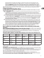
The LED indicators referred to below, and the clauses dealing with them, are sequenced as they may come on through
the course of the program.
LEDs #1 & 2
1
5
7 6
2
LEDs #5, 6 & 7
LED #10
LED #9
ampmatic
AMPS
LED #8
3
4
TURBO
FINAL
LEDs #3 & 4
1 and 2. INVERSE connections and input power
1. Connect the charger to a mains supply socket providing AC supply of 100 to 240V. The “POWER ON” LED #1
should illuminate and LEDs #3,4,5,6,7 should blink twice to confirm micro processor health.
HIGH and LOW intensity indication: The "POWER ON" LED #1 will reduce intensity to a low level to indicate low power
"ECO" mode. This will occur if there is no battery connected, or when a battery is connected and the program finds
itself in the Initial and Extended voltage retention test mode or the 'rest' periods of Maintenance Charge mode. The
"POWER ON" LED #1 will indicate brightly during Recovery charge, Bulk and Pulsed absorption charge and
Maintenance charge modes.
2. If the INVERSE POLARITY LED #2 indicates, the battery connections are incorrect. The charger is electronically protected
so no damage will result, and the output will remain disabled until the connections are corrected.
3. Recovery charge
If the battery is extremely flat (deep-discharged and sulfated), the recovery mode will engage and the DESULFATE LED
#3 will light. A special high voltage is applied to force a very small fixed current into the battery in a recovery attempt that may
last for a maximum of two hours. Initially the voltage is limited to about 16V for 5 seconds while the circuit assesses whether
this level is sufficient to recover the battery.
3.1 If the assessment is positive the voltage remains limited at 16V and the DESULFATE LED #3 remains on.
3.2 If the assessment is negative, typically for a badly neglected battery that has not received any charge for many months,
the second more powerful TURBO stage will engage with the voltage limit reset to 22V. TURBO RECOVERY mode is
indicated by a flashing DESULFATE LED #3.
3.3 Once the battery accepts the very low set current (0,4A LED #8 indicating) the voltage will reduce until the moment
6