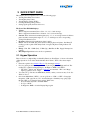
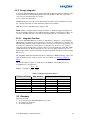
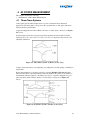
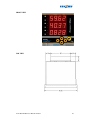
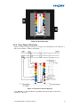
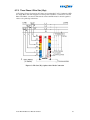
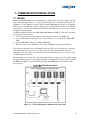
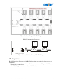
1
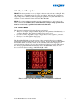
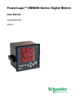
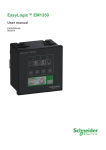
1
1. GENERAL
1.1. Customer Service and Support
Customer service and support is available via email at [email protected]. Please include the
model, serial number and a description with which we can re-create the problem at our Support
Centre. You can shorten this time by also including necessary settings, the wiring diagram and the
particular readings, which uniquely identify the problem.
Toll free phone support is available in some countries. For the latest phone number list please visit
www.conzerv.com
1.2. Product Warranty
CONZERV warrants all products to be free from defects in material, workmanship and title and will
be of the kind and quality specified in CONZERV’s written description in the manual. The
foregoing shall apply only to failures to meet said warranties, which appear within one year from
the date of shipping. During the warranty period, CONZERV will, at its option, either repair or
replace any product that proves to be defective. Please see the LIMITED WARRANTY
CERTIFICATE provided with the product for further details.
1.3. Limitation of Warranty
This warranty does not apply to defects resulting from unauthorized modification, misuse or use for
any reason other than electrical power monitoring.
OUR PRODUCTS ARE NOT TO BE USED FOR PRIMARY OVER-CURRENT
PROTECTION. ANY PROTECTION FEATURE IN OUR PRODUCTS IS TO BE USED
FOR ALARM OR SECONDARY PROTECTION ONLY.
THIS WARRANTY IS IN LIEU OF ALL OTHER WARRANTIES, EXPRESSED OR
IMPLIED, INCLUDING ANY IMPLIED WARRANTY OF MERCHANABILITY OR
FITNESS FOR A PARTICULAR PURPOSE. CONZERV SHALL NOT BE LIABLE FOR
ANY PENAL, INDIRECT, SPECIAL OR CONSEQUENTIAL DAMAGES ARISING FROM
ANY AUTHORIZED OR UNAUTHORIZED USE OF ANY CONZERV PRODUCT.
LIABILITY SHALL BE LIMITED TO THE ORIGINAL COST OF THE PRODUCT SOLD.
1.4. Statement of Calibration
Our instruments are inspected and tested in accordance with specifications published by an
independent testing facility. The accuracy and calibration of our instruments are traceable to the
National Institute of Standards and Technology through equipment that is calibrated at planned
intervals by comparison to certified standards.
1.5. Disclaimer
The information presented in this publication has been carefully checked for reliability; however, no
responsibility is assumed for inaccuracies. The information contained in this document is subject to
change without notice.
Power Max EM 6400 User Manual v02.04.01
2
CONTENTS
1.
GENERAL -------------------------------------------------------------------------------------------------------- 2
1.1.
1.2.
1.3.
1.4.
1.5.
2.
CUSTOMER SERVICE AND SUPPORT -------------------------------------------------------------------------- 2
PRODUCT WARRANTY ------------------------------------------------------------------------------------------ 2
LIMITATION OF WARRANTY ----------------------------------------------------------------------------------- 2
STATEMENT OF CALIBRATION --------------------------------------------------------------------------------- 2
DISCLAIMER ------------------------------------------------------------------------------------------------------ 2
OVERVIEW ------------------------------------------------------------------------------------------------------ 6
2.1.
PHYSICAL DESCRIPTION ---------------------------------------------------------------------------------------- 7
2.2.
FRONT PANEL ---------------------------------------------------------------------------------------------------- 7
2.2.1. The Indicators ---------------------------------------------------------------------------------------------- 8
2.2.2. The Keys----------------------------------------------------------------------------------------------------- 8
2.2.3. Here’s an example to try: --------------------------------------------------------------------------------10
2.3.
POWER MAX EM 6400 TECHNICAL SPECS ---------------------------------------------------------------- 10
2.3.1. Standard Measurements----------------------------------------------------------------------------------11
1.1.1.1. Accuracy -------------------------------------------------------------------------------------------------12
2.3.2. Auxiliary Power Supply ----------------------------------------------------------------------------------12
2.3.3. Front Panel Display --------------------------------------------------------------------------------------12
2.3.4. Installation and Input Ratings ---------------------------------------------------------------------------13
2.3.5. Environmental Conditions -------------------------------------------------------------------------------13
2.3.6. Dimensions and Shipping --------------------------------------------------------------------------------13
3.
QUICK START GUIDE ---------------------------------------------------------------------------------------14
3.1.
KEYPAD OPERATION ------------------------------------------------------------------------------------------ 14
3.1.1. Auto-Scroll -------------------------------------------------------------------------------------------------18
1.1.1. FAVOURITE (FAV) key: ---------------------------------------------------------------------------------18
3.2.
SETUP (PROGRAM) -------------------------------------------------------------------------------------------- 18
3.2.1. Editing the Setup ------------------------------------------------------------------------------------------19
3.2.2. Energy Integrator -----------------------------------------------------------------------------------------24
3.3.
4.
SUMMARY ------------------------------------------------------------------------------------------------------ 24
AC POWER MEASUREMENT -----------------------------------------------------------------------------25
4.1.
4.2.
4.3.
5.
3.2.2.1. Integrator Overflow----------------------------------------------------------------------------------------------- 24
THREE-PHASE SYSTEMS-------------------------------------------------------------------------------------- 25
CONSUMPTION AND POOR PF ------------------------------------------------------------------------------- 26
“3D” KVA MEASUREMENT---------------------------------------------------------------------------------- 26
MECHANICAL INSTALLATION--------------------------------------------------------------------------27
5.1.
INSTALLATION PROCEDURE --------------------------------------------------------------------------------- 30
5.1.1. Panel Mounting for New Installations------------------------------------------------------------------30
5.1.1.1. Location and Mounting considerations ------------------------------------------------------------------------ 30
5.1.1.2. Usage --------------------------------------------------------------------------------------------------------------- 30
5.1.1.3. Panel Considerations and Environment ------------------------------------------------------------------------ 30
5.1.1.4. Viewing ------------------------------------------------------------------------------------------------------------ 31
5.1.1.5. Mounting ----------------------------------------------------------------------------------------------------------- 31
6.
ELECTRICAL INSTALLATION ---------------------------------------------------------------------------32
6.1.
AUXILIARY (CONTROL) POWER SUPPLY ------------------------------------------------------------------ 33
6.2.
PTS AND CTS -------------------------------------------------------------------------------------------------- 33
6.2.1. PT, CT Wiring ---------------------------------------------------------------------------------------------33
6.3.
VOLTAGE SIGNAL CONNECTIONS--------------------------------------------------------------------------- 34
6.3.1. PT Connections--------------------------------------------------------------------------------------------34
6.3.2. Selecting the Voltage Fuses------------------------------------------------------------------------------34
6.4.
CURRENT SIGNAL CONNECTIONS --------------------------------------------------------------------------- 34
Power Max EM 6400 User Manual v02.04.01
3
6.4.1. CT Connections -------------------------------------------------------------------------------------------35
6.4.2. CT Polarity-------------------------------------------------------------------------------------------------35
6.4.3. CT Connection Reversal ---------------------------------------------------------------------------------36
6.5.
SETUP – SYSTEM TYPE --------------------------------------------------------------------------------------- 36
6.6.
PHASE LABELS ------------------------------------------------------------------------------------------------- 36
6.7.
CONNECTION DIAGRAMS ------------------------------------------------------------------------------------ 36
6.7.1. Power Max EM 6400 Rear Panel -----------------------------------------------------------------------36
6.7.2. Three Phase 3 Wire Delta--------------------------------------------------------------------------------37
6.7.3. Three Phase 4 Wire Star (Wye) -------------------------------------------------------------------------38
7.
COMMUNICATION INSTALLATION -------------------------------------------------------------------39
7.1.
RS-485---------------------------------------------------------------------------------------------------------- 39
7.2.
REPEATERS ----------------------------------------------------------------------------------------------------- 40
7.3.
FACTORY SETTINGS ------------------------------------------------------------------------------------------- 41
7.4.
MODBUS REGISTERS ------------------------------------------------------------------------------------------ 41
1.1.2. PHASE LABELS --------------------------------------------------------------------------------------------------- 42
7.4.1. Parameters not available on Display-------------------------------------------------------------------42
Power Max EM 6400 User Manual v02.04.01
4
Blank pages for notes
Power Max EM 6400 User Manual v02.04.01
5
2. OVERVIEW
The Power Max EM 6400 series of smart instruments offer comprehensive Three-Phase Electrical
Instrumentation and load management facilities in a compact and rugged package.
To get the best out of your investment, we suggest that you take a few moments to review this
Manual. This Chapter contains the main operating instructions. The remaining Chapters explain
the Installation and Setup steps before the Meter is ready for use.
The Power Max EM 6400 is a universal meter. Before use, please program the SYS
(measurement system configuration), PT and CT ratios through the front panel keys. Otherwise, it
will read your system incorrectly. Other settings such as communication parameters must also be
programmed as needed.
CONZERV stands behind your Power Max EM 6400 products with complete User Support and
Service. If the need arises, please do not hesitate to contact us at [email protected].
Figure 2.1: The Power Max EM 6400 Multi-function Load Manager
Power Max EM 6400 User Manual v02.04.01
6
2.1. Physical Description
FRONT: The front panel has 3 rows of 4 digits / characters each, with auto scaling “K” kilo,
“M” Mega and “-” minus indications. The “kilo” and “Mega” indications lit together show
Giga readings. Five smart-keys make navigating the parameters very quick and intuitive for
viewing data and configuring (Setup) the Power Max EM 6400.
REAR: The voltage and current terminals and the communication port are located on the
back of the meter. CAUTION: These contain hazardous voltages during operation and
must be operated only by qualified and authorized technicians.
2.2. Front Panel
The front panel contains the following indicators and controls:
• Three rows of display, 4 digits each that display three rms parameters simultaneously, or
one Energy Parameter. The displayed readings update every second.
• For each row: Kilo, Mega (Kilo + Mega = Giga) indicator and a Negative (-) indicator.
• Five keys to scroll through the display page.
The Power Max EM 6400 solves the problem of tiny cluttered indicators by prominently
displaying the parameter name right on the large readouts. For the first time in a Panel Meter,
the Parameter Name is as clearly readable as the value. The name will be displayed for 2
seconds as well as each time you press a key and then the Value for 8 seconds. This method
also allows programmable Phase Labels in the Power Max EM 6400 products. You can
choose from 123 (Factory setting), ABC, RYB, PQR, or RST.
Figure 2.2: The Power Max EM 6400 front panel with display and keypad
Power Max EM 6400 User Manual v02.04.01
7
2.2.1. The Indicators
Table 2.1: Kilo, Mega and Negative Indicators
M
Mega: When lit, indicates that the reading is in Mega, (10^6). 10,000 K is shown as
10.00 M. 1.0 M is displayed as 1000 K.
When Kilo and Mega are both glowing, the reading is in Giga (10^9). 10,000 M is
shown as 10.00 G. 1.0 G is shown as 1000 M.
-
Neg: - When lit, indicates that the reading is negative Per IEEE 100 and industry
standard practice by meter-men, the following are Negative:
• With Forward Flow of Watts: Capacitive (Leading) VARs and PF.
• With Reverse Flow of Watts: Inductive (Lagging) VARs and PF and Watts.
K
Kilo: When lit, indicates that the reading is in Kilo (10^3). 10,000 is displayed as
10.00 K. 1.0 K is shown as 1000.
Table 2.2: Giga, Mega (M), Kilo (K) and Decimal Point Scaling
RMS Reading
Indicator
Less than 0.001
K, M OFF, displays “0.000”
Less then 9999
K, M OFF
Above 9999
K ON, M OFF
Above 9999 k
M ON, K OFF
Above 9999 M
Giga (K + M indicators ON)
Upto 9999G
Above 9999G
Giga
Display shows “Hi” for positive numbers and “Lo” for negative
numbers
RMS readings are four digits. Energy readings have eight digits, including four additional
fractional digits. The maximum number the Meter handles is 9,999 G for RMS and Energy
values.
This means that the Energy readings of the meter will overflow at 3 values of kWh or kVAh
(selectable through set up) depending upon the PT and CT ratios programmed. See Table 3.4
“Integrator Overflow Value”
2.2.2. The Keys
Operating the meter is easy using the five smart keys to navigate through the Keypad
Operations Table . The Display Pages “expand” as you go right, much like the directory or
Explorer “tree” displayed on any computer. The display shows where you’re headed.
Power Max EM 6400 User Manual v02.04.01
8
Table 2.3: The Key pad operation table
Right Key:
• Go forward into sub-parameter pages.
• During Edit Setup values, select next (right side) digit.
Left Key:
• The Opposite of the Right key.
• Go Back towards to the Main Parameter Pages. Going Left past “PROG”
requires Code entry to enter Main Menu (Setup and Clear)
• During Edit Setup, selects previous (left side) digit
• Exits from Edit mode, back to the Main Menu.
Up Key:
• Scroll Up through Display Pages at the same level, within the same
Function.
• Continuous pressing for 3 seconds initiates limited Auto-scroll (within the
same Function). Press any key to return to manual scrolling.
• While editing, increases the value of the blinking digit during Edit.
Typically while changing the Meter Setup settings.
Down Key:
• The Opposite of the Up key.
Scroll Down through other Display Pages at the same level, through all
functions.
• Continuous pressing for 3 seconds initiates the Full Auto-scroll mode,
through all functions. Press any key to return to manual scrolling.
• While editing, decreases the value of the blinking digit during Edit.
Favourite (FAV) Key:
• The FAV key scrolls through the following pages: RMS (Home page),
VLL, A, F VLN, A, F VA, W, VAR W, VAR, PF PF1, PF2, PF3,
•
•
•
1, 2, 3 A 1, A 2, A 3 VA.d, R.d, t.r, MD, HR VAh
Wh R.VAh R.Wh t.VAh t.Wh. This gives simple one-touch access
to the most commonly used parameters, even for unskilled operators. “One
Touch” does not operate in the Setup (Program) Mode.
If you’re lost, the FAV key is a quick way to get back to the RMS home
page.
Continuous pressing for 3 seconds initiates Auto-scrolling through the
above FAV pages.
During the power up, if the FAV key is pressed, meter will go in to set
up mode. This is the simplest way to enter in to the setup.
The parameter name is displayed every 9th second for 2 seconds, as well as the first time you
press a key. At this point press the next key immediately to scroll to the next page you
want to see. If you are not sure which page you’re watching, one press of any key will
immediately identify the name. On pressing the key again immediately takes you to the
next page.
The Meter Menus and Displays are organized as below. Navigating with the Power Max
EM6400 is very easy and intuitive. For full details, see the Keypad Operations Table and the
Meter Function Map. The left-most column (RUN, CLR, SET) constitutes the “Main Menu”.
Press the key in the direction you want to go. Display shows where you’re headed.
Power Max EM 6400 User Manual v02.04.01
9
Press the key that takes you in the desired direction. You can’t cross the thick boundary.
Table 2.4: Menu and Display Map
Run
PROG
RMS
Main
Menu
V, A, F
V1, V2, V3
A1, A2, A3
IntG
VAh
Wh
CLR
SET
V pri
2.2.3. Here’s an example to try:
When you switch on a factory fresh meter, it starts at the “RMS” page, circled “1” in the
diagram below. This will be our “Home Page”.
From here, to now go to the VAh Energy Page, circled “3” in the diagram below:
1. Start at “RMS”
2. Go Down to “IntG” and
3. Go Right to “VAh”
There are no complicated key sequences, since the grouping of parameters is intuitive. The
keys always do what they say, under all modes.
RMS
1
V, A, F
V1, V2, V3
A1, A2, A3
INTG 2
VAh
3
Wh
Figure 2.3: Getting Around- an Example
A complete Keypad Operations Map appears in the next chapter. “RUN” constitutes the Main
Menu, along with “CLR” and “SET”, not shown above, but evident in the left-most “Main
Menu” (“RUN”, “CLR”, “SET”) column. To get into the Main Menu you first need to enter a
code.
2.3. Power Max EM 6400 Technical Specs
The Power Max EM 6400 Series is a high-accuracy, low cost, ultra-compact, power and
energy meter that offers ISO 9000 quality, accuracy and functional flexibility and MODBUS
RTU communications capability. The standard unit flush-mounts in a DIN 96 cutout.
The Power Max EM 6400 Series is designed for retrofit application such as replacement of
existing analog meters and is also usable as a stand-alone meter in custom panels, PDUs,
switchboards, switchgear, UPS’s, generator sets, MCCs systems etc.
The Power Max EM 6400 Series (except EM 6459) provides easy communication to PLCs,
DCS, BMS and other systems through the use of Modbus RTU communications on RS 485,
isolated to 2kV for 1 minute, from other circuits.
Power Max EM 6400 User Manual v02.04.01
10
The Power Max EM 6400 Series of products are configurable and programmable through the
front panel.
Measures true rms electrical parameters. 1 Second update
Wh accuracy : Class 1.0 as per IEC 62052-11 and 62053-23, class 0.5 is optional as per IEC
62052-11 and 62053-22 and ANSI C12.20.
Impulse: 6 kV IEC 60060 1.2 µS/50 µS.
Fast Transient: >2kV IEC 61000-4-4 Level 3
ESD IEC 61000-4-2
Emission meets CISPR 22
Power 4 Quadrant, Energy 2 Quadrant. Provides 3D power computation for kVA
2.3.1. Standard Measurements
The Power Max EM 6400 can measure, locally display and remotely transfer over MODBUS
RTU, the following electrical parameters over the input range with an accuracy of Class 1.0 or
better for Volts and Amps, Power and Energy functions, Class 0.5 is optional:
True rms voltage: phase-to-neutral and 3-phase average.
True rms voltage: phase-to-phase and 3-phase average.
True rms current: per phase and 3-phase average.
Real Power and Energy.
Reactive Power and Energy.
Power Factor.
Frequency.
The Power Max EM 6400 provides all single phase (per-phase) Real, Apparent, Reactive
Power and Power Factor values. Positive (Inductive) and Negative (Capacitive) Reactive
Energy is separately accumulated for Lead / Lag analysis.
Power Max EM 6400 User Manual v02.04.01
11
1.1.1.1. Accuracy
Table 2.5: Accuracy Table
Class 1.0 (standard) and Class 0.5 (ordering option)
Measurement
•
•
Accuracy
Class 1.0
Class 0.5
•
Voltage LN, per phase
1.0
0.5
•
Voltage LL, per phase
1.0
0.5
•
Voltage LN, avg
1.0
0.5
•
Voltage LL, avg
1.0
0.5
•
Amp, per phase
1.0
0.5
•
Amp, avg
1.0
0.5
•
Amp, Phase Angle per phase
2º
1º
•
Frequency
0.1
0.1
•
Real Power, (kW) Per Phase and Total
1.0
0.5
•
Reactive Power, (kVAR) Per Phase and Total
2.0
1.0
•
Apparent Power, (kVA) Per Phase and Total
1.0
0.5
•
Power Factor per phase and average
1.0
0.5
•
Active Energy, (kWh) Import/Export
1.0
0.5
•
Reactive Energy, (kVARh) (Ind / Cap)
2.0
1.0
•
Apparent Energy, (kVAh)
1.0
0.5
Note 1: Additional error of 0.05 % of full scale for meter input current below 200 mA.
Note 2: PF error limit is same as W error limit in %.
2.3.2. Auxiliary Power Supply
The meter needs a single-phase ac or dc Control supply to power its internal electronics.
Auxiliary supply voltage: 80 to 270 V ac or 100 to 270V dc.
Burden (load) < 3 VA (auxiliary supply).
2.3.3. Front Panel Display
•
•
•
•
•
Brilliant 3 lines, 4 digit (digit height 14.2 mm) per line, LED display with auto scaling
capability for Kilo, Mega and Giga.
The display provides the user access to all phase Voltages (phase to neutral and phase to
phase), Currents (per phase and total), Watts, VARs, VA, Power Factor, Frequency and
kWh, kVAh and kVARh.
The Power Max EM 6400 displays total volts, amps and frequency simultaneously.
Easy set up through keys located on the faceplate for common configuration parameters.
Password protection on setup parameters.
Power Max EM 6400 User Manual v02.04.01
12
2.3.4. Installation and Input Ratings
•
•
•
Auto-ranging voltage inputs should allow direct connection up to 500 VLL ac systems
(no PTs required up to 500 VLL phase to phase).
Supports (field configurable) direct 4-Wire Star (Wye), 3-Wire Star (Wye), 3- Wire Delta
configurations and single phase via Star (Wye) Phase 1.
3-phase voltage and current inputs
o Volts: 80 to 500 Phase-Phase,
o Amps: 50 mA to 6 A, Overload: 10 A continuous, 50 A for 3 seconds
o Field configurable for 5 A or 1 A secondary CTs
o Burden (Load): Less than 0.2 VA per Volt / Ampere input
o Frequency: 50 / 60 Hz (45 to 65 Hz )
2.3.5. Environmental Conditions
•
•
•
Sealed dust-proof construction. Meets IP51 for the front panel
Temperature Operating: – 10 to 60 °C, (14 to 140 °F)
Storage: – 25 to 70 °C, (-13 to 158 °F)
Humidity
: Below 5% to 95%, non-condensing
2.3.6. Dimensions and Shipping
•
•
•
Basic unit installed depth 80 mm behind bezel with 92x92 mm panel cutout, flush mount.
The Protection cover affixed over the rear Terminal Block extends the depth to 82 mm.
Bezel dimension 96 x 96 mm. Panel Cutout 92 x 92 mm
Weight 400 gms approx Unpacked, 500 gms approx Shipping
See Chapter 5: Mechanical Installation.
Power Max EM 6400 User Manual v02.04.01
13
3. QUICK START GUIDE
This Chapter shows at a glance, how to view the following pages:
• Viewing Three-Phase Total values
• Viewing Per-phase Values
• Viewing Energy Values (INTG)
• Clearing (Resetting) Energy Values
• Setting-up (Program) the meter before use.
The Power Max EM 6400 displays:
• Voltage:
Three voltage measurements Line-to-Line: 1-2, 2-3, 3-1 and Average,
Three voltage measurements Line-to-Neutral: 1-4, 2-4,3-4 and Average.
• Current: Three current measurements phase-wise: 1, 2, 3, one average current of all three
phases and three current phase angles Ao1, Ao2, Ao3 with respect to the corresponding
Voltage Line-Neutral vector.
• Frequency: Measured from whichever phase is active.
• Power: VA, W and VAR. Per phase and Total. PF per phase and 3phase. Per-Phase W
readings provide a quick CT Polarity Check. A negated W phase reading indicates CT
reversal.
• Energy: VAh, Wh, +VARh (Ind), -VARh (Cap), Run Hrs, On Hrs, Supply Interruptions
(outage)
• Kilo, Mega, Giga indication for the above parameters.
3.1. Keypad Operation
Table 3.1 shows a complete Map of all the Key Functions. Next Figure 3.1 shows a flowchart
of Key Operations. Look at the shaded left half, titled “Name”. Then, follow these simple
steps:
• First take a quick look at what the Keys do. Try the simple example.
• Now, try getting around to other parameters, by moving Up, Down, Right and Left. The
readings are organized as Display Pages to the Right of “RMS” and “INTG”.
o The “Kilo”, “Mega” and “Negative” Indicators are automatic. “Kilo” and “Mega”
light up together to show “Giga”.
• You cannot To go Left into the Main Menu (“RUN”) unless you enter an entry Code- See
Table 3.1 Note 1
• Once in the Main Menu (“RUN”), you can go Down to “CLR” or “SET”. Going right
though the “CLR” page allows you to clear the Integrator. Similarly, keep going right
through “SET” to program the meter settings. When done:
o Go Left all the way back to the Main Menu
o Go Up to “RUN”
o Go Right into RMS to view the Display Pages again.
Power Max EM 6400 User Manual v02.04.01
14
Table 3.1: Meter Function Map
Code
Note 1.
RUN
Name
Description
PROG
RMS
V LL
Start Here A
F
V 12
23
31
V LL =
A
=
F
=
V LN
A
F
V1
2
3
A1
2
3
V 1=
2=
3=
V LN =
A
=
F
=
VA
W
VAR.
AO 1
2
3
VA 1
2
3
AO 1 =
2=
3=
VA =
W =
VAR =
W
W
=
VAR =
PF =
W
VAR
PF
1
2
3
VAR 1
2
3
PF 1
2
3
THD
DM
INTG
V 00 1
2
3
A 00 1
2
3
VA.d
R.d
t.r
MD
HR
VA.h
W.h
VAR.h
-VARh
run.h
REV
R.VAh
Power Max EM 6400 User Manual v02.04.01
VLL: Voltage, phase to phase Avg.
V 12 = Voltage, rms phase 1 to phase 2
V 23 = Voltage, rms phase 2 to phase 3
V 31 = Voltage, rms phase 3 to phase 1
A: Current, Average F: Frequency.
Voltage, rms phase 1 to Neutral
Voltage, rms phase 2 to Neutral
Voltage, rms phase 3 to Neutral
VLN: Voltage, phase to Neutral, Average.
A: Current, phase wise, Average.
A 1 = Current, rms phase 1
2 = Current, rms phase 2
3 = Current, rms phase 3
F: Frequency in Hertz.
Current, Phase Angle of phase 1 in degrees.
Current, Phase Angle of phase 2 in degrees.
Current, Phase Angle of phase 3 in degrees.
VA: Volt-amperes, Total.
VA 1 = Volt-amperes, phase 1
VA 2 = Volt-amperes, phase 2
VA 3 = Volt-amperes, phase 3
W: Watt, Total
VAR: VAR, Total.
W: Watt, Total. Note : "-" Watts = reverse current
W 1 = Watts, phase 1
W 2 = Watts, phase 2
W 3 = Watts, phase 3
VAR: VAR, Total
PF: Power factor, Average.
VAR .1= VAR, phase 1.
2= VAR, phase 2.
3= VAR, phase 3.
Note : "-" Indicates Lead (Capacitive) VAR.
Power factor, phase 1.
PF 1 =
Power factor, phase 2
2=
Power factor, phase 3.
3=
Note: "-" Indicates Lead (Capacitive) Power factor.
V% .1= Voltage thd, Phase 1, Total Harmonic distortion, Phase 1
2= Voltage thd, Phase 2, Total Harmonic distortion, Phase 2
3= Voltage thd, Phase 3, Total Harmonic distortion, Phase 3
A% .1= Current thd, Phase 1, Total Harmonic distortion, Phase 1
2= Current thd, Phase 2, Total Harmonic distortion, Phase 2
3= Current thd, Phase 3, Total Harmonic distortion, Phase 3
VA.d =
VA demand (W.d= W demand, selectable through setup)
R.d =
Rising demand
t.r
=
Time remaining
MD =
Maximum demand
On hour at which the Maximum demand has occurred
HR =
VA.h =
Volt-ampere-hours.
Watt-hours. If watts is negative, VA.h, W.h, VAR.h, -VAR.h
W.h =
do not Integrate.
VARh = VAR-hours, Inductive.
-VARh= Negative VAR-hours, Capacitive.
Run hours. Total hours the Load was On. Accumulates when
run.h =
current is present.
R.VAh = Volt – ampere hours (export)
15
R.Wh
R.VAR
-R.VAR
R.Run.
TOT
t.VAh
t.Wh.
t.VAR..
-t.VAR.
t.Run
On.h
DIAG
DIA2
CLR
INTG
SET
Save
y/n
Intr
ID
Baud
Prty
Mdl.
Ver
Ver
1.000
9600
Evn.1
6400
03.02.
01.00
INTG
y/n
to
Clear
SYS
V.PRI
V.SEC
A.PRI
A.SEC
LABL
VA.Fn
d.SEL
d.PAR
d.Prd
baud
Prty
ID
STAR
415.0
415.0
5000.0
5.000
123
3d
Auto
VA
15.00
9600
EVn.1
1.000
R.Wh = Watt-hours (export).
R.VAR = VAR-hours, Inductive (export).
-R.VAR = Negative VAR-hours, Capacitive (export).
Run hours. Total hours the meter was run with reverse energy
R.Run =
flow (export)
t.VAh. = Total Volt – ampere hours (Import + Export)
t.Wh. =
Total Watt-hours (Import + Export).
t.VAR. = Total VAR-hours, Inductive (Import + Export).
-t.VAR. = Total Negative VAR-hours, Capacitive (Import + Export).
Total Run hours. Total hours the meter was run with current
t.Run =
input signals.
ON hours. Total hours the meter was ON. Accumulates if
On.h =
auxiliary supply is present (irrespective of input signals).
Intr =
Auxiliary interruption. Accumulates the auxiliary interrupt.
For factory testing only
For factory testing only
CLR =
to Edit
Setting
Clear. If "y", Clears all integrator parameters (above) to zero.
Choice of values
SYS = Power system'
s configuration* : Star (3E 4V3A),
Delta (3E 3V2A)
V.PRI = Voltage primary winding(PT) * : Line to Line: 100
V to 999 kV(415.0)
V.SEC = Voltage secondary winding(PT)* : Line to Line : 80
to 600 V(415.0)
A.PRI = Current primary winding.(CT)* : 1 A to 99 kA
(5000.0)
A.SEC = Current secondary winding.(CT)* : 1 to 6.5 A.
(5.000)
LABL = Phase labelling formats. : 123, RYB,RST, PQR,
ABC.
VA.Fn = VA function selection : 3d, Arth
d.SEL = Demand selection : auto, user *
d.PAR = Demand parameter : VA, W
d.PRd = Demand period : 5,10,15,20,25,30
baud = Baud rate : 1200, 2400, 4800, 9600, 19200.
Prty = Parity and Stop bit settings: EVn.1, EVn.2, Odd.1,
Odd.2, no.1, no.2
ID = RS485 Device ID number: 001 to 247. (Evn.1 = Even. 1
stop bit)
*changing these values while the device in use, is not
recommended
Default set up values are given in bold and italics
KEY FUNCTION MAP NOTES:
1. To Clear Integrated values or Set meter settings, you must first enter the Main Menu.
2. Go Up to “PROG”, then Left to enter the Main Menu. See Map or Table 3.1.
• You must now enter the Factory Set code of 1000, to proceed.
o "CODE y”, followed by the entry of the Code “1000" is required.
o To enter the code, edit the blinking digit value up or Down to get “1000”.
o Keep going Left.
o Without entering the code, you may view the settings, but you can’t change them.
Within the “SET” page options, the Factory settings are shown Bold Text in the right side
column above.
Power Max EM 6400 User Manual v02.04.01
16
2
Code
y
5
PROG
4
RUN
V
A
F
RMS
V
A
F
LL
6
Legend
V
12
23
31
LN
1
2
3
A
1
2
3
A°
VA
W
VAR
5
THD
Use
1
V
W
VAR
PF
Vºo 1
2
3
Aºo 1
2
3
REV
1
2
3
W
1
2
3
VAR
3
PF
1
2
VA.d
R.d
t.r
MD
HR
INTG
keys
or
keys
key only
3
R.VAh
R.VAR
-R.VAR
R.run
TOT
t.VAh
t.Wh
1
2
3
6
DM
Use
or
R.Wh
1
2
3
VA
Use
t.VAR
THD = with
THD option
only
-t.VAR
t.run
VAh
On.h
Wh
INTR
VARh
DIAG
-VARh
1.000
9600
Evn 1
2
1
6400
02.04
01.00
run.h
RS-485
status
Factory
QA only
3
4
Figure 3.1: The Run Mode Flow chart
Power Max EM 6400 User Manual v02.04.01
17
3.1.1. Auto-Scroll
Auto-Scroll allows you to monitor a group of Display Pages sequentially, every 5 seconds,
without constant key pressing. This is convenient for viewing from a distance. Since the
Power Max EM 6400 displays the Parameter Name (1sec) followed by the Value (4 sec) on
the same large displays, both are equally readable from a distance. No more squinting at a
clutter of parameter indicators.
To enter auto-scroll, go to the desired display page and keep the Up or Down key
pressed for minimum 3 seconds, then release key. The display flashes “AUTO” and then
automatically scrolls through other pages at the same level (column in the above table). Press
any key to revert to Manual Scrolling.
• The Up key enters Limited Auto-scroll – within the same Group, e.g. only “RMS” or
only “INTG”.
• The Down key enters Full Auto-scroll- down the entire column of pages.
1.1.1. FAVOURITE (FAV) key:
The FAV key scrolls through the following pages:
’VLL, A, F’ ‘VLN, A, F’ ‘VA, W, VAR’ ’ W, VAR, PF’ ‘PF1, PF2, PF3’ ‘
1,
2,
3’
‘A 1, A 2, A 3’ ‘VA.d, R.d, t.r’ ‘MD, HR’ ‘VAh’ ‘Wh’ ‘R.VAh’ ‘R.Wh’ ‘t.
VAh’ ‘t. Wh’. This gives simple one-touch access to the most commonly used parameters,
even for unskilled operators. “One-touch” does not operate in the Setup (Program) Mode.
Optional parameters are with bold characters.
• If you’re lost, the FAV key is a quick way to get back to the RMS home page.
• Continuous pressing for 3 seconds initiates Auto-scrolling through the above FAV pages.
3.2. Setup (Program)
The meter must be set (programmed/configured) to match the application settings, before use.
Otherwise, the readings will be wrong. All the Setup values can be re-programmed at any
time, upon entering “SET” However, the settings: SYS (Star/wye or Delta), Vpri, Vsec, Apri,
Asec critically determine the scaling of measured readings. While the scaling may be used to
tune out Instrument Transformer errors, wrong settings will upset the readings of running
systems. It is the user’s responsibility to ensure that only qualified personnel correctly Set-up
the Meter.
Power Max EM 6400 User Manual v02.04.01
18
Table 3.1a: Entering in to setup
Action
From the “RMS” or “INTG”
page, go Up
Then go Left .
Display
PROG
"Code y"
"Code y" is displayed. “y"
blinks.
To proceed with Code Entry:
The code is Factory Set to
1000. Press to enter each
digit. Three times totally.
Press to decrement “2".
Press to enter the Main
Menu.
"000 0"
"2 000"
" 1 000"
" 0000"
“PASS”
“RUN”
Or,
“FAIL”
Now press
Again press
Press to get into setup
Once you’re done, re-trace
your path: and .
Remember “Save Y”
“CLR”
“SET”
“SYS”
“V.PRI”
“V.SEC”
“RUN”
Remarks
The meter is about to enter the Main Menu.
“y" blinks.
To proceed with Code Entry, we need to enter
the Main Menu.
• Go Left .
Or, to abort and re-enter RMS:
• Press .
Or, to only view setup, (no edit):
• Press or to toggle “y” to “n".
• Press to enter Main Menu.
"Fail" is flashed, then "RUN" is displayed.
The blinking digit indicates the cursor.
We have now entered the Units, Tens and
Hundreds digits. The Thousands digit needs to
be changed from 2 to 1.
Now the Code of 1000 is almost in.
Notice that a “0” quickly hides each code-digit
you enter.
“RUN” indicates a successful entry into the
Main Menu. Congratulations!
If you were not successful, don’t despair; you
can have another go from the top of this Table.
Briefly switching off the Meter will easily
return you to the RMS page, the starting point.
You are at the Setup page.
Go
Go
to see other Settings.
to see and change their values.
You’re now at the top of the Main Menu. Go
. You’ll see RMS. You can now go or
to view all the display pages.
3.2.1. Editing the Setup
First, take a look at the Table 2.3 (Keypad Operations Table). Locate the Shaded, Bold
display pages below.
To enter “SET” and change a Setting value, the sequence (shown below) is: 1, 2, 3, and 4
along the way, the following must be observed:
• The Password Code must be entered to change the Setup. The code offered will read
“0000”. Edit ( , ) the blinking Digit to achieve “1000”. Press when done with each
digit, to keep moving towards the “Run” page. The Meter accepts each digit entered, but
masks it with “0000” so someone watching doesn’t steal the password.
After changing the desired Setup values (Step 4), the sequence to get back to the RMS
page is: 5, 6, 7, 8.
•
Exiting Setup requires you to Save the settings (Step 6). “SAVE Y”, press .
To Discard the changes, toggle Up or Down to get “SAVE N” before pressing .
Power Max EM 6400 User Manual v02.04.01
19
Going forward from 7 (RUN) to 8 (PROG) does not require any Code. You go
through..
Legend
Code Entry
Main
Menu
Password
Code
1000
RUN 2
Code
Y
, straight
Use
or
keys
Use
or
keys
Use
key only
1
To PROG
Mode
PROG
7 To RUN Mode
8
CLR
SET
RMS
Setup
3
Name
Save
Y
Value
New
Value
4
5
6
Enter the New Value.
Figure 3.2a: Entering and Exiting Setup
Legend
To program via code entry
RUN
FAIL,
View
only
PASS
CODE
‘y’
20 0 0
PROG
Use
or
keys
Use
or
keys
Use
key only
10 0 0
Code EntryFAIL
view
only
CLR
CODE
‘n’
RMS
SET
Figure 3-2b: Code entry for Entering Setup
Power Max EM 6400 User Manual v02.04.01
20
RUN
CLR
FAIL
(View
only)
2000
PASS
10 0 0
INTG
DM
PASS
FAIL
FAIL
view
only
INTG ‘y’
PASS
INTG ‘n’
FAIL
DM '
y'
PASS
DM '
n'
FAIL
Name
SET
CODE
‘y’
PROG
To program via code entry
CODE
‘n’
RMS
Legend
Use
Value
SYS
V. PRI
V SEC
STAR
415.0
415.0
V. PRI
V. SEC
A. PRI
415.0
415.0
0100.
SAVE
‘y’
V. SEC
A. PRI
A. SEC
415.0
100.0
5.000
SAVE
'
n'
A. PRI
A. SEC
LABL
0100.
5.000
123
A Sec
LABL
VA.Fn
5.000
123
3d
LABL
VA.Fn
baud
123
3d
9600
VA.Fn
baud
PRTY
3D
9600
Evn.1
Baud
PRTY
Id
9600
Evn.1
1.000
PRTY
ID
Evn.1
1.000
ID
1.000
Use
or
or
Use
New value
(Steady
display)
Figure 3.2c: The complete Setup (Program) menu
Power Max EM 6400 User Manual v02.04.01
keys
key only
Setup starts with SYS
Edit
Blinking
Digit
keys
21
Table 3.2: Editing the Setup Values
First, you must enter the Main Menu and reach “SET” using the previous Table. This example
illustrates changing System Mode (SYS) from “STAR” to “DELTA”.
Action
Display
Remarks
"SET" You’re in the Main Menu.
Press
. Enter Setting
We have now reached SyS (top
row) for editing.
Press to view Value.
Press to edit SYS value.
The value blinks.
Press
to change to Delta 2E.
Press
to accept the value.
We’re done. Press
back.
Press again.
Press
SyS
V.PRI
V.SEC
"STAR"
415.0
415.0
Wiring System.
Voltage primary.
Voltage secondary.
Wiring System = Star 3E, 4V3A
Voltage primary = 415V.
Voltage secondary = 415V.
"STAR” Blinks. Only Top Row is edited
415.0 Ignore
415.0 Ignore
" DLTA " Blinks. (Note: To discard the change:
415.0 • Press .
415.0 • Restores the previous value.)
"DLTA" Steady. Sys is now set to Delta.
415.0 Press to scroll down, and to change
415.0 other values.
to head
" SYS "
Blinks
"SAVE"
"y"
to accept "y" (yes, save) "PASS"
“SET”
NOTE: To discard present changes, press to
show “SAVE n”.
“PASS” flashes and Stores the Setup changes.
Now, you’re back in the Main Menu and can
go to “RUN” and to “RMS”.
Table 3.3a: Clearing the Energy Integrator and Max Demand (W.h, VA.h, VAR.h, VAR.h, etc.)
Action
Display
Remarks
Use Table 3.1 to enter the Main
Menu.
Press to reach “CLR”
"CLR" You’re in the Main Menu.
Press
to enter CLR mode.
"INTG"
Press
to proceed with CLR
"INTG y Clear INTG? Yes!
"
NOTE: escapes back to Main Menu
Press
to Clear.
"PASS" “PASS” flashes INTG and Max demand
"INTG" Cleared.
To head back, press
“CLR” Now, you’re back in the Main Menu and can
go to “RUN” and to “RMS”
Power Max EM 6400 User Manual v02.04.01
22
Action
Table 3.3b: Clearing only the Maximum Demand
Display
Remarks
Use Table 3.1 to enter the
Main Menu.
Press to reach “CLR”
"CLR"
Press
"MD"
to enter CLR mode.
Select the parameter
or
You’re in the Main Menu.
“INTG” or Select which parameter to be deleted
“MD”
Press
to proceed with CLR
"MD y "
Clear MD? Yes!
NOTE: escapes back to Main Menu
Press
to Clear.
"PASS"
"MD"
“PASS” flashes and ‘MD’ cleared and ‘MD’
displayed.
“CLR”
Now, you’re back in the Main Menu and
can go to “RUN” and to “RMS”
To head back, press
Legend
To program via code entry
RUN
CLR
FAIL
View
only
2000
PASS
10 0 0
INTG
MD
CODE
‘y’
FAIL
view
only
INTG
‘y’
PASS
INTG
‘n’
FAIL
MD
'
y'
PASS
MD
'
n'
FAIL
PROG
Use
or
keys
Use
or
keys
Use
key only
CODE
‘n’
RMS
Figure 3.2d: Clearing the Integrator and Demand
Power Max EM 6400 User Manual v02.04.01
23
3.2.2. Energy Integrator
Your Power Max EM 6400 meter is equipped with Energy Integrator function which provides
several parameters for Energy Management: VAh, Wh, VARh, -VARh, run.h (run hours),
on.h (on hours), Intr (Interruptions / outages).
A few of these need explanation:
run.h: Indicates the period the Load is ON and has run. This counter accumulates as long as
any one Amps phase has more than 10mA through the meter terminal.
on.h: The period for which the meter (supply) is ON.
INTR: Number of Supply Outages, means the number of Auxiliary Supply interruptions. If
the meter Auxiliary Supply is from a UPS then the Intr (number of interruptions) will be zero
(as long as the UPS stays ON), even if the Voltage Signals did die out from time to time.
3.2.2.1. Integrator Overflow
Your Power Max EM 6400 meter contains a comprehensive “Integrator” to support Energy
Management. It accumulates several parameters over time, as explained above. All values are
Direct Reading and have a high resolution. This is necessary for accurate energy analysis over
short intervals of time. It also means that the readings max out and reset sooner or later as
given below. Since the Integrator contains counters for several parameters (VAh, Wh, VARh,
-VARh, Run Hours, On Hours, Interruptions), they all reset together whenever any one of
them (usually VAh) overflows. This makes energy management calculations such as Average
PF very easy.
The maximum number that the Meter handles is 9,999 Giga for RMS and Energy values. The
value at which the meter overflows is given below. See Table 3.4 “Integrator Overflow
Period”.
The Overflow Period depends on the Product of the PT Ratio and CT Ratio that you’ve
programmed for your application.
PT Ratio * CT Ratio =
Vpri
V sec
x
Apri
A sec
Table 3.4: Integrator Overflow Period
PT Ratio x CT Ratio
Max Reading
1 to 1.999
2 to 10.999
11 to 100.999
101 to 1000.999
1001 to 10000.999
10001 to 100000.999
Greater than 100001
9.999x10⁶
9.999x10⁷
9.999x10⁸
9.999x10⁹
9.999x10¹⁰
9.999x10¹¹
9.999x10¹²
Overflow Period (Months)
Max
Min
3.85
1.92
19.29
3.51
35.07
3.82
35.07
3.82
35.07
3.82
35.07
3.82
35.07
3.82
3.3. Summary
We have now learnt
1. To operate the Power Max EM 6400 Series products.
2. To configure its Setup and
3. To Clear its Integrator.
Power Max EM 6400 User Manual v02.04.01
24
4. AC POWER MEASUREMENT
This Chapter describes the following:
1. Fundamentals of Three-Phase Measurements
4.1. Three-Phase Systems
A three-phase system delivers higher levels of power for industrial and commercial
applications. The three phases correspond to three potential lines. A 120° phase shift exists
between the three potential lines.
A typical configuration has either a Delta connection or a Wye (Star) connection (see Figure
4.1, below).
In a three-phase system, the voltage levels between the phases and the neutral are ideally
defined by V1 = V2 = V3 = V12 / 3 = V23 / 3 = V31 / 3. In practice, there will be some
unbalance (difference).
Figure 4.1: Three-Phase System: (1) Delta, (2) Star (Wye)
Voltages between the phases vary depending on loading factors and the quality of distribution
transformers.
Power measurement in a poly phase system is governed by Blondel's Theorem. Blondel’s
Theorem states that in a power distribution network, which has N conductors, the number of
measurement elements required to determine power is N-1. A typical configuration of poly
phase system has either a Delta connection or a Star (Wye) connection (see Figure 4.2
below).
Figure 4.2: Poly Phase System: (1) Delta, (2) Star (Wye)
Power Max EM 6400 User Manual v02.04.01
25
4.2. Consumption and Poor PF
CONSUMPTION: Wh = W x T, where W = instantaneous power T = time in hours
The total electric energy usage over a time period is the consumption of Wh.
Typically, the unit in which consumption is specified is the kilowatt-hour (kWh): one
thousand watts consumed over one hour. Utilities use the Wh equation to determine the
overall consumption in a billing period.
POOR POWER FACTOR: Results in reactive power consumption. Transferring reactive
power over a distribution network causes energy loss. To force consumers to correct their
Power Factor, utilities monitor reactive power consumption and penalize the user for Poor
Power Factor.
4.3. “3D” kVA Measurement
The Power Max EM 6400 is equipped with 3D Measurement of kVA. This advanced method
provides the most accurate and predictable measurement under unbalanced as well as
distorted waveform conditions.
However, in case the Power Max EM 6400 needs to match the reading of older or simpler
meters, which use the Arithmetic kVA definition, this too is available as a Set-up option.
Table 4.1: VA Function Set up Options
kVA Function
3D (Factory
setting)
Formula
kVA 3D =
W2 +
VAR2 +
Other Names
D2
Where D = Distortion Power per IEEE 100
Arth
Power Max EM 6400 User Manual v02.04.01
Which one?
U, Apparent,
Vector kVA
Best, all around
Arithmetic,
Scalar kVA
Good under Low
unbalance, to
match simpler
meters without
3D capability
26
5. MECHANICAL INSTALLATION
The Power Max EM 6400 is panel-mounted and has reliable, rear-mounted terminal strips
rated at 500v. The 92 x 92 mm cut-out and 96 x 96 mm bezel dimensions adhere to DIN
43700.
Depth required behind the Bezel is 80 mm, plus space for wiring. Two side clamps are
provided for firm mounting.
CAUTION
:
All Installation, wiring and maintenance instructions to be carried out by
qualified personnel only.
Please read
proceeding
this and
the following chapter completely, before
These diagrams display the various dimensions of mechanical installations.
SIDE VIEW
REAR VIEW
Power Max EM 6400 User Manual v02.04.01
27
FRONT VIEW
TOP VIEW
Power Max EM 6400 User Manual v02.04.01
28
RECOMMENDED CUTOUT
92 x 92 mm
Not to scale
Power Max EM 6400 User Manual v02.04.01
29
5.1. Installation Procedure
5.1.1. Panel Mounting for New Installations
5.1.1.1. Location and Mounting considerations
DANGER
:
All Installation, wiring and periodic maintenance of the Power Max EM 6400
as well as its associated circuits involve high voltages and currents. While
this manual suggests several safety and reliability steps, it must be used in
conjunction with the safety codes in force at your location. Failure to
practice safe working procedures is likely to cause damage to the
installation, severe injury and / or death. All work including handling of
electrical circuits during Installation, only qualified personnel must do
wiring and periodic maintenance.
Neither CONZERV nor its agents may be held responsible for damage or
death arising out of the wiring and / or PT, CT or other external circuits.
The covers of the Power Max EM 6400 should never be dismantled or
opened. There are no user-serviceable parts inside. The Power Max EM
6400 contains high-precision components, which require special handling
available only at authorized CONZERV service locations. High voltages are
likely to be present inside even after the Power Max EM 6400 has been
switched off. Opening the covers of the Power Max EM 6400 and/or any
attempts to dismantle, service, repair or modify the unit by unauthorized
persons may cause severe injury, will damage the unit and will also render
CONZERV’s warranty void.
5.1.1.2. Usage
First, decide on how the Power Max EM 6400 is going to be used. If you do not already have
an Energy Management programme in operation, then your Energy Consultant should be able
to help you identify which load(s) offer maximum savings potential. This will help you
decide: Which point is to be monitored, where the readings will be viewed from, who must
have access to the instrument and how often. For best performance, choose a location, which
provides all the required signals with minimum wiring lengths.
5.1.1.3. Panel Considerations and Environment
The Power Max EM 6400 is a high - precision measuring instrument and its operating
environment is of utmost importance. For maximum performance, the instrument should be
mounted in a dry, dust-free location, away from the heat sources and strong electromagnetic
fields. To operate reliably, the following conditions must be met:
Storage Temperature : -25O to 70o C, (-13O to 158OF)
Operating Temperature: -10O to 60o C, (14O to 140OF)
Relative Humidity
: 5% to 95%, non-condensing.
The Power Max EM 6400 should be separated from other equipment and sufficient space
must be provided all around for cooling air to rise vertically past the instrument. The cooling
air temperature must be below the specified operating temperature.
The panel or housing, in which the Power Max EM 6400 is mounted, should protect it from
dust, moisture, oil, corrosive vapours, etc.
Power Max EM 6400 User Manual v02.04.01
30
The panel doors must be easily opened to provide easy access to the Power Max EM 6400
wiring for trouble-shooting. Allow clearance if the unit is going to swing out, as well as
adequate slack in the wiring. Allow space for terminal blocks, CT shorting blocks, fuses,
auxiliary contractors and other necessary components.
5.1.1.4. Viewing
For ease of operation, in the location should be preferably at, or slightly above, eye-level. For
viewing comfort, minimize glare and reflections from strong light sources.
5.1.1.5. Mounting
Before Mounting and Wiring, the Setup procedure (see section 3.2) should have been
completed.
The Power Max EM 6400 is panel mountable.
Panel cut-out
92+0.5-0 (w) x 92+0.5-0 mm (h) DIN 43700
Panel Thickness
Instrumental Bezel dimension
Depth behind Bezel
Mounting Clamp Screws
Terminal Screws
0.5 to 4.0 mm
96 x 96mm
80 mm. Leave clearance for wires. 82 mm with
Terminal Cover
Slotted, 2 nos
Combination Phillips and Slotted head
The cut-out should be punched with the proper tool and should be free from burrs.
Before Wiring, insert the Power Max EM 6400 into the cutout from the front. Then, fasten the
two side clamps from the rear. While supporting the Power Max EM 6400 from the front,
tighten both side clamp screws in a criss-cross pattern till all slack is taken up and then apply
one full turn. Do not over-tighten.
Power Max EM 6400 User Manual v02.04.01
31
6. ELECTRICAL INSTALLATION
DANGER
:
All Installation, wiring and periodic maintenance of the Power Max EM 6400
as well as its associated circuits involve high voltages and currents. While
this manual suggests several safety and reliability steps, it must be used in
conjunction with the safety codes in force at your location. Failure to
practice safe working procedures is likely to cause damage to the
installation, severe injury and / or death. All work including handling of
electrical circuits during Installation, wiring, periodic maintenance must be
done only by qualified personnel.
Neither CONZERV nor its agents may be held responsible for damage or
death arising out of the wiring and / or PT, CT or other external circuits.
The covers of the Power Max EM 6400 should never be dismantled or
opened. There are no user-serviceable parts inside. The Power Max EM
6400 contains high-precision components, which require special handling
available only at authorized CONZERV service locations. High voltages are
likely to be present inside even after the Power Max EM 6400 has been
switched off. Opening the covers of the Power Max EM 6400 and/or any
attempts to dismantle, service, repair or modify the unit by unauthorized
persons may cause severe injury, will damage the unit and will also render
CONZERV’s warranty void.
This Chapter describes the following:
• The Need and selection of Potential Transformers (PTs) and Current Transformers (CTs)
• Auxiliary Supply, PT and CT Connections
NOTE: For best wiring results with the new Terminal cover, please ensure the following
specs:
Improper wire-man-ship will damage the Terminals and require Factory Replacement.
This does not indicate defective manufacture and is not covered by product warranties.
• Power Driver preferred, Hand Screw-Driver OK.
• TIP: Phillips preferred, DO NOT USE POZIDRIV TIPS. Flat OK
Screw Head Diameter = 3.5mm, TIP Shaft Diameter < 5mm.
IMPORTANT - Driver Shafts inserted angularly or of Diameter = 5mm or more WILL GET
STUCK in the Safety Cover
Tightening Torque: (25 to 60) N-cm
Loosening Torque: (55 to 60) N-cm
Screw Travel: 6 mm less wire thickness
Torque greater than 60 N-cm may strip the screw or break the Safety Cover.
Worn-out bits and insufficient hold-down pressure while tightening will cause the bit to ride
on the screw head thus stripping and damaging it.
Power Max EM 6400 User Manual v02.04.01
32
6.1. Auxiliary (Control) Power Supply
The Power Max EM 6400 requires a Single-phase ac / dc Auxiliary (Control) Power Supply
to supply power to its internal electronic circuitry. The Setup procedure (Section 3.2) must
first be completed, with only the Auxiliary Supply connected.
External surge suppressors are necessary in the Auxiliary Supply Circuit for proper operation
during extreme surge conditions, where the voltage surges exceed the Auxiliary Supply limits
(E.g. Rural areas and outlying areas prone to lightning strikes).
Auxiliary Supply Range:
• 80 to 270V ac / 100 to 270V dc.
• Burden (load) < 3VA (Auxiliary).
NOTE 1: The Auxiliary Power Supply may be derived from the voltage signals.
NOTE 2: If you have a 440 v Three-Wire Delta system and a reliable Neutral is not available,
a 440v: 240v Supply transformer should be used to provide the standard 240v Auxiliary
Supply.
DANGER
: Do not feed the Power Max EM 6400’s auxiliary power
supply terminals with a voltage greater than the rating marked on the
label. The Power Max EM 6400 will be permanently damaged and
CONZERV’s Warranty shall be void.
6.2. PTs and CTs
Large electrical installations have high voltages and currents, which may exceed the direct
connection rating of the meter. In this case, Potential Transformers (PTs) and Current
Transformers (CTs) are used to precisely “step down” or reduce the voltage and current level
to suit the meter rating. Potential Transformers usually have a full-scale output of 110V ac
rms line-line and Current Transformers, a full-scale output of 5A or sometimes 1A.
The PTs (Potential Transformers) and CTs (Current Transformers) must be planned, installed
and tested by a qualified electrical contractor before wiring the meter. The accuracy of the
measurement also depends on the accuracy and phase – angle error of the PTs and CTs.
Instrument Class 1 or better PTs and CTs are recommended. Do not use Protection Class
(10P10, etc.) CTs to feed the Power Max EM 6400; they have poor accuracy and phase
characteristics.
Ensure that the CT Primary rating has been selected so that your normal load variation lies
between 40% and 80% of its full scale. If your CT is over-rated, say if the load is always less
than 10% of the CT Primary rating, accuracy suffers. On the other hand, if the CT is underrated, then you may exceed its full-scale and burn out both the CT and the Power Max EM
6400.
6.2.1. PT, CT Wiring
The PTs and CTs must have adequate VA rating to support the burden (loading) on the
secondaries. You may want to support the Auxiliary supply burden from one of the PTs. CT
wiring can impose additional burden (loading) on the CT. For example, if the CT has a 5A
secondary and the wire resistance is 1.0 , then the CT has to support an additional burden of
5VA. If the wiring distance from the CT secondary is greater than stated in Table 6.1, then the
CT could get over-burdened and give large errors. Choosing a 1A CT secondary can reduce
this error. The CT Secondary value must be user programmed into the meter.
The Power Max EM 6400 should be conveniently located for easy connections of voltage
(PT) and Current (CT) signals, the auxiliary (control) supply.
Power Max EM 6400 User Manual v02.04.01
33
NOTE 1: The Power Max EM 6400’s Field Programmable PT and CT Primary or secondary
Settings may be utilized to Calibrate out the PT and CT amplitude error, for improved
accuracy.
6.3. Voltage Signal Connections
For proper meter operation, the voltage connection must be maintained. The voltage must
correspond to the correct terminal. The cable required to terminate the voltage sense circuit
should have an insulation rating greater than 600V ac and a current rating greater than 0.1A.
There are 4 Voltage input terminals marked V1, V2, V3 and Vn. See the wiring diagrams
that follow, for details. For Delta connection, the Vn terminal should be left unconnected.
6.3.1. PT Connections
The EM 6000 directly accepts LT voltage inputs of up to 500 V ac rms Line to Line.
Voltages greater than this, typically HT systems, must be connected through Potential
Transformers (PTs). The Power Max EM 6400 allows Field Programming of both PT Primary
and Secondary voltages. See the voltage input overload graph for more detail
Field Programmable PT Primary range
: 0.1 to 999 kV ac rms L-L.
Field Programmable PT Secondary range : 100 to 500v ac rms L-L.
Power Max EM 6400 Voltage Input burden : 0.2 VA per input.
See Section 3.2 (Setup (Field Programming) section) for programming details.
IMPORTANT: The PT Primary and Secondary values must be User Programmed
before using the Meter. Otherwise, the readings will be wrong.
CAUTION
: Before wiring, de-energize the PT secondary by opening
the circuit or removing the fuse. Do not short the PT secondary.
6.3.2. Selecting the Voltage Fuses
We strongly recommend using fuses on each of the sense voltages and the control / auxiliary
power, although connection diagrams often do not show them. Use a 1A fuse on each voltage
input.
6.4. Current Signal Connections
The meter accepts up to 6A ac rms per channel directly. Above that, a Current Transformer
must be interposed to scale down the current.
There are three pairs of Current Input terminals marked A1, A2 and A3. Each pair of input
terminal is labelled as (S1, S2) and has an arrow indicating the direction of current flow. For
proper measurements, the phase identification as well as the polarity of the current signals
must be correct. The Forward flow (Import by consumer) current direction must be into the
S1 terminal and the exit from the S2 terminal. Please maintain the correct sequence and
polarity to avoid wrong readings.
Any unused current input terminals (e.g. A2 (S1, S2) for Delta) must be shorted together. The
shorted terminals do not need to be grounded.
Power Max EM 6400 User Manual v02.04.01
34
Install the wiring for the current circuit at 500V ac insulation as a minimum. The cable
connection should be rated for 7.5A or greater and have a cross-sectional area of 16AWG
minimum.
CAUTION
: Before wiring, de-energize the CT secondary by shorting
it via a shorting block.
Under no circumstances must the CT secondary be left open-circuited,
even momentarily, when primary current is flowing. This causes high
voltages that will overheat and explode the secondary of the CT and
damage the instruments as well.
6.4.1. CT Connections
Mount the current transformers (CTs) as close as possible to the meter for best accuracy. The
following table illustrates the maximum recommended distances for various CT sizes,
assuming the connection is via 16AWG cable.
Table 6.1: CT Size and Maximum Distance
5A CT Size
2.5 VA
5.0 VA
7.5 VA
10.0 VA
15.0 VA
30.0 VA
Maximum Distance (CT to Meter)
10 Feet
15 Feet
30 Feet
40 Feet
60 Feet
120 Feet
Field Programmable CT Primary range
: (1A to 999kA) ac.
CT Secondary
: (1A or 5A) ac (programmable)
Other values are also programmable to compensate CT errors if desired.
EM 6000 CT burden
: 0.2VA maximum per input.
See the Setup (Field Programming) section for programming details.
IMPORTANT: The CT Primary and Secondary values must be User Programmed
before using the Meter. Otherwise, the readings will be wrong.
NOTE 1: With Dual - Range CTs, select the best range for programming the Power Max EM
6400. Do not change the range thereafter without re-programming the Power Max EM 6400;
the Power Max EM 6400 will read erroneous values.
6.4.2. CT Polarity
When the meter is connected using the CTs, you must maintain the correct CT polarities. CT
polarities are dependent upon correct connections of CT leads, and upon the direction the CTs
are facing when clamped around conductors. The dot on the CT must face the line side; the
corresponding secondary connection must connect to the appropriate input on the meter.
Failure to connect CTs properly results in inaccurate power readings. If your meter is not
reading power properly, it is more than likely that the CT is incorrectly wired. If one or two
CTs are reversed, then Energy parameters accumulate only one phase value. If two or all the
phases of the CT are reversed, Energy will not accumulate. (Energy Export will not be
measured).
Power Max EM 6400 User Manual v02.04.01
35
6.4.3. CT Connection Reversal
To check the polarity of the CT after the meter has been installed, simply look at the phasewise W (Watt) readings to see that each of the readings are positive (assuming you are
consuming power). If one of the W readings is negative, that particular phase CT is reversed
and must be corrected. On the other hand if you are exporting power, all three phase-wise W
readings must be negative.
6.5. Setup – System Type
The Power Max EM 6400 needs to know what type of 3-phase system it is connected to. This
is programmed in the Setup procedure (Section 3.2), before using the meter. The meter does
allow you to change this setting while it is running; however, this capability is meant for
correcting a gross error, or for training or educational purposes, not to be changed regularly.
The options are:
• Star (Wye). For 3 phase, 4 wire, “Three Watt-meter” or “Three Element” circuits. Here,
all three voltage Phase signals, the Neutral voltage connection and all three current input
signals need to be wired in, means all the 4 voltage terminals and 6 current terminals
described in the following section, need to be wired.
This setting is also used for Single Phase Circuits. Here, the V1 and VN terminals as well
as the A1 (S1 and S2) terminals will be used to sense a single voltage and a single
current.
• Delta. For Three Phase, Three Wire, “Two Watt-meter” or “Two Element” circuits.
6.6. Phase Labels
The Phase Labels shown on the display are programmable via the Power Max EM 6400 Front
Panel Set up menu. The choices available are: 123 (factory set), RYB, RST, PQR, ABC.
6.7. Connection Diagrams
Choose the diagram below that best describes your application. You must ensure that the CT
phase and corresponding PT phase are identical and that the CT polarity is correct as
explained in “CT Polarity” above. Follow the outlined procedure to verify correct connection.
6.7.1. Power Max EM 6400 Rear Panel
The meter terminals are located on the rear panel. 14 terminals are provided, 7 terminals on
each side:
• Six terminals for current, one “in” and one “out” per phase,
• Four terminals for voltage, for three phases and neutral
• Two terminals for meter Auxiliary Power Supply and
• Two terminals for the RS 485 communications port.
Power Max EM 6400 User Manual v02.04.01
36
Figure 6.1: Meter Rear panel
6.7.2. Three Phase 3 Wire Delta
With 2 CTs. Direct Voltage Connections if Voltages are less than 601V ac L-L. Otherwise, 3
PTs for Closed Delta or 2 PTs for Open Delta.
Figure 6.2: The Delta Connection Diagram
Note: Remember to make sure Delta is programmed in the meter Setup. Leave the Vn
terminal un-connected.
Power Max EM 6400 User Manual v02.04.01
37
6.7.3. Three Phase 4 Wire Star (Wye)
3 CTs. Direct Voltage Connections if Voltages are less than 601V ac L-L. Otherwise 3 PTs.
For Single Phase, the same diagram is used except that only Phase 1 connections exist and
Phase 2 and Phase 3 are unused. The unused current terminals must be shorted together to
reduce noise picked up in the meter.
Figure 6.3: The Star (Wye) 3phase 4wire Mode Connection
Power Max EM 6400 User Manual v02.04.01
38
7. COMMUNICATION INSTALLATION
7.1. RS-485
Each Power Max EM 6400 series instruments have a unique address up to three digits long. The
range of the instrument address is 1 to 247. This allows the user to communicate with up to 247
instruments on one COM port of the PC. The Power Max EM 6400 series works on the Modbus
RTU protocol. Under Modbus, each port supports up to 247 instruments. However, each RS485
segment allows only 32 nodes (instruments). Therefore, Data Repeaters are necessary to amplify
the signal between segments.
Available standard baud rates are 1200, 2400, 4800, 9600 and 19200. To select the proper baud
rate, apply the following rules:
• For best results under normal conditions, leave the meter factory-set at 9600 baud.
• For a smaller number of instruments over a long distance, use a low baud rate 4800 / 2400 /
1200.
• In noisy EMI, RFI conditions, try 4800 or 2400 baud.
• With short cable runs (< 300 meters or 975 feet), 19200 baud speeds up data transfers.
The connection diagrams show one Termination Resistor (RT) across the cable-pair at each end
of the cable. This is a 1W resistor, 5% or better. Its value should approximately equal the
Impedance of the Data Cable, as specified by the cable manufacturer. If you’re not sure, a value
of 120 might just work fine.
The termination resistors help absorb the data signal reflections off the ends of the cable, reducing
data packet defects and the corresponding data packet re-transmissions. In cable runs longer than
say 200 meters (650 feet), and with baud rates higher than 9600 baud, these benefits become
more apparent.
Power Max EM 6400 Instruments
(rear view)
Figure 7.1: 2 Wire Half Duplex Communication Connection
Power Max EM 6400 User Manual v02.04.01
39
Figure 7.2: Closed Loop, 2 Wire Half Duplex
RS485 Communication Connection
+
R
-
+
-
T
+
Figure 7.3: Detail of Closed Loop, 2 Wire Half Duplex
7.2. Repeaters
RS-485 Transceivers (Repeaters) of the Half-Duplex variety are required for large networks of
instruments.
• In a two-wire connection, a maximum of 247 instruments on one COM port of the PC can be
included in the same network.
• One RS 485 Segment can accommodate only 32 Devices.
Power Max EM 6400 User Manual v02.04.01
40
Fig.7.4: Two-Wire RS-485 Communication Installation Connection with Repeaters
7.3. Factory Settings
•
•
•
•
Communication Protocol: Modbus – RTU
o Baud Rate: 9600 bps
o Data bits: 8
o Stop bits: 1
o Parity: Even
Data type: 32-bit Float (Real) for all parameters unless otherwise specified.
o Except for parameter:
INTR (Number of interruptions (Outages) in RMS parameter blocks) – unsigned 32bit integer data type.
RunSec (Run Seconds in Integrated block) – unsigned 32-bit integer data type.
Data Format: Direct reading from the meter, no scaling is required.
Modbus Function code: 03 (Read)
7.4. Modbus Registers
•
•
•
•
Before integrating the Meters into your SCADA network, your SCADA software must be
configured for Modbus RTU communication, for the Address Blocks below, by a qualified
technician who understands your SCADA software. Typically, the Device Address, Block
Start Address, Number of Registers (20 registers per Power Max EM 6400 Data block of 10 x
32 bit values), must be configured to suit the meter. Additionally, related SCADA settings for
polling priority, logging and viewing the Data must also be made. Refer your SCADA
software instructions on how to do this.
Serial data from the Meter is available via the Modbus RTU protocol on the Serial RS485
port. The Unit ID, which is unique to each meter, is programmed via the “Set-Up” Menu
through the Front Panel keys.
All addresses are in Decimal. However, check your SCADA Program’s Modbus driver specs
such as an offset of 40,001. In this case of Power Max EM 6400, Address 3000 must be
treated as Modbus Register Address 43,001.
The Power Max EM 6400 supports the transfer of whole block and also of individual Data
values (2 Registers are used for storing single Data value)
o In transfer of whole block, it basically treats each block as an object with the starting
address (e.g. 3000) considered as the object name. This enables fast block-transfers, since
Power Max EM 6400 User Manual v02.04.01
41
•
•
•
•
Energy Management usually requires a block of related readings as of the same point of
time. This method also eliminates time-skew within readings of that Block.
o In transfer of individual data values, it basically treats 2 registers as an object with the
starting address (e.g. 3900) considered as the object name. This enables to transfer
required data values for energy management.
Most of the data are in 32bit format (IEEE Single Precision Float). 2 registers are used for
storing a single data value. A float (or real) setting on your SCADA Driver will usually
suffice for automatic conversion. A few values are in Unsigned Long (32 bits).
Your SCADA software must support Register Blocks consisting of different Data Types
(Integers and Floats) to transfer of Whole Block.
Each Modbus register size is 16-bits. All Power Max EM 6400 readings are 32 bits.
Therefore, each Power Max EM 6400 reading occupies TWO consecutive Modbus Registers.
Most advanced SCADA packages will provide these capabilities.
1.1.2. Phase Labels
Table 7.1: Phase Labels (Programmable through Setup)
Factory Default = 1 2 3
1
2
3
R
Y
B
R
S
T
P
Q
R
A
B
C
7.4.1. Parameters not available on Display
Voltage phase angle parameters are not available on the Front Panel Display but available on the
RS485 communication port:
S.No.
Parameters not available on Front Panel Display
1.
Voltage Phase Angle Phase – 1
2.
Voltage Phase Angle phase – 2
3.
Voltage Phase Angle Phase – 3
END OF DOCUMENT
Power Max EM 6400 User Manual v02.04.01
42