1
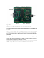
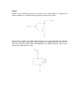
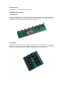
NETIOM-Link
User Manual
About This Manual
This manual provides a detailed description of the operation and features of Netiom-Link. It
assumes that the reader is familiar with network terminology and therefore does not give any
detailed descriptions of networks or their operation.
If you are not familiar with networking then it may help to read the “Network Terminology”
document.
PC based software is provided which provides a graphical interface to the programming
features of Netiom-Link. This manual makes reference to this software in the explanations for
the set up procedure.
It is not necessary to read the whole manual before setting up Netiom-Link as it is unlikely
that you will use all of its features. For small networks the Quick Start section should get you
up and running so that you can create a basic link.
If you encounter problems with the Quick Start then it likely that you have some sort of
problem with network addressing. If so refer to that section. The Introduction and Operation
section may also help with problem solving.
Details of how Netiom-Link establishes and controls the link are in the Appendices. This
information is provided for those who are interested in the internal workings of the link and for
a better understanding of its operation. It is not necessary to read or understand to this level
of detail to use the product.
Introduction
Netiom-Link is a network enabled Input / Output module. It is intended to work in pairs across
networks with the inputs of one Netiom-Link being repeated on the outputs of the second.
Serial data received at the port of one module will be sent out the serial port of the other
module.
Netiom-Link consists of:
16 Digital Inputs
16 Digital Outputs
1 Serial Port
1 Ethernet Port
Three LEDs are provided which show the status of the ethernet connection. A link is provided
to switch between active mode and programming mode.
Netiom-Link will work on both local networks and wide area networks such as the Internet.
To run Netiom-Link you will need:
A 12 Volt d.c. power supply.
A null modem serial lead (for programming).
An ethernet cable to connect to the network.
Operation
Netiom-Link has 3 LEDs which indicate the status of the ethernet connection.
Green indicates that Netiom-Link is connected to the network. When it is on it indicates that
the network connection is present but not necessarily that Netiom-Link is communicating with
the network.
Amber is the receive indication. This is normally on and switches off when data is received. In
normal operation this will flicker off every few seconds as it detects normal network polling.
Red is the transmit indication. This will switch off when data is transmitted from Netiom-Link. It
is normally on.
The programming link is used to switch Netiom-Link between active mode and programming
mode.
In active mode Netiom-Link will connect to the network and respond to ethernet messages. It
will not respond to any commands issued on the serial port.
In programming mode Netiom-Link will not access the network but it will accept commands
from the serial port. When the link is removed all network connections will be reset.
Quick Start
1. Place the programming link in position.
2. Connect the network to Netiom-Link with an ethernet cable.
3. Connect a 12 Volt d.c. power supply to the power terminals.
4. The LED’s should now be illuminated. The amber LED may flicker occasionally.
5. You may now want to verify the settings using the Netiom-Link Interface software.
6. Install and run the Netiom-Link Interface Software.
7. Select the PC comms port you will be using. This is on the General page.
8. Connect a null modem lead between the PC comms port and the Netiom-Link serial port.
9. Press the “Read From NETIOM-LINK” button. You can now review the settings.
10. The next step will depend on your network settings. If you have a DHCP server (typically
an ADSL router) proceed from section “With DHCP Server” otherwise go the section “Without
DHCP Server”.
With DHCP Server
11. Ensure that the following boxes are checked on the Data page:
“Get Address Automatically”
“Enable Client”
“Use Broadcast Address”
If are not checked then check them and download to Netiom-Link using the “Write To
NETIOM-LINK” button on the general page.
12. Remove the programming link. The red LED should now flicker once or twice.
13. Wait for about 5 seconds and replace the programming link.
14. Read the data back from Netiom-Link as before.
15. The assigned IP address will now be displayed on the Server page. If this reads 0.0.0.0
then the DHCP process has failed and it will be necessary to set up the IP address manually.
Follow the “Without DHCP Server” section instructions.
16. Repeat the procedure for the second module.
Without DHCP Server
17. You will need to set up the addressing manually. Uncheck the “Get Address
Automatically” box on the Data page of the Netiom-Link Interface software.
18. If there are a large number of devices on your network you will need to be assigned an IP
address from your network administrator. If there are only a few PCs you can determine their
address from a command prompt. Type in “ipconfig” and the settings will be returned. Make a
note of each one and choose an address close to the ones returned changing only the fourth
number. For example if your network is using 192.168.0.2 and 192.168.0.5 try using
192.168.0.6.
19. Enter the obtained number into the IP address boxes. You should be safe using
192.168.0.1 for the gateway address and 255.255.255.0 for the Submask.
20. Download the new data to Netiom-Link using the “Write To NETIOM-LINK” button on the
general page.
21 When the download is complete remove the programming link.
22.Repeat the procedure for the second module but you must use a different IP address from
the one used on the first module.
Interface Software
PC based software is provided to provide a graphical interface to programming Netiom-Link.
On the opening page there are controls for loading and sending data and a logging area
which will show a log of activity as well as any problems encountered.
The Data page is used to set all the necessary parameters for the Netiom-Link.
Data
Data can be written to Netiom-Link or read from it via the serial port at 19200 baud. Note that
the programming link must be in place before communications can be established with
Netiom-Link. The best way to use the program is to read data from Netiom-Link, modify it and
then write it back.
At start up the program will load a set of defaults from the file “DefaultConfig.txt”. If you need
a different set of defaults you can overwrite this file with your own values. If you have several
different configurations then these can be saved as separate files.
Before sending data to Netiom-Link the data is checked for any inconsistencies and will not
proceed if any are found. If problems are encountered a list is written to the logging window.
During the write operation to Netiom-Link all data is read back and compared with the data
sent. If there are any problems then they will be reported in the log window.
Setting The Address
In order to function properly on a network Netiom-Link needs know the following information:
IP Address
Gateway Address
Submask
Netiom-Link is able to collect this information automatically if the network has a DHCP server.
However if these addresses are obtained automatically they will be dynamic and can change
with time. This may cause an interruption to the link, however it should be restored
automatically.
To obtain an address automatically check the “Get Address Automatically” box. After you
download the data to Netiom-Link and remove the link Netiom-Link will attempt to obtain the
relevant information.
To set up the addresses manually uncheck the” Get Address Automatically” box and enter the
addresses in the appropriate edit boxes. Each box must contain a number in the range 0 to
255. The default values are:
IP Address: 192.168.0.6
Gateway Address: 192.168.0.1
Submask: 255.255.255.0
These values should be OK for small networks with only one or two computers and a gateway
router.
If you need to change them you will need to ascertain the values from the network. For local
networks there are three address ranges:
10.0.0.0 to 10.255.255.255
172.16.0.0 to 172.31.255.255
192.168.0.0 to 192.168.255.255
The best way to find free addresses is to log on to the gateway router as this will keep track of
all the attached devices. It will also show its own IP address which should be used as the
Gateway Address.
You can find the settings on any local PC running Windows by going to the command prompt
and typing “config”. This will return the IP Address of the PC, the Gateway Address and the
Submask. If you only have one PC and gateway router then use the last two values for the
Gateway Address and Submask and increment the last digit of the IP Address by 1.
Port Number
The port number is used as part of the network interface. This can be set anywhere in the
range 1 to 65535. However values below 1024 should be avoided as these are generally preallocated to well known services.
Both devices on a link must have the same port number otherwise they will not be able to
communicate with each other. If more than one pair of Netiom-Links are used on a network
then each pair should be allocated different port numbers.
Connections
The connections section defines how the link is established and maintained. At least one of
the pair must be enabled in client mode.
In client mode the Netiom-Link will periodically send out a network packet even if the link is
not established. Data will be transmitted whenever a change occurs on the inputs or when a
serial message is received. If there has been no change for a period defined by the Update
Period then a message will be transmitted as a heartbeat.
If client mode is not select messages are not transmitted until the link is established.
Messages will then be sent in the same way as in client mode.
When in client mode the Netiom-Link will need to know the IP address to connect to the other
end of the link. Two methods are available. If Use Broadcast Address is selected Netiom-Link
will transmit a broadcast to all devices on the network. The device at the other end will
recognise this message and return with a reply indicating its own IP address. The originating
device will then use this new IP address for further communication. Note that this method is
only suitable for local area networks as broadcasts are not allowed to transverse gateways.
The second method is to supply an IP address. In this case the originating Netiom-Link will
establish contact directly with the other end. This method must be used for wide area
networks such as the internet.
Serial Port
With the programming link in place the serial port always runs at 19200 baud.
In active mode you can specify the baud rate so that Netiom-Link can communicate with
external equipment. Netiom-Link can support baud rates in the range 2400 to 38400 baud.
Netiom-Link will store incoming serial data in a 64 byte working buffer until it deems that the
data string is complete. Once complete or the buffer is full the data is transmitted to the
remote Netiom-Link.
You can specify either a carriage return/line feed pair (CR/LF) indicates that the data is
complete or use a timed methology i.e. no data for a fixed period. If the latter is chosen then
the timeout value can be specified in the range 20mS to 20 seconds.
Note that it is important that both ends of the link have the same baud rate as there is limited
buffering within the Netiom-Links and congestion could cause data loss.
Watchdog
The watchdog facility can be used to monitor link activity. If this facility is enabled then output
1 will be activated when the link is established. Note that this will then remove the functionality
of Input 1.
MAC Address
This field shows the MAC address of the Netiom-Link. It is not possible to change this number
and is provided for information only.
Pings
Netiom-Link will respond to network pings. To ping Netiom-Link from a PC use the command
line ping followed by its IP address. For example:
ping 192.168.0.6
Hardware
Connections
The digital inputs and outputs are available via screw terminals or 10 way headers. The
headers also have power pins so that auxiliary modules can be powered directly from NetiomLink. Each of the headers has the same pin assignment regardless of whether they are inputs
or outputs. The following diagram shows the pin arrangement:
Digital Inputs
Each digital input is connected to a CMOS gate via a 100K resistor. It is pulled up to the
internal 5 Volt supply rail via a 10K resistor.
The input can be directly interfaced to TTL and CMOS outputs. The input voltage should not
exceed 5 Volts. In addition the inputs can use clean contacts referenced to 0 Volts or open
collector outputs again referenced to 0 Volts.
If the driving modules do not share the same power supply as Netiom-Link then it will be
necessary to common their 0 Volt lines.
The inputs are scanned with a timebase of 100mS. Thus the input signal must be present for
200mS in order to guarantee Netiom-Link seeing it.
With the input high or open circuit Netiom-Link will report it as a “1”, otherwise it will be
reported as a “0”.
Outputs
Outputs are open collector and can be used to drive relays solenoid LEDs etc. Optional LED
and relay modules are available which plug directly into the 10 way header.
Note that if these outputs are to drive inductive loads such as relays and motors then the load
must have some form of back EMF suppression fitted. IF SUPPRESSION IS NOT FITTED
THEN THE OUTPUT DEVICE WILL BE DAMAGED. The following diagram shows how to
interface the VIOM output to a relay.
Analogue Inputs
Analogue inputs are not used with Netiom-Link.
Hardware Accessories
Display Module
The display module consists of 8 LEDs which can be connected directly on to the Netiom-Link
controller. Connection is via a ribbon cable to the output header. If all 16 outputs are to be
displayed then two VIOM Display modules will be required.
Relay Module
The Relay module consists of 8 single pole change over relays which can be connected
directly on to the Netiom-Link controller. Connection is via a ribbon cable to the output
header. If all 16 outputs are to be used then two Relay modules will be required.