1
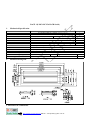
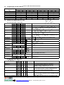
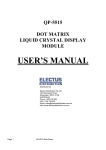
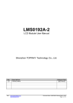
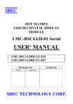
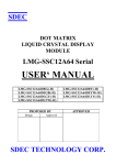
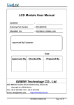
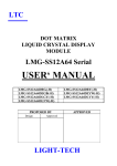
SDEC
DOT MATRIX
LIQUID CRYSTAL DISPLAY
MODULE
LMG-SSC25A32-GB Serial
USER‘ MANUAL
LMG-SSC25A32DRG-GB
LMG-SSC25A32DLGY-GB
PROPOSED BY
Design
LMG-SSC25A32DRY-GB
LMG-SSC25A32DLYY-GB
APPROVED
Approved
網站:http://handy.myweb.hinet.net EMAIL:[email protected]
SDEC TECHNOLOGY CORP.
CONTENTS
1.
2
3.
4.
5.
6.
7.
8.
9.
Mechanical Specification
Mechanical Diagram
Interface Pin Connections
Absolute Maximum Rating
Electrical Characteristics
Optical Characteristics
Optical Definitions
Char Display Address
Interface to MPU
9.1 Interface to Z-80 CPU
9.2 Interface to MC6800 CPU
9.3 Interface to 4-bit CPU ( HMCS43C )
9.4 Interface to HD6805 MP
PAGE
2
2
2
3
3
3
3
3
4
4
4
4
4
10. Timing Control
10.1 Write and Read Operation
10.2 Busy flag check timing
4
4
4
11.
12.
13.
14.
15.
16.
5
6
7
7
8
8
8
8
Initialization of LCM
Instruction Set
User Font Patterns
Icon RAM Data
Graph Display RAM Address
Software Example
16.1 8-bit operation ( 8 bits 2 lines )
16.2 4-bit operation ( 4 bits 2 lines )
17. Reliability Condition
18. Function Test & Inspection Criteria
19 Character Generator ROM Map
網站:http://handy.myweb.hinet.net EMAIL:[email protected]
9
9
10
PAGE 1 (LMG-SSC25A32-GB Serial)
1.
Mechanical Specification
ITEM
NUMBER OF CHARACTERS
CHARACTER FORMAT
MODULE DIMENSION
VIEWING DISPLAY AREA
ACTIVE DISPLAY AREA
DOT SIZE
DOT PITCH
LMG-SSC25A32DRG-GB
LMG-SSC25A32DRY-GB
LMG-SSC25A32DLGY-GB
LMG-SSC25A32DLYY-GB
LED Backlight Color
LED Backlight Input
Backlight Half-Lift Time
2.
STANDARD VALUE
16 CHARACTERS X 2 LINES (16*16 中文字)
16 X 16 DOTS
151.0 (W) X 40.0 (H) X 10.5 (T)
151.0 (W) X 40.0 (H) X 15.0 (T)
120.0 (W) X 23.0 (H)
107.49 (W) X 14.37 (H)
0.39 (W) X 0.42 (H)
0.42 (W) X 0.45 (H)
STN , Gray , 1/32 Duty , 6 O‘clock
STN , Yellow Green , 1/32 Duty , 6 O‘clock
STN , Gray , 1/32 Duty , 6 O‘clock , LED Backlight
STN , Yellow Green , 1/32 Duty , 6 O‘clock , LED Backlight
Yellow Green
DC +5V
V
300
50,000
Mechanical Diagram
3. Interface Pin Connections
網站:http://handy.myweb.hinet.net EMAIL:[email protected]
UNIT
--mm
mm
mm
mm
mm
mA
HR.
NO
1
2
3
4
5
6
7
8
SYMBOL
VSS
VDD
N.C
RS
R/W
E
DB0
DB1
LEVEL
-H/L
-H/L
H/L
H,H→L
H/L
H/L
FUNCTION
GND ( 0V)
DC +5V
N.C
Register select
Read/Write
Enable signal
Data Bit 0
Data Bit 1
NO
9
10
11
12
13
14
15
16
SYMBOL
DB2
DB3
DB4
DB5
DB6
DB7
A(+)
K(-)
LEVEL
H/L
H/L
H/L
H/L
H/L
H/L
DC +5V
0V
FUNCTION
Data Bit 2
Data Bit 3
Data Bit 4
Data Bit 5
Data Bit 6
Data Bit 7
LED Backlight +
LED Backlight -
PAGE 2 (LMG-SSC25A32-GB Serial)
4. Absolute Maximum Ratings
ITEM
OPERATING TEMPERATURE
STORAGE TEMPERATURE
INPUT VOLAGE
SUPPLY VOLTAGE FOR LOGIC
SUPPLY VOLTAGE FOR LCD
STATIC ELECTRICITY
SYMBOL
MIN.
TYPE
TOP
0
-TST
-10
-VI
VSS
-VDD-VSS
-5.0
VDD-VO
--Be sure that you are grounded when handing LCM.
MAX.
+50
+60
VDD
6.5
6.5
UNIT
℃
℃
V
V
V
5. Electrical Characteristics
ITEM
SUPPLY VOLTAGE FOR LOGIC
SYN
VDD-VSS
MIN.
4.5
----
TYPE
5.0
6.1
5.8
5.5
MAX.
5.5
----
UNIT
V
V
V
V
VIH
VIL
VOH
VOL
IDD
CONDITION
-Ta= 0 ℃
Ta= +25 ℃
Ta= +50 ℃
----VDD=+5V
SUPPLY VOLTAGE FOR LCD
VDD-VO
INPUT HIGH VOLTAGE
INPUT LOW VOLTAGE
OUTPUT HIGH VOLTAGE
OUTPUT LOW VOLTAGE
SUPPLY CURRENT
2.2
0
2.4
---
----4.5
VDD
0.6
-0.4
6.0
V
V
V
V
mA
SYM
θ
φ
CR
TON
TOFF
CONDITION
CR≧2
CR≧2
----
MIN.
-10
-30
----
TYPE
--5
180
100
MAX.
40
30
-230
150
UNIT
deg.
deg.
-mS
mS
6. Optical Characteristics
ITEM
VIEW ANGLE (V)
VIEW ANGLE (H)
CONTRAST RATIO
RESPONSE TIME
RESPONSE TIME
7. Optical Definitions
Response Time
Contrast Ration
View Angle
網站:http://handy.myweb.hinet.net EMAIL:[email protected]
8. Display Address
1
Line 1
Line 2
Line 3
Line 4
2
17
Line 1
Line 2
Line 3
Line 4
3
80H
90H
4
5
81H
91H
18
88H
98H
19
6
7
82H
92H
20
21
89H
99H
22
8AH
9AH
8
9
83H
93H
23
10
11
84H
94H
24
25
8BH
9BH
12
26
27
8CH
9CH
14
15
86H
96H
28
8DH
9DH
*A Ram Bank is 16 bits (2 bytes)
PAGE 3 (LMG-SSC25A32-GB Serial)
9. Interface to MPU
9.1
13
85H
95H
Interface to Z-80 CPU
9.2
Interface to MC6800 CPU
9.3 Interface to 4-bit CPU ( HMCS43C )
9.4
Interface to HD6805 MP
10. Timing Control
10.1 Write and Read Operation
網站:http://handy.myweb.hinet.net EMAIL:[email protected]
29
30
8EH
9EH
16
87H
97H
31
32
8FH
9FH
Write Operation
Read Operation
Item
Enable Cycle Time
Enable Pules Width ( High level )
Enable Rise/Fall Time
Address Set-Up Time ( RS,R/W,E )
Address Hole Time
Data Set-Up Time
Data Delay Time
Data Hold Time
Symbol
tCYCE
PWEH
tER,tEF
tAS
tAH
tDSW
tDDR
tDHR
Limit (Min.)
1200
140
-10
20
40
-20
Limit (Max.)
--25
---100
--
Unit
ns
ns
ns
ns
ns
ns
ns
ns
10.2 Busy flag check timing
Note : IR7, IR3 : Instruction 7th bit , 3rd bit ; AC3 : Address Counter 3rd bit.
PAGE 4 (LMG-SSC25A32-GB Serial)
11. Initialization of LCM
The LCM automatically initializes ( reset ) when power is turned on using the internal reset circuit. If the power supply
conditions for correctly operating of the internal reset circuit are not met, initialization by instruction is required. Use the
procedure is next page for initialization.
Internal Power Supply reset
4.5V
Vcc
0.2V
→
←
toff
trcc
←------→
(Note 1) 10 ms ≧ trcc ≧ 0.1 ms , toff ≧ 1 ms.
(Note 2) toff stipulates the time of power OFF for momentary power supply dip or when power supply cycles ON and OFF.
Item
Power supply rise time
Symbol
trcc
Test condition
--
Limit (Min.)
0.1
Limit (Max.)
10
網站:http://handy.myweb.hinet.net EMAIL:[email protected]
Unit
ms
Power supply off time
RS R/W
0
0
RS R/W
0
0
RS R/W
0
0
RS R/W
0
0
RS R/W
0
0
toff
--
1
--
8 bit Interface
4 bit Interface
Power On
↓
Wait time > 40 ms
↓
Function Set
DB7 DB6 DB5 DB4 DB3 DB2
0
0
1
1
X
0
↓
Wait time > 100μs
↓
Function Set
DB7 DB6 DB5 DB4 DB3 DB2
0
0
1
1
X
0
↓
Wait time > 37μs
↓
Display ON/OFF Control
DB7 DB6 DB5 DB4 DB3 DB2
0
0
0
0
1
D
↓
Wait time > 100μs
↓
Display Clear
DB7 DB6 DB5 DB4 DB3 DB2
0
0
0
0
0
0
↓
Wait time > 10ms
↓
Entry Mode Set
DB7 DB6 DB5 DB4 DB3 DB2
0
0
0
0
0
1
↓
Initialization End
Power On
↓
Wait time > 40 ms
↓
Function Set
DB7 DB6 DB5 DB4 DB3 DB2
0
0
1
1
X
X
↓
Wait time > 100μs
↓
Function Set
DB7 DB6 DB5 DB4 DB3 DB2
0
0
1
0
X
X
X
0
X
X
X
X
↓
Wait time > 100μs
↓
Display ON/OFF Control
DB7 DB6 DB5 DB4 DB3 DB2
0
0
0
0
X
X
1
D
C
B
X
X
↓
Wait time > 100μs
↓
Display Clear
DB7 DB6 DB5 DB4 DB3 DB2
0
0
0
0
X
X
0
0
0
1
X
X
↓
Wait time > 10ms
↓
Entry Mode Set
DB7 DB6 DB5 DB4 DB3 DB2
0
0
0
0
X
X
0
1
I/D
S
X
X
↓
Initialization End
DB1 DB0
X
X
RS R/W
0
0
DB1 DB0
X
X
RS R/W
0
0
0
0
DB1 DB0
C
B
RS R/W
0
0
0
0
DB1 DB0
0
1
RS R/W
0
0
0
0
DB1 DB0
I/D
S
RS R/W
0
0
0
0
ms
DB1 DB0
X
X
DB1 DB0
X
X
X
X
DB1 DB0
X
X
X
X
DB1 DB0
X
X
X
X
DB1 DB0
X
X
X
X
PAGE 5 (LMG-SSC25A32-GB Serial)
12. Instruction Set
Instruction Table: ( RE=0: Enable basic instruction. )
Instruction
Clear Display
Return Home
Instruction Code
Description
Ex.
Time
RS RW DB7 DB6 DB5 DB4 DB3 DB2 DB1 DB0
540KHz
0
0
0
0
0
0
0
0
0
1 Clear entire display and return the cursor to home 4.6ms
position ( address 0 ).
0
0
0
0
0
0
0
0
1
X Return cursor to the home position. Also returns the 4.6ms
display being shifted to the original position.
DDRAM contents remain unchanged.
網站:http://handy.myweb.hinet.net EMAIL:[email protected]
Entry Mode Set 0
0
0
0
0
0
0
1
I/D
S
Display
ON/OFF
control
Cursor or
Display shift
Function
Set
(Modify)
Set CGRAM
address
Set DDRAM
address
Read Busy flag
and address
0
0
0
0
0
0
1
D
C
B
0
0
0
0
0
1
X
X
0
0
0
0
1
DL
X
X
0
0
0
1
AC5 AC4 AC3 AC2 AC1 AC0 Set CGRAM address in address counter.
72μs
0
0
1
0
AC5 AC4 AC3 AC2 AC1 AC0 Set DDRAM address in address counter.
72μs
0
1
0μs
1
0
1
1
BF AC6 AC5 AC4 AC3 AC2 AC1 AC0 Whether during internal operation or not can be
known by reading BF. The contents of address
counter can also be read.
D7 D6 D5 D4 D3 D2 D1 D0 Write data into internal RAM.
(DDRAM/CGRAM/IRAM/GRAM)
D7 D6 D5 D4 D3 D2 D1 D0 Read data from internal RAM.
(DDRAM/CGRAM/IRAM/GRAM)
Write data to
RAM
Read data from
RAM
S/C R/L
X
0
RE
Sets cursor move direction and specifies display
shift. These operation are performed during data
rite/read. For normal operation.
I/D=1 : increment ; 0 :decrement ;
S=1 : accompanies display shift when data is
written, for normal operation, set to zero.
D=1: ON display ; 0:OFF display.
C=1: ON cursor ; 0: OFF cursor.
B=1: ON blink cursor ; 0: OFF blink cursor.
S/C=1: Display shift; 0:Cursor move. R/L=1: shift
to right; 0: shift to left.
DL=1: Interface is 8 bits. 0: Interface is 4 bits.
RE=0: Normal instruction .1: Extended instruction.
72μs
72μs
72μs
72μs
72μs
72μs
Instruction Table ( RE=1: Enable extension instruction. )
Instruction
Instruction Code
Description
RS RW DB7 DB6 DB5 DB4 DB3 DB2 DB1 DB0
Standby Mode
0
0
0
0
0
0
0
0
0
1
Start Row
Enable
Reverse Line
select
Sleep mode and
set GRAM page
Function
Set
(Modify)
Set Iram/Start
Row address
Set Graphic
RAM address
0
0
0
0
0
0
0
0
1
0
0
0
0
0
0
0
1
R1
Enter standby mode, only Icon areas display
Standby mode can be released by any other
instructions.
SR SR=1: Allow change start display Row.
SR=0: Disable start display Row change.
R0 Choice one of 4 line which data is reverse display.
0
0
0
0
0
0
1
SL
X
X
0
0
0
0
0
0
0
0
1
SL=0:Enter sleep mode.
1:Wake-up from sleep mode
0
1
DL X
1
G
0 DL=1: Interface is 8 bits. 0: Interface is 4 bits.
RE
RE=1: Extended instruction.0: Normal instruction.
G=1: Graphic display ON. 0: Graphic display OFF
1 AC5 AC4 AC3 AC2 AC1 AC0 SR=1: AC5 – AC0 is start Row.
SR=0: AC3 – AC0 is ICON RAM address.
AC6 AC5 AC4 AC3 AC2 AC1 AC0 Set GDRAM address in address counter. Execute
once set the address of display row (AC6-AC0).
0
0
0 AC3 AC2 AC1 AC0
Execute again set the address of display column
(AC3-AC0).
Ex.
Time
540KHz
72μs
72μs
72μs
72μs
72μs
72μs
72μs
PAGE 6 (LMG-SSC25A32-GB Serial)
13.
User Font Patterns ( CG RAM Character )
Character Code (DDRAM data)
B15 – B4
0
CGRAM Address
CGRAM data (High byte)
CGRAM data (Low byte)
B3 B2 B1 B0 B5 B4 B3 B2 B1 B0 D15 D14 D13 D12 D11 D10 D9 D8 D7 D6 D5 D4 D3 D2 D1 D0
X
00
X
00
0
0
0
0
0
1
0
0
0
0
0
1
0
網站:http://handy.myweb.hinet.net EMAIL:[email protected]
0
1
0
0
0
0
0
0
14.
X
01
X
01
0
0
0
1
0
1
0
0
0
0
0
1
0
0
0
1
0
0
0
0
0
0
1
0
1
1
1
1
0
0
0
1
0
0
0
1
0
0
0
0
0
0
1
1
0
1
0
0
0
0
1
1
1
1
1
1
1
1
1
0
0
1
0
0
0
1
0
0
0
1
0
1
0
0
0
0
1
0
0
0
0
1
0
1
0
1
0
1
0
0
0
1
0
0
0
0
1
0
0
0
0
1
1
0
0
1
0
1
0
0
0
1
1
1
1
1
1
1
1
0
0
1
1
1
1
0
0
1
0
0
0
1
0
0
0
0
1
0
0
0
1
0
0
0
1
0
1
0
0
0
0
1
0
0
0
0
1
0
0
0
1
0
0
1
1
0
1
0
0
0
0
1
1
1
1
1
1
1
1
0
1
0
1
0
0
0
1
0
0
0
0
1
0
0
0
0
1
0
0
0
1
0
1
1
0
1
0
0
1
0
0
1
0
0
0
0
1
0
0
0
1
1
0
0
1
1
1
1
1
0
0
1
1
1
1
1
1
1
1
0
1
1
0
1
0
0
0
0
1
0
0
1
0
0
0
0
0
0
0
0
1
1
1
0
0
0
0
0
0
0
0
0
0
0
0
0
0
0
0
0
1
1
1
1
0
0
0
0
0
0
0
0
0
0
0
0
0
0
0
0
0
0
0
0
0
0
1
0
0
0
0
1
1
1
1
1
1
1
0
0
0
0
0
1
0
0
1
0
0
0
0
1
0
1
0
1
0
1
0
0
0
0
1
0
0
1
0
1
0
0
0
1
1
1
1
1
1
1
0
0
0
0
1
1
1
1
1
1
1
0
0
0
0
0
1
0
0
0
0
0
0
1
0
0
1
0
1
0
1
0
0
0
1
1
1
1
1
0
0
0
0
1
0
1
0
0
1
0
0
0
0
0
0
0
1
0
0
0
0
0
0
1
1
0
0
0
1
0
0
0
0
1
1
1
1
1
1
1
0
0
0
1
1
1
1
1
1
1
1
0
0
0
1
0
0
0
1
0
0
0
1
0
0
0
0
0
1
0
0
0
0
0
0
1
0
1
0
0
0
0
1
0
0
1
0
0
1
0
0
0
0
1
1
1
1
1
1
1
0
0
1
0
1
0
0
0
1
0
1
0
0
0
0
0
1
0
0
0
0
0
1
0
1
1
1
0
1
0
1
0
0
0
1
1
1
1
1
0
0
0
1
1
0
0
1
0
1
0
0
0
0
0
0
0
1
0
0
0
0
0
1
1
0
1
0
0
1
1
1
0
0
0
0
0
1
0
0
0
0
0
1
1
1
0
1
1
0
0
0
0
0
0
0
0
1
0
0
0
0
0
1
1
1
1
0
0
0
0
0
0
0
0
0
0
0
0
0
0
0
0
Icon RAM Data
Icon RAM
Address
Icon RAM Data
AC3 AC2 AC1 AC0 D15
D14
D13
0
0
0
0
Seg0 Seg1 Seg2
0
0
0
1 Seg16 Seg17 Seg18
0
0
1
0 Seg32 Seg33 Seg34
0
0
1
1 Seg48 Seg49 Seg50
0
1
0
0 Seg64 Seg65 Seg66
0
1
0
1 Seg80 Seg81 Seg82
0
1
1
0 Seg96 Seg97 Seg98
0
1
1
1 Seg112 Seg113 Seg114
1
0
0
0 Seg128 Seg129 Seg130
1
0
0
1 Seg144 Seg145 Seg146
1
0
1
0 Seg160 Seg161 Seg162
1
0
1
1 Seg176 Seg177 Seg178
1
1
0
0 Seg192 Seg193 Seg194
1
1
0
1 Seg208 Seg209 Seg210
1
1
1
0 Seg224 Seg225 Seg226
1
1
1
1 Seg240 Seg241 Seg242
High Byte
D12
D11
Seg3 Seg4
Seg19 Seg20
Seg35 Seg36
Seg51 Seg52
Seg67 Seg68
Seg83 Seg84
Seg99 Seg100
Seg115 Seg116
Seg131 Seg132
Seg147 Seg148
Seg163 Seg164
Seg179 Seg180
Seg195 Seg196
Seg211 Seg212
Seg227 Seg228
Seg243 Seg244
D10
Seg5
Seg21
Seg37
Seg53
Seg69
Seg85
Seg101
Seg117
Seg133
Seg149
Seg165
Seg181
Seg197
Seg213
Seg229
Seg245
D9
Seg6
Seg22
Seg38
Seg54
Seg70
Seg86
Seg102
Seg118
Seg134
Seg150
Seg166
Seg182
Seg198
Seg214
Seg230
Seg246
D8
Seg7
Seg23
Seg39
Seg55
Seg71
Seg87
Seg103
Seg119
Seg135
Seg151
Seg167
Seg183
Seg199
Seg215
Seg231
Seg247
D7
Seg8
Seg24
Seg40
Seg56
Seg72
Seg88
Seg104
Seg120
Seg136
Seg152
Seg168
Seg184
Seg200
Seg216
Seg232
Seg248
D6
Seg9
Seg25
Seg41
Seg57
Seg73
Seg89
Seg105
Seg121
Seg137
Seg153
Seg169
Seg185
Seg201
Seg217
Seg233
Seg249
D5
Seg10
Seg26
Seg42
Seg58
Seg74
Seg90
Seg106
Seg122
Seg138
Seg154
Seg170
Seg186
Seg202
Seg218
Seg234
Seg250
Low Byte
D4
D3
Seg11 Seg12
Seg27 Seg28
Seg43 Seg44
Seg59 Seg60
Seg75 Seg76
Seg91 Seg92
Seg107 Seg108
Seg123 Seg124
Seg139 Seg140
Seg155 Seg156
Seg171 Seg172
Seg187 Seg188
Seg203 Seg204
Seg219 Seg220
Seg235 Seg236
Seg251 Seg252
網站:http://handy.myweb.hinet.net EMAIL:[email protected]
D2
Seg13
Seg29
Seg45
Seg61
Seg77
Seg93
Seg109
Seg125
Seg141
Seg157
Seg173
Seg189
Seg205
Seg221
Seg237
Seg253
D1
Seg14
Seg30
Seg46
Seg62
Seg78
Seg94
Seg110
Seg126
Seg142
Seg158
Seg174
Seg190
Seg206
Seg222
Seg238
Seg254
D0
Seg15
Seg31
Seg47
Seg63
Seg79
Seg95
Seg111
Seg127
Seg143
Seg159
Seg175
Seg191
Seg207
Seg223
Seg239
Seg255
PAGE 7 (LMG-SSC25A32-GB Serial)
15. Graph Display RAM Address
GDRAM Column
Address
0
1
2
:
61
62
63
D15
D15
D15
D15
D15
D15
0
→
→
→
:
→
→
→
D0
D0
D0
D15
D15
D15
D0
D0
D0
D15
D15
D15
GDRAM Row Address
1
----→ D0
D15 →
→ D0
D15 →
→ D0
D15 →
:
:
→ D0
D15 →
→ D0
D15 →
→ D0
D15 →
D0
D0
D0
D0
D0
D0
15
D15 → D0
D15 → D0
D15 → D0
:
D15 → D0
D15 → D0
D15 → D0
16. Software Example (BIG-5 Code)
16.1 8-bit operation ( 8 bits 2 lines )
Function
R R D D D D D D D D
S W 7 6 5 4 3 2 1 0
Display
Power on delay
Description
Function set
0 0 0 0 1 1 0 0 0 0
Display OFF
0 0 0 0 0 0 1 0 0 0
Initialization. No display appears.
Sets to 8-bit operation and selects 2-line display character font.
( Note: number of display lines and character fonts cannot be
change after this. )
Turn off display.
Display ON
0 0 0 0 0 0 1 1 1 0
Turn on display and cursor
Entry Mode
Set
0 0 0 0 0 0 0 1 1 0
Write data to
CG/DD RAM
Write data to
CG/DD RAM
Set DD RAM
1
1
1
1
0
Write data to
CG/DD RAM
Cursor or display
shift
Write data to
CG/DD RAM
Entry Mode
Set
Write data to
CG/DD RAM
Write data to
CG/DD RAM
Return Home
0
0
0
0
0
1
1
1
0
1
0
0
1
1
0
1
1
0
0
0
1
0
0
0
1
0
1
0
1
0
1
1
1
1
0
1
1
0
0
0
0 雄_
1
1 雄鐸
1
0 雄鐸
*
*
0 0 0
0 0 0
1 0 0
0 0 0
Set mode to increment the address by one and to shift the cursor to
the right, at the time of write, to the DD/CG RAM Display is not
shifted.
Write “雄”. Cursor incremented by one and shift to right.
Write “鐸” .
雄鐸
CR
0 0 1 0 0 x x 雄鐸
CR
*
雄鐸
*
CO., LTD.
0 0 0 0 1 1 1 雄鐸
CO., LTD.
鐸
1 1 1 1 0 0 0 ., LTD. x
*
*
0 0 0 0 0 1 0 雄鐸
CO., LTD.
Set RAM address so that the cursor is propositioned
at the head of the second line.
Write “C” , and “R”.
Shift only the cursor position to the left.
Write “O., LTD.” .
Set display mode shift at the time during writing operation.
Write “ x”. Cursor incremented by one and shift to
right. ( The display move to left. )
Write other characters.
Return both display and cursor to the original position ( Set
address to zero).
16.2 4-bit operation ( 4-bit, 1 line )
Function
RS R/ D7 D6 D5 D4
W
power on delay
Function set
0
0
0
0
1
0
Function set
0
0
0
0
0
0
0
0
1
0
0
0
Display ON/OFF Control
0
0
0
0
0
0
0
0
0
1
0
0
0
1
0
1
0
1
0
1
0
0
0
0
Write data to CG/DD RAM 1
0
1
0
1
1 雄_
Entry Mode Set
Display
Description
initialization. No display appears.
Sets to 4-bit operation. In this case, operation is
handled as 8-bits by initialization, and only this
instruction completes with one write.
Sets 4-bit operation and selects 1-line display character font
on and resetting is needed. ( number of display lines and
character fonts cannot be changed hence after ).
Turn on display and cursor.
Set mode to incremented the address by one and to shift the
cursor to the right, at the time of write. to the DD/CG RAM
display is not shifted.
Write “雄”. Cursor incremented by one and shift to right.
網站:http://handy.myweb.hinet.net EMAIL:[email protected]
1
1
1
0
0
0
0
1
1
1
0
1
1
1
1
0
0
1
same as 8-bit operation
PAGE 8 (LMG-SSC25A32-GB Serial)
17. Reliability Condition
TN Type
STN Type
Normal Temp.
Wide Temp.
Normal Temp.
Wide Temp.
Viewing
Horizontal Φ
±30°
±30°
±30°
±30°
Angle
Vertical Θ(㎜)
10°to 30°
10°to 30°
-10°to 40°
-10°to 40°
*
Operating Temperature
-10 to 70℃
-25 to 80℃
0 to 50℃
-20 to 70℃
*
Storage Temperature
-20 to 80℃
-35 to 90℃
-20 to 70℃
-30 to 80℃
High Temperature (Power Off)
240 Hours
240 Hours
240 Hours
240 Hours
@70℃
@90℃
@65℃
@75℃
Low Temperature (Power Off)
240 Hours
240 Hours
240 Hours
240 Hours
@-20℃
@-35℃
@-15℃
@-25℃
High Temperature (Power On)
240 Hours
240 Hours
240 Hours
240 Hours
@70℃
@80℃
@60℃
@70℃
Low Temperature (Power On)
240 Hours
240 Hours
240 Hours
240 Hours
@-10℃
@-25℃
@-10℃
@-20℃
High Temperature & High Humidity
55℃/90%RH
75℃/90%RH
45℃/90%RH
65℃/90%RH
240 Hours
240 Hours
240 Hours
240 Hours
Thermal Shock
C
A
60min@-20℃
60min@-35℃
60min@-20℃
60min@-30℃
5 Cycle
B
B
5min@25℃
5min@25℃
5min@25℃
5min@25℃
A
C
60min@70℃
60min@90℃
60min@70℃
60min@80℃
Expected Lift
50,000 Hours
50,000 Hours
50,000 Hours
50,000 Hours
*
Wide temp. version may not available for some products, Please consult our sales engineer or respresentative.
18. Functional Test & Inspection Criteria
18.1 Sample plan
Sample plan according to MIL-STD-105D level 2, and acceptance/rejection criteria is.
Base on :
Major defect : AQL 0.65
Minor defect : AQL 2.5
18.2 Inspection condition
Viewing distance for cosmetic inspection is 30cm with bare eyes, and under an environment of
800 lus (20W) light intensity. All direction for inspecting the sample should be within 45°
against perpendicular line.
18.3 Definition of Inspection Zone in LCD
A
B
Zone A :
Zone B :
Zone C :
Note :
C
Character / Digit area
Viewing area except Zone A ( Zone A + Zone B = minimum Viewing area )
Outside viewing area ( invisible area after assembly in customer’s product )
As a general rule, visual defects in Zone C are permissible, when it is no trouble for
quality and assembly of customer’s product.
18.4 Major Defect
All functional defects such as open ( or missing segment ), short, contrast differential, excess
power consumption, smearing, leakage, etc. and overall outline dimension beyond the drawing.
Are classified as major defects.
網站:http://handy.myweb.hinet.net EMAIL:[email protected]
PAGE 9 (LMG-SSC25A32-GB Serial)
18.5Minor Defect
Except the Major defects above, all cosmetic defects are classified as minor defects.
Item No.
1.
2.
3.
4.
Item to be Inspected
Spot defect
( Defects in spot from )
Inspection Standard
Classification of defects
Acceptable Qty
Minor
A
B
C
Φ≦0.15
Acceptable ( clutering of Acceptable
spot not allowed )
0.15≦Φ≦0.20
1
2
0.20≦Φ≦0.25
0
1
Φ>0.25
0
0
Remarks : for dark/white spot, size Φ is defined as
Φ=1/2(X+Y)
Line defect ( Defects in
Size (mm)
Acceptable Qty
Minor
line form )
L
W
Zone
Length
Width
A
B
C
AccepW≦0.02
AccepAcceptable
table
table
L≦3.0
W≦0.03
2
L>2.5
W≦0.03
0
L≦3.0
0.03<W≦0.05
2
L>2.5
0.03<W≦0.05
0
W>0.05
Counted as spot defect
( Follows item 18.5.1 )
Remarks: The total of spot defect and line defect
shall not exceed four.
Orientation defect
Not allowed inside viewing area ( Zone A or Zone B )
Minor
( such as misalignment
of L/C)
Polarizing
18.5.4.1 Polarizer Position
Minor
1. Shifting in Position Should not exceed the
glass outline dimension.
2. Incomplete covering of the viewing area due to
Shifting is not allowed.
18.5.4.2 Seratches, bubble or dent on Glass/
Polarizer/Reflector, Bubble between
Polarizer & Reflector/Glass:
Size (mm)
Acceptable Qty
Zone
A
B
C
AccepΦ≦0.20
Acceptable
table
0.20<Φ≦0.50
3
0.50<Φ≦1.00
2
Φ>1.00
0
Zone size (mm)
19. Character Generator ROM Map
High 4-bit 0
0
1
►
1
◄
2
☻
↕
3
♥
‼
4
♦
¶
5
♣
§
6
♠
▄
Low 4-bit
7
8
↕
↑
9
○
↓
A
○
→
B
♂
←
網站:http://handy.myweb.hinet.net EMAIL:[email protected]
C
♀
∟
D
♪
↔
E
♫
▲
F
☼
▼
2
3
4
5
6
7
0
@
P
‘
p
!
1
A
Q
a
q
“
2
B
R
b
r
#
3
C
S
c
s
$
4
D
T
d
t
%
5
E
U
e
u
&
6
F
V
f
v
‘
7
G
W
g
w
(
8
H
X
h
x
)
9
I
Y
i
y
*
:
J
Z
j
z
+
;
K
〔
k
{
,
<
L
l
|
-
=
M
〕
m
}
.
>
N
︿
n
∼
?
O
o
△
字型碼 , 前 127 碼為標準 ASCII 碼 , 在中文為半形 , 中文碼由 A1A1 開始 , 共 8192 字 , 編
碼方式為 GB 碼.
PAGE 10 (LMG-SSC25A32-GB Serial)
SDEC
SDEC TECHNOLOGY CORP.
網站:http://handy.myweb.hinet.net EMAIL:[email protected]
10F, No. 100, Shing De Rd., San Chung City 241,
Taipei Hsien, Taiwan R.O.C.
TEL: 886-2-2999-2512
886-2-8512-1288
FAX:886-2-2999-2510
886-2-8512-2828
EMAIL:[email protected]
[email protected]
http://www.sdec.com.tw
網站:http://handy.myweb.hinet.net EMAIL:[email protected]