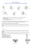
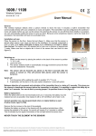
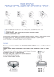
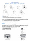
1
Social Alarm Management System 7 Professional CRS-LMS7-PRF | 970.130f | F.01U.173.315 | V1.6 | 2014.10 en User Manual Social Alarm Management System 7 Professional Table of Contents | en 3 Table of Contents 1 LMS 7 Professional - The concept 7 1.1 Concept description 7 1.2 Co-operation partner feature 8 2 System description 9 2.1 Call procedure 9 2.2 Windows buttons 10 2.3 The most common call triggers 10 2.4 Logging in to the alarm system 11 3 User interface 12 3.1 Emergency call template 12 3.2 Information field 12 3.3 Note field 12 3.4 Document bar 12 3.5 Display field 13 3.6 Status bar 14 3.7 Additional applications 14 3.8 Call handling 14 3.9 Device functions 15 3.10 Dial pad 16 3.11 Alarm list 16 4 Buttons in the document bar 18 4.1 Reason/actions 18 4.2 Alarm summary 18 4.3 Organisation 19 4.4 Call history 19 4.5 Additional data 20 4.6 Subscriber notes 21 4.7 Map 22 4.8 Key management 23 4.9 Device data 24 4.10 Device history 25 5 Call handling 26 5.1 Keyboard operation 26 5.2 Call indication 27 5.3 Accepting an alarm 27 5.4 Forwarding to all alarm handling workstations 28 5.5 Forwarding to a particular operator 28 5.6 Parking a call 28 5.7 Handling calls in parallel 29 5.8 Terminating a call 29 5.9 Full-duplex voice/half-duplex voice 29 Bosch Security Systems User Manual 970.130f | F.01U.173.315 | V1.6 | 2014.10 4 en | Table of Contents Social Alarm Management System 7 Professional 5.10 Handling of Incoming and Outbound phone calls 30 5.11 Handling of test calls 30 5.12 Timeout for social alarms and phone calls 30 6 Device functions 31 6.1 Special buttons 31 6.2 Additional applications 31 7 Windows menu in Alarm handling 34 7.1 System 34 7.1.1 User 36 7.1.2 Help 36 8 Data administration 37 8.1 View 39 8.2 Search filter 39 8.3 Paging/sorting/printing 40 9 Subscriber data 41 9.1 Displaying 41 9.1.1 Subscriber core data 42 9.1.2 Additional data 44 9.1.3 Note 45 9.1.4 Location 46 9.1.5 History 46 9.1.6 Keys 48 9.1.7 File 49 9.2 Creating new subscriber data records 50 10 Device data 51 10.1 Displaying 51 10.1.1 Device core data 52 10.1.2 History 53 10.1.3 Programming 55 10.1.4 RF detector 60 10.2 Creating new device data records 61 10.3 Analysis 62 11 Contact handling 63 11.1 Creating a new contact 63 11.2 Modifying and deleting a contact 64 11.3 Assigning a contact 64 11.4 Additional functionality during assigning a contact: changing the contact details 64 11.5 Additional functionality during assigning a contact: creating a new contact 64 11.6 Assigning a subscriber as contact 64 11.7 Deleting a contact already assigned 64 970.130f | F.01U.173.315 | V1.6 | 2014.10 User Manual Bosch Security Systems Social Alarm Management System 7 Professional Table of Contents | en 5 12 History 65 12.1 Current call events 67 12.2 Alarm events 67 12.3 Key events 68 12.4 Reminder events 68 12.5 Warning events 69 12.6 Administration events 69 12.7 System events 70 12.8 All events 70 13 Administration 71 13.1 User list 72 13.2 User name 72 13.3 New user 73 13.4 Role list 73 13.4.1 What is a role? 74 13.4.2 Modifying a role 75 13.4.3 Deleting a role 76 13.5 New role 76 13.5.1 Pre-defined rights at time of delivery 76 13.5.2 Creating a new role 77 13.6 Call filtering / balancing 77 13.6.1 Call balancing 77 13.6.2 Call filtering by events 78 13.6.3 Call filtering by organizations 79 13.6.4 Call filtering / balancing priority and check 79 13.7 Call forwarding 80 13.8 Keysafe list 81 13.9 Subscriber 81 13.10 Keysafe management 82 13.11 Additional data 83 13.11.1 New header 84 13.11.2 Drop-down list 85 13.11.3 Link text 86 13.12 Summary document 87 13.13 Events 88 13.14 Event groups 89 13.15 Map 89 13.16 Actions 90 13.16.1 Append actions 90 13.16.2 Delete actions 90 13.17 Reason 91 13.18 Link phone-workstation 92 13.18.1 Headset configuration 92 13.18.2 System phone configuration 92 13.19 Scheduler 93 13.20 Mandatory field 94 13.21 Co-operation partner list 95 13.21.1 Adding a co-operation partner 96 Bosch Security Systems User Manual 970.130f | F.01U.173.315 | V1.6 | 2014.10 6 en | Table of Contents Social Alarm Management System 7 Professional 13.21.2 Co-operation partner management 96 13.22 Subscriber status 97 13.23 Device template 98 13.24 Import/export template 99 13.25 Deleting history 99 14 Verification 100 14.1 Subscriber data 101 14.2 Additional data 102 14.3 Device data 103 14.4 Subscriber data list 104 14.5 Additional data list 104 14.6 Device data list 104 15 Password and logout 105 15.1 Changing a password 105 15.2 Logout 105 16 Error messages 106 16.1 No data received 106 16.2 PTU failure 106 16.3 Line failure 106 16.4 Database error 107 16.5 PBX middleware link error or PBX middleware CAP link error 107 16.6 PBX out of service 107 16.7 No server 108 16.8 SIP registration 108 16.9 Lost IP call connection 108 16.10 Exclamation mark in alarm list 108 17 Technical Recommendations 109 Index 110 970.130f | F.01U.173.315 | V1.6 | 2014.10 User Manual Bosch Security Systems Social Alarm Management System 7 Professional 1 LMS 7 Professional - The concept | en 7 LMS 7 Professional - The concept The Social Alarm Management System 7 Professional (LMS 7 Professional) from Bosch provides an innovative and effective system for conveniently and intuitively dealing with all administration activities associated with social alarms. The co-operation partner feature of the LMS 7 Professional allows many organisations to be linked. It enables the LMS 7 Professional operator to extend his field of operation and to increase turnover, for instance by collaborating with other social alarm providers that do not run their own call centres. Flexibility in data administration permits organisations to enter their own data in the system. Reliable protection of own data is guaranteed. The organisation benefits from improved functionality without having to invest in its own call centre. 1.1 Concept description 1. LMS 7 Professional call centre Alarms are handled centrally in the LMS 7 Professional call centre. 2. Call centre data administrator The call centre data administrator can enter, modify and delete subscriber and device data. Reports and statistics can also be created. You can define whether data administrators are able to view all data including that of organisations, or only own data. 3. Call centre system administrator The system administrator defines the LMS 7 Professional structure and processes, and controls access rights. 4. Operators Call centre operators receive and process emergency and service calls. Bosch Security Systems User Manual 970.130f | F.01U.173.315 | V1.6 | 2014.10 8 en | LMS 7 Professional - The concept 5. Social Alarm Management System 7 Professional Data exchange All data administrators access the database in the call centre. Modifications to data records are activated immediately and logged. The LMS 7 Professional operator can restrict modification rights for organisations. The operator can also verify organisations' data and makes the final decision to accept or reject modifications. 6. Organisations Data administrators for individual organisations can enter, modify and delete subscriber and device data. Reports and statistics can also be created here. According to the filtering settings, operators from different organisations can view and access their own data as well as data from other organisations. 1.2 Co-operation partner feature The call centre (1) receives emergency and service calls from subscribers. According to the organisation that he belongs to and the call filtering settings, the operators in the call centre (4) will see the calls and be able to accept them. Depending on the organisation (6) to which the subscriber has been assigned, the operator's alarm handling workstation displays the welcome text for the corresponding partner. The LMS 7 Professional call centre's (3) system administrator administers access rights and rights for individual data administrators and operators. Data administrators from the collaborating organisations have access to their data and, according to the settings, to the data of other organisations. Reports and statistics are displayed accordingly. 970.130f | F.01U.173.315 | V1.6 | 2014.10 User Manual Bosch Security Systems Social Alarm Management System 7 Professional 2 System description | en 9 System description The LMS 7 Professional has a modular structure and contains the following components: – PSTN lines: serves to connect the call centre to the public telephone network and to transfer calls within the call centre. – Line Units 1223 (LU1223): receives data telegrams from Carephones and forwards – CTI server (Computer Telephony Integration): contains the database of subscriber and protocol information to the CTI server. device data and co-ordinates all alarm events within the system. – Administration workstations: these are used for the administration of subscribers, devices and users. – Alarm handling workstations: used to accept and process incoming alarms. The information required for handling alarms is displayed. Administration activities according to the item above can also be performed from the alarm handling workstations. A workstation can be used with a headset or with a telephone. – Telephone system (optional): serves to connect the call centre to the public telephone network and the internal phones within the call centre. – The SIP option enables RBIP/SIP support, the LMS 7 can receive calls from the analog or emulated network and also calls issued from a Carephone equipped with an IP Module. – The Mobile Security / GSM Module option includes the integrated support of the Doro Secure IP protocol, for reception of alarms from Doro Secure phones, as well as online map material. This option also supports reception of calls from a GSM Module. It is possible to receive calls from various Mobile Security devices and to locate subscribers for fast help. The SMS modem allows support of SMS protocols as well as sending and receiving SMS from mobile phones. 2.1 Call procedure An alarm is triggered at a device, e.g. a Carephone, an RF pendant or another sensor at the subscriber's property. The alarm is forwarded via the public telephone network, and arrives at the CTI server after evaluation of the call protocol by the LU1223. It is also optionally possible to receive alarm calls from IP Carephones through the internet or via the GSM network from Carephones equipped with a GSM Module or from MobSec devices via GPRS or SMS. The CTI server sends the alarm to the connected alarm handling workstations via LAN (Local Area Network). If an operator accepts the alarm, the CTI server activates the alarm handling and a speak/listen connection is established to the subscriber via an headset or optionally via an operator telephone. The operator can park the call, forward it internally and initiate the necessary actions. Bosch Security Systems User Manual 970.130f | F.01U.173.315 | V1.6 | 2014.10 10 2.2 en | System description Social Alarm Management System 7 Professional Windows buttons Option buttons allow you to select just one option from a list of options: Checkboxes present you with options; you can select one or more options: Clicking on a button triggers the action linked to the button: List boxes display options, from which you can select only one: With dial buttons and highlighted phone numbers, you can call phone numbers: 2.3 The most common call triggers Emergency call button Emergency call triggered by pressing the emergency call button on the Carephone. RF detector Emergency call triggered by using an RF pendant connected to a Carephone. Service call Subscriber wishes to make use of a service. Logout The subscriber wishes to leave the house and provide notification of this. Login The subscriber has returned home and wishes to provide notification of this. Activity monitor The subscriber has not activated the daily button despite having been requested to do so by the Carephone. 970.130f | F.01U.173.315 | V1.6 | 2014.10 User Manual Bosch Security Systems Social Alarm Management System 7 Professional 2.4 System description | en 11 Logging in to the alarm system The symbol for alarm handling appears on your alarm handling workstation screen. To start the application, double-click the icon. A window opens, in which you can select the CTI server on which alarm handling is running. – A predefined CTI Server can be defined as a parameter for the program link on the alarm client desktop. – If no CTI servers are found, you can enter the IP address or the name of the server here. – The login window then appears. Log in with your user name and password. The alarm handling window is displayed. The status bar appears in the lower section of the screen; this contains the user name, alarm handling workstation name and the name of the CTI server. The appearance of this window depends on the option used. The following example is without CTI option: Contact your system administrator if the login attempt was unsuccessful. Bosch Security Systems User Manual 970.130f | F.01U.173.315 | V1.6 | 2014.10 12 en | User interface Social Alarm Management System 7 Professional 3 User interface 3.1 Emergency call template 3.2 Information field (1) The information field contains basic information about the subscriber or alarm event, as well as the call trigger (e.g. emergency call button). Optionally, information related to the location code will appear in this field. 3.3 Note/SMS field (2) You can view the last note entered in the note field. In case of unsupported SMS protocols, the SMS content is shown beside the note field on the right side. 3.4 Document bar (3) You can use the buttons to switch to the information contained in the lower display field. 970.130f | F.01U.173.315 | V1.6 | 2014.10 User Manual Bosch Security Systems Social Alarm Management System 7 Professional User interface | en 13 Note Discrepancies between the alarm and the database are shown here (e.g. incoming alarm from a Carephone not listed in the database). This button is only visible when entries are present. Reason/Actions The reason for a call (e.g. subscriber fallen) and the action taken (e.g. ambulance informed) is documented here. Alarm summary This function allows showing the most important information. The five information items by default are: – Absence, – History – Gender, – Subscriber status – Subscriber modification. Organisation This contains the welcome text for the corresponding organisation. Call history The history of the calls, as well as other events such as subscriber data modifications, reasons for calls and actions implemented are displayed here. Additional data Additional subscriber data recorded in the system is displayed here. Subscriber notes You can call up previous notes and add new notes here. A history of the notes is displayed. This button is highlighted in red if this is indicated accordingly under Administration. Map The map indicates directions to the subscriber. You can display a map extract of the subscriber's neighbourhood. Key management The subscriber's house keys can be checked in and checked out. This button is only visible if key management has been activated. Device data Device data for a device for which the alarm has been activated is displayed here. This button is highlighted in red if this is indicated accordingly under Administration. Device history History of the last alarms for this device. 3.5 Display field (4) The display field contains information assigned to the individual buttons in the document bar. The design and arrangement is dependent on the buttons selected. Bosch Security Systems User Manual 970.130f | F.01U.173.315 | V1.6 | 2014.10 14 3.6 en | User interface Social Alarm Management System 7 Professional Status bar (5) The following information is displayed in the status bar: – User name – Name of the handling workstation – Extension number of the system phone, in case of an activated CTI option. – Name of the CTI server or information if the connection to the server is interrupted. In case of Carephones connected through IP, the following information is also displayed: 3.7 – Extension number – Status of the SIP registration Additional applications (6) These buttons can be used to start additional applications. There are three default buttons: Print alarm, Display operating instructions and Call up data administration (upper row, left to right). The other 3 buttons can be configured to start external applications. Therefore the icon and the tool tip can be different. 3.8 Call handling (7) Call handling is active only during incoming, outgoing calls, and alarm calls. Calls can be accepted, terminated, sent back to all alarm handling workstations and forwarded to a particular operator. The following buttons are available: Terminate repeated emergency call Some Carephones support the option to send repeated emergency calls. Click this button to close the alarm completely. Terminate call The speaking connection is ended but the alarm remains active for further handling. Close alarm The alarm is closed. An alarm can only be closed once a reason and at least one action have been selected. 970.130f | F.01U.173.315 | V1.6 | 2014.10 User Manual Bosch Security Systems Social Alarm Management System 7 Professional User interface | en 15 Full-duplex/half-duplex voice Depending on its features, the Carephone can switch between full-duplex and half-duplex. Forward The alarm is sent back to all alarm handling workstations. Forward to/Park The alarm is forwarded to a particular operator. When you click this button, a list box with all the active operators appears, giving you also the possibility to park the call without audio, option "park". Volume You can adjust the volume of the Carephone from soft, to medium, to loud. With protocols ANT and RB2000, the appearance is the following: With other protocols (including Geocare MobSec devices), the volume setting buttons will have the following appearance: You can adjust the volume settings of the headset microphone and loudspeakers with the following sliders: These sliders appear for all protocols but do not appear in case of an activated CTI option. Talk button Click the talk button when in half-duplex mode. To switch from listening to speaking, hold the button down while speaking. The button is greyed out during full-duplex mode. 3.9 Device functions (8) The window contains different numbers of special buttons, depending on the type of device, for triggering special functions. The two upper buttons are deactivated within LMS 7 Professional. For further information about device functions, see Section 6 Device functions, page 31. Bosch Security Systems User Manual 970.130f | F.01U.173.315 | V1.6 | 2014.10 16 en | User interface 3.10 Social Alarm Management System 7 Professional Dial pad (8) The dial pad supports following functionality: – Creation of DTMF tones: Clicking on the number buttons (1-9, *, #) during an active phone call creates the corresponding DTMF tones. – Preparation of an outgoing phone call Enter the phone number into the text box or click the number buttons. Clicking on the pick-up button creates an outgoing call event in the upper alarm list. Double-clicking on this call event establishes the call. 3.11 Alarm list (9) Incoming emergency and service calls, and outgoing calls are displayed in the alarm list. The alarm list is split into two sections: – The upper section contains calls with an active speak/listening connection. – The lower section contains alarms without an active speak/listening connection. You can derive the following information from an incoming alarm: 1. Time elapsed in seconds since the alarm was received in the system 2. Call trigger 3. Subscriber 4. Organisation associated with subscriber 970.130f | F.01U.173.315 | V1.6 | 2014.10 User Manual Bosch Security Systems Social Alarm Management System 7 Professional User interface | en 17 If the call is accepted by an operator, the subscriber field will be a drop-down list if more than one subscriber is assigned to the device. It is possible to select another subscriber. In this case all data related to the other subscriber will be visible. All related data are changed and are specific to the subscriber. Therefore, all documents in the alarm client will be changed. The following symbols will help you recognise the status of an alarm: Incoming alarm: There is no symbol in front of the alarm. Alarm being handled: If an operator accepts an alarm by double-clicking it, a tick appears in the operator's alarm handling workstation. The active call is highlighted in light blue. The alarm appears in grey in all other alarm handling workstations for 2 seconds before it is deleted from the alarm list. Alarm forwarded to all alarm handling workstations: If the alarm was forwarded to all alarm handling workstations, an arrow appears next to the alarm. The counter resets to 0 when an alarm is forwarded. The alarm is highlighted in yellow during data communication for remote programming or remote query. Simulated alarms appear in italics. Alarm forwarded to a particular operator: If the alarm was forwarded, an arrow with a tick appears next to the alarm. The same symbol appears if the call was parked. Bosch Security Systems User Manual 970.130f | F.01U.173.315 | V1.6 | 2014.10 18 en | Buttons in the document bar Social Alarm Management System 7 Professional 4 Buttons in the document bar 4.1 Reason/actions An alarm can only be closed completely once a reason and at least one action have been entered – otherwise the call is parked. Select the Reasons/Actions button in the document bar. A number of reasons and actions are listed: You can enter your own actions in the text window below Actions. Select the appropriate reason and one or more actions by clicking the text. Use the text window to enter an action that does not appear in the list. 1. You can enter your own action text in the text window. 2. Click the symbol in front of the text window to confirm the entry. You can cancel a selected action by clicking the highlighted action text or the tick in the checkbox. In case of text created, hit the save button. 4.2 Alarm summary You can choose to make the Alarm summary visible by configuration in the administration menu, and set its place in the alarm summary box (left, right or centre). Additional data can be added, and the appearance depends on its configuration under Additional data. What is modified in the menu Additional data has impact on the menu summary document and on the alarm summary itself. 970.130f | F.01U.173.315 | V1.6 | 2014.10 User Manual Bosch Security Systems Social Alarm Management System 7 Professional 4.3 Buttons in the document bar | en 19 Organisation The welcome text for the organisations is stored here. The text can be freely configured by the system administrator; see Section 13.21.1 Adding a co-operation partner, page 96. In the document bar, click the Organisation button. The information for the corresponding organisation is displayed; this will be used to welcome the subscriber. 4.4 Call history The call history contains events pertaining to the current subscriber, only if the subscriber is assigned to a device. Click the Call history button in the document bar. The call history consists of a table with the following information: – Date and time – Device number – Call trigger – Name – Actions initiated You can sort the contents of the individual columns in ascending or descending order (e.g. according to call trigger) by clicking the dark table header. To display details on a particular event, click the required date. The alarm details will then be shown in the display field. You can append actions if necessary, by entering the text in the text field Bosch Security Systems click Append action. User Manual 970.130f | F.01U.173.315 | V1.6 | 2014.10 20 en | Buttons in the document bar Social Alarm Management System 7 Professional Use the Previous and Next buttons to view the details on the previous/next alarm. You can return to the call history overview by clicking Back. 4.5 Additional data Additional data stored on the subscriber in the LMS 7 Professional is displayed here. To view the subscriber data, click the Subscriber data button in the document bar. 970.130f | F.01U.173.315 | V1.6 | 2014.10 User Manual Bosch Security Systems Social Alarm Management System 7 Professional Buttons in the document bar | en 21 If an unknown subscriber or a subscriber who has not been assigned to a device calls, no subscriber data is available. Subscriber data can only be modified, deleted or created in Data administration with the appropriate rights; see Section 9 Subscriber data, page 41. 4.6 Subscriber notes You can make notes on the corresponding subscriber here. The notes can be edited during an alarm. The last subscriber note is displayed in the information field. To create a note, click Subscriber note in the document bar to create a note. You can add a new note. Click Save changes. You can view the subscriber note history in the lower section of the display field. New subscriber note You can add a new note by entering new text in the text window and subsequently clicking Save changes. Logout interval - Away reminder Click the Away reminder checkbox to indicate and generate a reminder in the system that the subscriber has signed out. You have an option to enter manually the time period in the adjacent date fields. You can select duration in the drop-down list, the time period will be automatically updated. Press the Save button. Bosch Security Systems User Manual 970.130f | F.01U.173.315 | V1.6 | 2014.10 22 en | Buttons in the document bar Social Alarm Management System 7 Professional The time period is visible in the lower part alarm list, as Away overdue. It can be ticked and you will get access to the subscriber data. The away reminder can be removed when the subscriber is back. Otherwise, the alarm is active and an action has to be taken (e.g. call the subscriber). The away reminder appears as a stand-alone event. Follow up You can select duration in the drop-down list, the time period will be automatically updated. You have an option to enter manually the time period in the adjacent date and time fields. You can save your choice with Start follow up. It then appears in pending follow-up. The follow-up and its reminder appear as the same event that is reactivated. It allows the user to clear his alarm list, without forgetting to perform an action. Example: A subscriber is calling, and asking for a doctor in an hour. The follow-up allows delaying an action without keeping an alarm active. Highlighting a note Clicking the Note marked checkbox highlights the button in red in the document bar. This is useful for important notes. Subscriber notes can also be edited under Data administration; see Section 9.1.3 Note, page 45. 4.7 Map To view the location of the calling subscriber's neighbourhood, click the Map button in the document bar. A description of the location for the subscriber entered is displayed. The map can be edited under Data administration; see Section 9.1.4 Location, page 46. 970.130f | F.01U.173.315 | V1.6 | 2014.10 User Manual Bosch Security Systems Social Alarm Management System 7 Professional 4.8 Buttons in the document bar | en 23 Key management This button is only displayed if key management has been activated for this subscriber. To view key management, click the Key management button in the document bar. The key management status is displayed: – Key checked in – Key checked out – Name of the safe into which the key has been checked – Checkout date and time Checking in key Click the Check in button. The key is now registered in the system as checked in. The information Key given to is also stored in the event history. Checking out a key In the text field, enter the name of the person to whom you wish to give the key and then click the Check out button. Bosch Security Systems User Manual 970.130f | F.01U.173.315 | V1.6 | 2014.10 24 4.9 en | Buttons in the document bar Social Alarm Management System 7 Professional Device data To view device data, 1. click the Device data button in the document bar. You can view all the information for a device here, and add notes. To do this, click the Note button and enter the text in the text field. Click Save changes. All the notes are displayed in the lower list, according to date. RF detector Click RF detector to view all connected peripheral devices. 970.130f | F.01U.173.315 | V1.6 | 2014.10 User Manual Bosch Security Systems Social Alarm Management System 7 Professional 4.10 Buttons in the document bar | en 25 Device history To view the device history, click the Device history button in the document bar. The device history consists of a table with the following information: Date and time, device and subscriber name. You can sort the contents of the individual columns in ascending or descending order (e.g. according to date and time) by clicking the dark table header. Details To view device history details, click the required date. The details then appear in a display field. The user can listen to the recorded conversations by clicking on the link. A voice recording file will open. Bosch Security Systems User Manual 970.130f | F.01U.173.315 | V1.6 | 2014.10 26 en | Call handling Social Alarm Management System 7 Professional 5 Call handling 5.1 Keyboard operation The keyboard functions are always only related to the active alarm in the LMS 7. You cannot switch backwards and forwards between individual calls using the keyboard functions. General Key Function Ctrl + Tab Steps forward through the document bar Accepting a call Key Function F1 Online Help F2 Accept the uppermost call with a speak/listening connection F3 Accept the uppermost alarm without a speak/listening connection Speaking to the subscriber Keys F6, F7 and F8 control the volume at the subscriber's Carephone. Key Function F5 Switches between listening and speaking in half-duplex mode. In full-duplex mode, this switches to half-duplex mode. Shift + F5 Pressing the F5 button switches between listening and speaking in half-duplex mode. In full-duplex mode, pressing the F5 button switches to half-duplex mode in speaking and releasing the F5 button switches back in listening. F6 Soft F7 Medium F8 Loud Specifying actions You can use keys F9 to F11 to specify reasons and actions. The keyboard functions relate to the last accepted alarm and also function if the Reason/Actions button is not displayed. Key(s) Function F9 First reason in the list is highlighted. Shift + F9 First action in the list is highlighted. F10 Second reason in the list is highlighted. Shift + F10 Second action in the list is highlighted. F11 Third reason in the list is highlighted. Shift + F11 Third action in the list is highlighted. Terminating a call Key(s) Function F12 Terminate call (the speaking connection is terminated) Shift + F12 Close alarm 970.130f | F.01U.173.315 | V1.6 | 2014.10 User Manual Bosch Security Systems Social Alarm Management System 7 Professional 5.2 Call handling | en 27 Call indication When an alarm arrives, there are two types of call indications: Optical: the alarm client window pops up or the window icon in the toolbar blinks. Acoustical: a configured audio file (wav) is played each time, except when an active call with speak/listen is being handled or when a phone call, incoming or outbound, is active. The sound is stopped when no more calls are in the upper section of the alarm list. In the event of a loss of connection to the CTI Server by the alarm client, an audio file is played. 5.3 Accepting an alarm When a call is received, the call trigger, the subscriber name and the organisation appear in the alarm list. The time elapsed in seconds since the alarm occurred is displayed on the left. Calls with a speak/listening connection are displayed in the upper field of the alarm list. Also a MobSec call with a missing voice connection will appear in the upper list because it needs to be processed with special attention. It is displayed when alarm data from a Doro Secure Phone is received but no voice connection could be established within a defined period of time. This is also valid for supported SMS protocols. It is recommended to check the call history, see Section 4.4 Call history, Page 19. Silent alarms, calls without a speak/listen connection, technical messages, are displayed in the lower field only. NOTICE! in case of a MobSec call with a missing voice connection, check the accuracy of the Doro Secure phone number with your Mobile Security Configurator. NOTICE! The voice connection of MobSec devices is not established automatically by the CTI Server. This means the operator has to accept those alarm events immediately. The voice connection will then be established. If the operator does not accept the alarm within the defined time (configured in the MobSec device) the device will continue to call another target and the MobSec LU1223 will be blocked for a time. To accept the call, double-click the call. The alarm window appears and is used to display additional information about the subscriber. The speaking connection is created. To improve communication, the volume of the Carephone can be set: Depending on the protocol, the buttons can have the following appearance: Adjust the volume settings of the headset microphone and loudspeakers: Bosch Security Systems User Manual 970.130f | F.01U.173.315 | V1.6 | 2014.10 28 en | Call handling Social Alarm Management System 7 Professional To end the conversation after choosing a Reason and an Action, click Close alarm If the alarm is still active, it appears in the lower section of the alarm list. You have the option to call up additional persons (e.g. dependents) in the document bar under subscriber data. 5.4 Click the telephone number displayed. Forwarding to all alarm handling workstations To send an alarm back to all the alarm handling workstations that are logged in, you must be currently handling the alarm. Click the Forward button. The alarm is forwarded to all alarm handling workstations, as indicated by the arrow symbol in the alarm list. Every operator can now accept or process the alarm, or forward it on again. 5.5 Forwarding to a particular operator To forward an alarm to another operator (a different alarm handling workstation), you must be currently handling the alarm. Click the Forward to button. A list appears showing all operators who are currently logged in. In the list, click on the operator to whom you wish to forward the alarm. The alarm is forwarded to another operator and is no longer present in your alarm list. 5.6 Parking a call Parking a call means putting a call on hold for the operator. No other operator will be able to see it. By double-clicking the call again, the speaking connection to the workstation is reinstated. In order to park a call, you must be currently handling the call. Click Forward to. A list appears showing all users who are currently logged in, as well as park. Select Park from the list by clicking it. The call is parked. This is displayed by the arrow with tick symbol in the alarm list The alarm only remains visible in your alarm list. 970.130f | F.01U.173.315 | V1.6 | 2014.10 User Manual Bosch Security Systems Social Alarm Management System 7 Professional 5.7 Call handling | en 29 Handling calls in parallel You can accept other calls and switch between accepted calls (toggle) while handling a call. To accept a new call, double-click the call. The call is accepted and the previous call is automatically parked. 5.8 Terminating a call You can terminate calls completely once one reason and at least one action have been entered, or you can terminate the speak/listening connection and the alarm remains active. Terminating the speak/listening connection In Alarm handling, click the Terminate call button. The speak/listening connection is terminated and the call is displayed under Alarms without speak/listen in the lower section of the alarm list. You can also process or transfer the alarm. Closing an alarm An alarm can only be closed once the necessary reasons and actions have been initiated. In Alarm handling, click the Close alarm button. The alarm is closed and no longer present in the alarm list. Terminating a repeated emergency call Some Carephones support the option to send repeated emergency calls. Click the Close repeated emergency call button to close the alarm completely. The repeated emergency call is no longer sent. 5.9 Full-duplex voice/half-duplex voice You can speak to the subscriber in half-duplex mode, or speak and listen to him at the same time, depending on the features in the Carephone. Half-duplex voice The button with the two arrows indicates whether the half-duplex mode is activated. Click the Speak button for the subscriber to hear you. Release the Speak button to listen to the subscriber. The Speak button is greyed out in full-duplex voice. Full-duplex voice The button with the arrow indicates whether full-duplex voice mode is active Bosch Security Systems User Manual 970.130f | F.01U.173.315 | V1.6 | 2014.10 30 en | Call handling Social Alarm Management System 7 Professional You can simultaneously speak and listen to the subscriber. For Carephones that support full-duplex voice, you can choose to switch to half-duplex voice. In the half-duplex mode, 20 seconds before timeout, the speak/listen icon becomes red. In full-duplex mode, 20 seconds before timeout, the half-duplex/full duplex button becomes red. 5.10 Handling of Incoming and Outbound phone calls Outbound call: Use phone number in top of subscriber sheet, or use phone numbers in summary, or in additional data. You can also dial a number using the dial pad. – A call event is created. – Double-click on the event. – The connection will be established. Incoming call: – A call event is created when the call arrives. – Double-click on the event. – The connection will be established. Most buttons are gray to notify that most functions are not useful. You can: – 5.11 End the call. – End the event. – Forward the call to another operator or park the call. – Forward the call to all operators. Handling of test calls Test call handling of PSTN calls Each test call is recorded in the history. This behavior applies to calls from a Carephone directly connected to the PSTN, connected via a GSM Gateway or via a DSL/cable modem. Test call handling of calls through the IP Module and the GSM Module The LMS 7 adapts during each test call the fields ‘last test call’ and ‘next test call’, and the system records test calls once per day in the history. There is however an exception: test calls from Carephones without a known device ID or a double device ID in the LMS database are always stored. Test call supervision A test call supervision interval has to be defined in the device administration for each Carephone. The selected value should correspond to the shortest test call interval in the Carephone (telephone network or internet). By defining a longer test call supervision interval it is possible to reduce the sensitivity of the test call supervision. The test call supervision is done by the scheduler of the LMS and the attached task called ‘Test call supervision’. At the defined start time the scheduler checks whether the test calls are overdue. In addition a test call supervision overview independent of the scheduler is available at the welcome page of the data administration. There is a list of all Carephones for which a test call is overdue. 5.12 Timeout for social alarms and phone calls For social alarms and phone calls that do not show any activity, two values of timeout can be configured separately for each category. Configuring a timeout value means that after a predefined period of time, the call is automatically be switched to a non-active speak/listening connection. The alarm or call then goes to the lower section of the alarm list. 970.130f | F.01U.173.315 | V1.6 | 2014.10 User Manual Bosch Security Systems Social Alarm Management System 7 Professional 6 Device functions | en 31 Device functions Special functions (depending on the device) can be performed under Device functions. The alarm must be active and the corresponding function must be supported by the device. 6.1 Special buttons Depending on the type of device, different numbers of special buttons for triggering special functions can be found under Device functions. The function is explained in a tool tip. Example: remote disabling of the activity monitor or remote activation of the output for external connection options in a Carephone. 6.2 Additional applications The Print alarm, Display operating instructions and Data administration buttons, together with freely configurable buttons can be found under Additional applications. Print alarm Click this button to print the alarm and all the relevant subscriber data, device data, and reason and actions. In order to print an alarm, the alarm must currently be being handled. The alarm print is always printed on the default printer of the server. Displaying operating instructions Bosch Security Systems Click this button to call up the operating instructions. User Manual 970.130f | F.01U.173.315 | V1.6 | 2014.10 32 en | Device functions Social Alarm Management System 7 Professional Data administration You can switch to Data administration from Alarm handling at any time. You require the necessary rights to work in Data administration. Under Additional applications, click the Data administration button. If the entered user name has the necessary rights, you will see the subscriber data of the current event. If no subscriber data is available, a page for a new subscriber will open. If the entered user name does not have the necessary rights, the login template opens. If the login template opens, click the Login button and log in with your user name and password. The user name, rights and password are allocated by the responsible system administrator. Mobile Security with Doro Secure phones and SMS MobSec phones In this example, the free button is configured to launch a Mobile Security application. The configuration of these buttons are made within the CTI server. After accepting an alarm received from a Doro Secure phone or a supported SMS device, a click on this button opens a map. On this map, the GPS data related to the alarm is displayed: date, fix time stamp, collection time stamp, locating, warning if the GPS data is outdated, speed. Example of a device without relocating functionality, such as a Doro Secure phone: 970.130f | F.01U.173.315 | V1.6 | 2014.10 User Manual Bosch Security Systems Social Alarm Management System 7 Professional Device functions | en 33 Example of a device with relocating functionality, such as Geocare, Neat Nemo or Twig Protector: The button Request new position is available to send a request to the device. The button is greyed when the LMS 7 is waiting for the device to answer. The map is automatically updated when the new position is received. It is possible to trigger an outgoing phone call in the alarm client by clicking on a phone number of a point of interest in the map: Bosch Security Systems User Manual 970.130f | F.01U.173.315 | V1.6 | 2014.10 34 en | Windows menu in Alarm handling Social Alarm Management System 7 Professional 7 Windows menu in Alarm handling 7.1 System Clock You can display the time in the alarm interface if no call is being handled. 1. Go to the menu item System. 2. Click the menu item Clock. If a tick is visible, the time will be displayed. If it is not visible, the background is uniformly white. NOTICE! If an image "background.jpg" is installed, then you will see this image on the screen. By default this image "background.jpg" is installed. Simulation Simulation is important for the operator as an induction to alarm handling. Simulation is also used to test the system behaviour and is therefore useful for troubleshooting. 1. Go to the menu item System. 2. Click the menu item Simulation. The following window appears: 3. From the Call trigger list box, select the call trigger you would like to use to simulate an alarm 4. Enter a device number in the Device number field. You can find the device numbers under Data administration. 5. Click OK. You can now work with the simulated alarm. 970.130f | F.01U.173.315 | V1.6 | 2014.10 User Manual Bosch Security Systems Social Alarm Management System 7 Professional Windows menu in Alarm handling | en 35 Depending on settings in CTI server, simulated calls will be stored (or not) in the history. In this case, an additional history detail will inform that this was a simulated event. Event monitor Using a second screen is recommended. Sound properties To open the sound properties, 1. Go to the menu item System. 2. Click the menu item Sound properties. A dialog box will open, allowing you to choose the headset setting: Exit To exit Alarm handling, 1. Go to the menu item System. 2. Click the menu item Exit. Alarm handling has now been exited and can be called up again by double-clicking the Alarm client symbol. Bosch Security Systems User Manual 970.130f | F.01U.173.315 | V1.6 | 2014.10 36 en | Windows menu in Alarm handling Social Alarm Management System 7 Professional NOTICE! If you are the last operator to log out, a message is displayed. You can then decide whether you would like to log out or remain logged into the system. 7.1.1 User Changing users Users can log in and out here, e.g. when there is a change in shift. 1. Go to the menu item User -> Change user. Change user is only possible if there is no active event. The following window is displayed: 2. Enter your user name. 3. Enter your password. 4. Click OK. You are logged in as the new user. This is indicated in the lower status bar in the alarm interface. NOTICE! The last operator to be logged into the system can only perform this function after confirmation. A warning note appears. 7.1.2 Help Help The operating instructions are called up. Alarm client The alarm handling version number of the LMS 7 Professional is displayed here. Go to the menu item Help -> Alarm client. 970.130f | F.01U.173.315 | V1.6 | 2014.10 User Manual Bosch Security Systems Social Alarm Management System 7 Professional 8 Data administration | en 37 Data administration Data administration can be used to create and modify data records for subscribers and devices. You can perform key management and technical alarm management, create reports and view detailed alarm events. Access to individual data can be restricted differently for every user, based on restricted rights. Rights can restrict both access to data areas as well as individual functions, e.g. modifying data and disconnecting. For information on rights administration, please see Section 13.5 New role, page 76 in the "Administration -> Role" chapter. To start data administration: 1. Under Alarm handling, click the Data administration button or start a web browser and enter the URL of the server. A login screen is displayed. 2. Click Login. Switch off automatic password completion in the browser settings. 3. Enter your user name and password. 4. Click Login. The password is displayed in hidden format. The data administration interface and the welcome page are displayed: You will continue to see the welcome page as you navigate through the different menus of the data administration interface. It contains information useful for the user. The appearance of the items depends, on their availability, on the user’s rights and on the organisation: Device analysis – Number of device analyses with the status 'new problem', with a link to the related page. Today's birthday list – List of birthdays of the day and links to the corresponding subscriber data Devices with missing test call – List of missing test calls and links to the assigned device. It is possible to remove devices from this list by clicking once on the button Reset beside on the device number. In addition, the next expected test call timestamp is stored in the LMS. Subscribers with missing MobSec test call – List of missing test calls from Mobile Security devices, such as Doro Secure phones, Neat Nemo or Geocare devices. It is possible to remove devices from this list by clicking once on the button Reset beside on the device number. In addition, based on the specified MobSec test call intervall, the next expected test call timestamp is stored in the LMS. Follow ups – List of all follow up reminders and links to the corresponding subscribers. NOTICE! Areas empty or with a value zero are not visible. Bosch Security Systems User Manual 970.130f | F.01U.173.315 | V1.6 | 2014.10 38 en | Data administration Social Alarm Management System 7 Professional In the case of a user responsible for verification and with the right for verification, the Pending verification items are visible: – Number of entries in verification for subscriber data, with a link to the related page. – Number of entries in verification for additional data, with a link to the related page. – Number of entries in verification for device data, with a link to the related page. In the case of a user of organisation with verification, Verification feedback is visible: – Number of entries in verification for subscriber data list, with a link to the related page. – Number of entries in verification for additional data list, with a link to the related page. – Number of entries in verification for device data list, with a link to the related page. Navigate through the program functions using the menu on the left-hand side of the screen: Subscriber data – Display, see Section 9.1 Displaying, page 41. – Create, see Section 9.2 Creating new subscriber data records, page 50. Device data – Display, see Section 10.1 Displaying, page 51. – Create, see Section 10.2 Creating new device data records, page 61. – Analysis, see Section 10.3 Analysis, page 62. Contact handling – See Section 11 Contact handling, Page 63 History – Current call events, see Section 12.1 Current call events, page 67. – Alarm events, see Section 12.2 Alarm events, page 67. – Key events, see Section 12.3 Key events, page 68. – Reminder events, see Section 12.4 Reminder events, page 68. – Warning events, see Section 12.5 Warning events, page 69. – Administration events, see Section 12.6 Administration events, page 69. – System events, see Section 12.7 System events, page 70. – All events, see Section 12.8 All events, page 70. Administration – User list, see Section 13.1 User list, page 72. – New user, see Section 13.3 New user, page 73. – Role list, see Section 13.4 Role list, page 73. – New role, see Section 13.5 New role, page 76. – Call filtering / balancing, see Section 13.6 Call filtering / balancing, page 77. – Call forwarding, see Section 13.7 Call forwarding, page 80. – Keysafe list, see Section 13.8 Keysafe list, page 81. – Keysafe management, see Section 13.10 Keysafe management, page 82. – Additional data, see Section 13.11 Additional data, page 83. – Summary document, see Section 13.12 Summary document, page 87. – Events, see Section 13.13 Events, page 88. – Event groups, see Section 13.14 Event groups, page 89. – Map, see Section 13.15 Map, page 89. – Actions, see Section 13.16 Actions, page 90. – Reason, see Section 13.17 Reason, page 91. 970.130f | F.01U.173.315 | V1.6 | 2014.10 User Manual Bosch Security Systems Social Alarm Management System 7 Professional Data administration | en – Link phone-workstation, see Section 13.18 Link phone-workstation, page 92. – Scheduler, see Section 13.19 Scheduler, page 93. – Mandatory fields, see Section 13.20 Mandatory field, page 94. – Co-operation partner, see Section 13.21 Co-operation partner list, page 95. – Subscriber status, see Section 13.22 Subscriber status, page 97. – Device template, see Section 13.23 Device template, page 98. – Import/Export template, see Section 13.24 Import/export template, page 99. – Delete history, see Section 13.25 Deleting history, page 99. 39 Verification – Subscriber data, see Section 14.1 Subscriber data, page 101. – Additional data, see Section 14.2 Additional data, page 102. – Device data, see Section 14.3 Device data, page 103. – Subscriber data list, see Section 14.4 Subscriber data list, page 104. – Additional data list, see Section 14.5 Additional data list, page 104. – Device data list, see Section 14.6 Device data list, page 104. Change password and Logout 8.1 – See Section 15.1 Changing a password, Page 105 – See Section 15.2 Logout, Page 105 View The data administration view depends on the individual's rights. The LMS 7 Professional is supplied with three pre-defined rights roles: – System administrator: all rights except alarm handling – Data administrator: data administrator rights – Operator: alarm handling NOTICE! The system administrator can set up additional roles; see Section 13 Administration, Page 71. Where rights do not exist, certain buttons are greyed out and have no function. 8.2 Search filter The data administration menu items point to lists of data, e.g. subscriber lists or device lists. The upper section contains checkboxes for search criteria. This provides you with an option for filtering a search for particular subscribers, devices or locations. 1. Enter the filter criterion in the text field or select a criterion from the list box. – Entering filter criteria in both fields "Connect" searches a subscriber connected – Entering a filter criterion in the first field "Connect" searches a subscriber connected within a certain time frame. at a certain date. – Bosch Security Systems Entering a filter criterion only in the second field is not allowed. 2. Click Search or press Enter. Only the records that meet the criterion are displayed. 3. To reset the filter, click the Reset button. User Manual 970.130f | F.01U.173.315 | V1.6 | 2014.10 40 en | Data administration Social Alarm Management System 7 Professional Additional search functions are: – – the * placeholder. Example: to filter locations that end in "ford", enter *ford. the ? placeholder to represent a single character. Example: to search for all subscribers with the names Mayer, Meyer, Meier or Maier, formulate the filter criterion as M??er. When multiple filter criteria are set, only the records that meet all the filter criteria are displayed. Some fields may be disabled, depending of the organisation the user belongs to. 8.3 Paging/sorting/printing To page backwards/forwards, click the corresponding page number. Use the orange arrows above and below the lists to page forwards or backwards 10 pages at a time. Inactive arrows are displayed in a light pink colour. Sort the list in ascending or descending order, according to your requirements. Click the column title that you wish to search, e.g. City. The list is now sorted alphabetically according to the subscriber's city. It is possible to create and print reports. To create a PDF document, respectively an XLS file: select PDF respectively XLS from the upper drop-down list and a report from the lower drop-down list. Click on Print. To export it to a CSV file: select a report with the prefix "CSV:..." in the lower drop-down list. The upper drop-down list becomes grey. Click on Print. You will be prompted to save or open the file. To print : select a printer from the upper drop-down list and a report from the lower drop-down list. Click on Print. 970.130f | F.01U.173.315 | V1.6 | 2014.10 User Manual Bosch Security Systems Social Alarm Management System 7 Professional 9 Subscriber data | en 41 Subscriber data This is used for the administration of subscriber data. You can create new subscriber data records, modify existing subscriber data records or create reports. 9.1 Displaying Click Display once to open the Subscriber list and to display all stored subscriber data records. The following information is displayed: Subscriber No Organisation Co-operation partner to whom the subscriber has been assigned Name Subscriber name ZIP Postal code City Subscriber's city Street No House number Criterion This is an important free-form field that can be used to group subscriber data according to characteristics, e.g. debtor number Device No Bosch Security Systems The device assigned to the subscriber User Manual 970.130f | F.01U.173.315 | V1.6 | 2014.10 42 en | Subscriber data 9.1.1 Social Alarm Management System 7 Professional Subscriber core data Should you wish to display the core data for a particular subscriber, click the subscriber number required. A window containing the subscriber core data for the subscriber selected is displayed. You can use this window to view and modify the data. Saving changes To save any changes you have made, click Save changes. The display returns to the subscriber list and the modified data record is displayed with a coloured background. Making outgoing phone calls To make an outgoing phone call, click on the Dial button next to the phone number. A corresponding event is then generated in the alarm client, in the upper field of the alarm list. If the phone number was already saved in the subscriber core data, then the generated event will be a call to subscriber. If the phone number was not already saved, e.g. if you first type or modify the phone number and press the Dial button before saving the changes, then the event will be an outgoing call. For handling of these events, see Section 5.3 Accepting an alarm, Page 27. NOTICE! To make outgoing phone calls, the user must be logged into the alarm client. Send outgoing SMS To send an outgoing SMS, click on the SMS button next the phone number. A pop-up box will open. Enter your text and press send button. The SMS will be stored in the call history. NOTICE! The sending of SMS cannot be performed in the alarm handling user interface. Deleting a subscriber You can delete subscriber data records from the database. 1. Click Delete. 970.130f | F.01U.173.315 | V1.6 | 2014.10 User Manual Bosch Security Systems Social Alarm Management System 7 Professional Subscriber data | en 43 A confirmation window is displayed: 2. Confirm by clicking OK. The subscriber data record is then deleted from the database. NOTICE! If a device is assigned to the subscriber, the subscriber cannot be deleted from the system. A message appears: Device still assigned. In this case, first remove the device assignment. Removing an assignment If a device is assigned to a subscriber, the button Unassign is displayed. Click Unassign to terminate the assignment of the device for this subscriber. Assigning a device If no device is assigned to a subscriber, the Assign button is displayed. 1. Click Assign to assign a device to the subscriber. A window containing a list of available devices is displayed: 2. From the list box under Assignment, select either the device or an RF detector to which the subscriber should be assigned. 3. Click the Assign button. The device entered is now assigned to the subscriber. The device number for the assigned device is displayed in the subscriber core data. NOTICE! When you call up a device for the first time, all devices that do not yet have an assigned subscriber are displayed. You can also use the search function to search for devices to which subscribers have already been assigned. Back Return to the subscriber list by clicking Back. Bosch Security Systems User Manual 970.130f | F.01U.173.315 | V1.6 | 2014.10 44 en | Subscriber data Social Alarm Management System 7 Professional Previous/Next You can use the Previous and Next buttons to display the subscriber core data for the subscriber with the next highest or next lowest search criterion respectively. Printing You can create a PDF or XLS file of the subscriber data, as well as export it to a detailed CSV file, or print it. Select an appropriate printing template and printer from the list boxes and click Print. See Section 8.3 Paging/sorting/printing, Page 40. 9.1.2 Additional data The structure of the additional data is set up by the call centre service provider. For information on configuring additional data, please see Section 14.2 Additional data, page 102 in the "Administration -> Additional data" chapter. Depending on the current configuration, a window is opened, in which additional data, e.g. medical indications and contact persons, is displayed. To modify the additional data, 1. go to the corresponding text field and make the changes. Finally, click Save changes. 2. You can undo changes that you have not saved by clicking Reset. Email and URL When clicking on the button Email beside the field of type 'email' in the subscriber additional data or when clicking on the link in the field in the subscriber additional data in the alarm client, the related email program is started. When clicking on the button Open beside the field of type 'URL' in the subscriber additional data or when clicking on the link in the field in the subscriber additional data in the alarm client, a linked webpage or a linked document is opened. 970.130f | F.01U.173.315 | V1.6 | 2014.10 User Manual Bosch Security Systems Social Alarm Management System 7 Professional Subscriber data | en 45 Linking/unlinking You can link pre-defined data e.g. medical insurance information to a subscriber or cancel an existing link. To do this, select an item from a list of pre-configured data. 1. Click Link. A list box containing pre-defined data opens, from which you can select an item. You can then save the selected data by 2. clicking Save. To cancel a pre-defined link, 3. click Unlink. To return to the subscriber core data, 4. 9.1.3 click Back. Note The notes can be used for details such as a hospital stay. To enter a note, click Note. Creating a note To create a note, enter the required text in the text field. Highlighting a note You can highlight important notes such as hospital stays. The Note button appears highlighted in red in alarm handling during an incoming call. Place a tick in Note marked. Logging in and out A subscriber is logged out if the Logout interval checkbox is active. Place a tick in Logout interval. You can enter the date of absence in the date fields. NOTICE! No logout is created for Carephones. See the explanation of the away reminder function. Section 4.6 Subscriber notes, page 21. Saving Bosch Security Systems You can save the modified dates by clicking Save changes. User Manual 970.130f | F.01U.173.315 | V1.6 | 2014.10 46 en | Subscriber data Social Alarm Management System 7 Professional Back To return to the subscriber core data, click Back. The note history appears below the text window. This contains an archive of every note entry and includes the date, timestamp and user name. 9.1.4 Location The Location describes the details of the subscriber's place of residence more precisely. 1. Enter a description of the subscriber's place of residence in the text field, e.g. third entrance, then first house on the right. 2. You can save the modified data by clicking Save changes. 3. Click Back to return to the subscriber core data. NOTICE! The map information displayed here can be selected from the subscriber core data. 9.1.5 History You can display the actions associated with each subscriber by means of History. 1. You can sort the contents of individual columns in ascending or descending order by clicking the table header. 2. Click Back to return to the subscriber core data. 970.130f | F.01U.173.315 | V1.6 | 2014.10 User Manual Bosch Security Systems Social Alarm Management System 7 Professional Subscriber data | en 47 Details To enter the detailed view of a particular event in the history, click in the Time column on the date/time of day of the alarm whose details you wish to display. You can display the device number and/or the subscriber name, depending on the type of event. Actions You can append actions after a call has been terminated. Enter text in the Actions text field and confirm the entry using Append action. NOTICE! Actions that have been appended cannot be removed from the history. Previous/Next To display the details of the previous or the next event, click Previous or Next, respectively. Back Bosch Security Systems To return to the history, click Back. User Manual 970.130f | F.01U.173.315 | V1.6 | 2014.10 48 en | Subscriber data 9.1.6 Social Alarm Management System 7 Professional Keys This allows you to administer the key slot allocation and the checking in/out of keys. Subscribers' keys can be stored in safes. Starting key management 1. Select the keysafe from the list box. The system suggests the next available key slot in the safe. You also have the option to enter a key slot manually. 2. Enter a free key slot. 3. Enter a note where necessary. 4. Click Start key management. 5. Store the key in the corresponding location in the safe entered. Checking in keys 1. Place the key in its original location in the safe again. 2. Click Check in. 3. The key is now stored again and can be requested in an emergency, for example. Checking out keys 1. Enter the name of the person to whom the key is being issued in the Key given to text field. 2. Click Check out. The date and time of checkout is recorded in the field Checked out date. 3. Remove the key from the safe. Quitting key management 1. Click Quit key management. A confirmation window is displayed: 2. Confirm by clicking OK. NOTICE! To quit key management, the key must be in Checked out status. 970.130f | F.01U.173.315 | V1.6 | 2014.10 User Manual Bosch Security Systems Social Alarm Management System 7 Professional 9.1.7 Subscriber data | en 49 File This allows you to save files such as service contracts in the database. 1. Click Add file. The following window appears: 2. Click the Browse button. Search for the file that you wish to upload. 3. Enter a description in the text field. 4. Click Upload. The file can now be called up by clicking the file name. You have the option to store multiple files in the system. NOTICE! The files are stored in the database. The size of the files is limited to 500 KB. Deleting a file To delete a file, click the Delete button. Back To return to the subscriber core data, click Back. Bosch Security Systems User Manual 970.130f | F.01U.173.315 | V1.6 | 2014.10 50 en | Subscriber data 9.2 Social Alarm Management System 7 Professional Creating new subscriber data records Clicking Create opens the blank subscriber core data template. Enter the new subscriber data. All fields highlighted in yellow are mandatory. The fields highlighted in white are optional. Mandatory fields are configured by the system administrator; see Section 13.20 Mandatory field, page 94. Sub. no. Subscriber number. The first free number is automatically suggested. Title Subscriber's title, e.g. Dr or Prof Name Subscriber's surname First name Subscriber's first name Street/no. Subscriber's street and house number ZIP/City Postal code and location Telephone 1 Telephone number Telephone 2 Spare telephone number MobSec phone Mobility Security telephone number MobSec test call interval Interval between test calls from a Mobile Security phone (e.g. Doro Secure phones) or other MobSec devices (Geocare, Neat Nemo) MobSec device protocol Choose the device and protocol through which the Mobile Security device will communicate. Born Date of birth Gender list box Subscriber's gender. The gender Unknown is generally used for subscribers that are not individual persons, such as residents of shared accommodation. Status list box You can select the subscriber status from a list. Connected from/to Period of time for which the subscriber is connected to the call centre. Map list box Selection of the map to be displayed under Location Criterion Free-form field in three groups, e.g. debtor number. Organisation Depends on the rights of the operator currently logged in: - As the processor for a particular organisation, e.g. Organisation A, only this organisation (Organisation A) can be selected. - As the processor in the LMS 7 call centre, the organisation to which the subscriber belongs can be selected. Click Create subscriber. The database prevents double subscriber numbers within a co-operation partner. The Note, Location, Additional data, History and Key buttons are only activated once the subscriber core data has been created. To make an outgoing phone call or send an outgoing SMS, see Section 9.1.1 Subscriber core data, Page 42. 970.130f | F.01U.173.315 | V1.6 | 2014.10 User Manual Bosch Security Systems Social Alarm Management System 7 Professional 10 Device data | en 51 Device data This is used for the administration of device data. You can create new device data records, modify existing device data records or create reports. 10.1 Displaying Click Display to open the device list containing all saved device data records. The following information is displayed: Device No Organisation Co-operation partner to whom the device is assigned Manufacturer Device manufacturer Type Device type Driver Device driver - if an entry from the list box is selected, special functions for the device are supported. If the entry is blank, a default setting is used. SW version Software version of the device Serial number Serial number of the device Subscriber Subscriber to whom the device is assigned Printing You can create a PDF or XLS file of the device data, as well as export it to a detailed CSV file, or print it. Select an appropriate printing template and printer from the list boxes and click Print. See Section 8.3 Paging/sorting/printing, Page 40. To display the device core data for a particular device, Bosch Security Systems click the corresponding device number. User Manual 970.130f | F.01U.173.315 | V1.6 | 2014.10 52 en | Device data 10.1.1 Social Alarm Management System 7 Professional Device core data This displays detailed information about a particular device. Assigned device The lower section of the device core data displays the subscriber to whom the device is assigned. A device can be assigned to multiple subscribers. NOTICE! Assigning subscribers and releasing assignments can be performed under Subscriber administration. Previous/Next You can use the Previous and Next buttons to display device core data with the next highest and next lowest search criterion respectively. Back Click Back to move to the device list. Deleting a device You can delete devices from the database. 1. Click Delete device. 2. Confirm by clicking OK. The device is now deleted from the database. NOTICE! If the device is assigned to a subscriber, the device cannot be removed from the system. In this case, you must first remove the device assignment in the subscriber data record. Saving changes To save any changes you have made, click Save changes. The display returns to the device list and your changes are incorporated. The edited list entry is displayed with a coloured background. Note To enter a note, 970.130f | F.01U.173.315 | V1.6 | 2014.10 User Manual Bosch Security Systems Social Alarm Management System 7 Professional 1. Device data | en 53 click Note. The notes can be used to record special details, e.g. "Scratch on the device". 2. Enter your note in the text field and confirm the entry using Save changes. The view returns to the device core data. If you do not wish to save the note, 3. click Back. The history of all device notes is displayed below the text window. 10.1.2 History You can display the corresponding actions for the device with the history. 1. You can sort the contents of individual columns in ascending or descending order by clicking the table header. 2. Bosch Security Systems Click Back to return to the device core data. User Manual 970.130f | F.01U.173.315 | V1.6 | 2014.10 54 en | Device data Social Alarm Management System 7 Professional Details To enter the detailed view of a particular event in the history, click in the Time column on the date/time of day of the event whose details you wish to display. Actions You can append actions after a call has been terminated. Enter text in the Append action text field and confirm the entry by clicking Append action. NOTICE! Actions that have been appended cannot be modified or removed from the history. Previous/Next To display the details of the previous or the next event, click Previous or Next, respectively. Back To return to the history, click Back. 970.130f | F.01U.173.315 | V1.6 | 2014.10 User Manual Bosch Security Systems Social Alarm Management System 7 Professional 10.1.3 Device data | en 55 Programming Here you can display programming data, e.g. for a Bosch Carephone 62/61. You can modify device parameters at this point. Refer to the user or programming manual of the particular device for the relevant parameters. Remote programming can be performed during alarm handling; see Section 6 Device functions, page 31. Back Return to the device core data by clicking Back. Copying data You can select a pre-defined programming data record and adopt this record for the current device. 1. Select a programming data record from the list box. 2. Click Copy data. The data is now assigned to the device and can be customised if necessary. You can create a programming data record in Administration; see Section Adding a device template, page 98. Read from file/ Write to file (only available in case of Carephones with a microSD card support) You can read the device parameters from a setting file: – Select Read from file and choose in the popup window the setting file from the hard disc or the microSD card. – Click on Read file in popup window. You can write the device parameters to a setting file: – Select Write to file and define the name and path of the setting file. – Save the file. Remote programming request Select Yes in the Remote programming request to ensure that the Device data button appears red in Alarm administration. This can be useful for alerting an operator to possible changes in the device data, for example. To make additional information visible to the operator during alarm handling, 1. place a tick in Job. 2. Enter your information in the text field. The operator can view the text by clicking the Note button. The programming data view is dependent on the device driver in each case. Bosch Security Systems User Manual 970.130f | F.01U.173.315 | V1.6 | 2014.10 56 en | Device data Social Alarm Management System 7 Professional The programming data can be divided into the following sub areas. Depending on the Carephone you are using, the set of parameters is different. Hereafter are examples for a Bosch Carephone 62: 1. – Call targets – Extended – Function assignment – General – IP/GSM module – Professional – RF detector Select the appropriate parameters from the checkboxes and list boxes or complete the text fields. NOTICE! See the programming documents for each device for explanations. 2. Finally, click Save changes. Call targets Enter the call number(s) and select Receiver or Phone as the target. This allows you to enter general programming data. 970.130f | F.01U.173.315 | V1.6 | 2014.10 User Manual Bosch Security Systems Social Alarm Management System 7 Professional Device data | en 57 Extended Select the extended programming data here. Function assignment Bosch Security Systems Assign a call number to the individual call triggers. User Manual 970.130f | F.01U.173.315 | V1.6 | 2014.10 58 en | Device data Social Alarm Management System 7 Professional General IP/GSM module You can select or enter the settings specific to the IP Module and the GSM Module. 970.130f | F.01U.173.315 | V1.6 | 2014.10 User Manual Bosch Security Systems Social Alarm Management System 7 Professional Device data | en 59 Professional You can select or enter the language and other functions here. RF detector Bosch Security Systems 1. Assign a call trigger to the RF detectors. 2. Assign a call number to the RF detectors. User Manual 970.130f | F.01U.173.315 | V1.6 | 2014.10 60 en | Device data 10.1.4 Social Alarm Management System 7 Professional RF detector To add, modify or delete RF pendants, click RF detector. These could be sensors, e.g. a smoke detector that is assigned to this device. Adding a detector 1. Click Add. A new row of text fields is displayed. 2. Complete the fields. Deleting a detector To delete a particular RF pendant, click Delete. Saving changes You can save your changes by clicking Save changes. Back Return to the device core data by clicking Back. 970.130f | F.01U.173.315 | V1.6 | 2014.10 User Manual Bosch Security Systems Social Alarm Management System 7 Professional 10.2 Device data | en 61 Creating new device data records Clicking Create opens the blank device core data template. You can now create new device data records. 1. Enter the new device data. All fields highlighted in yellow are mandatory fields and must be completed. The fields highlighted in white are optional fields and may be completed. Device number The number of the device is automatically suggested, can be overwritten. CLID Call number for the device Type Device type, e.g. HTS52 Manufacturer Device manufacturer Battery replacement Next planned battery replacement Battery type Battery type, e.g. NiCd Serial number The serial number is indicated on the device HW/SW Version Hardware and software version of the device Device driver indicate the driver of the device Connectivity This value covers the currently used interfaces (type of used equipment) and the type of corresponding connection Acquired on Device purchase date Leasing from/to Start and end of the leasing period Organisation Co-operation partner to whom the device is assigned Owner Device owner Stock state Device state, e.g. to repair Repair from/to Repair time period Technical status Display of the technical status of the device, e.g. Device OK Call trigger Technical alarm Test call monitored Decision as to whether monitoring of incoming test calls for the device should be performed. Test call interval Next expected test calls Test call last/next Timestamp of last and next test call. Automatically entered. Click Create device. The device is now created in the LMS 7. Bosch Security Systems User Manual 970.130f | F.01U.173.315 | V1.6 | 2014.10 62 en | Device data Social Alarm Management System 7 Professional NOTICE! Device numbers of Carephones with IP module or with GSM module must be unique over all co-operation partners because the organisation name is not transmitted in the alarm message and no co-operation partner assignment is possible for IP/GPRS alarm messages. 10.3 Analysis You can check and edit the technical device status of individual Carephones by using Device data -> Analysis. The devices are normally in Device OK status. If a problem occurs in the device, causing a technical message, the status of the device changes to New problem. To display all devices in New problem status, 1. select the search criterion New problem in the Status list box. 2. Click Search. All devices with New problem status are displayed. Maintenance call The subscriber can be requested to trigger a maintenance call in order to analyse a device problem. Depending on the result, a decision can then be made as to how the device problem is to be handled further. The device is transferred to the corresponding status by using one of the following buttons. Planned repair The device must be repaired at the next inspection or exchanged. Immediate repair The device at the subscriber's property must be repaired or exchanged immediately. Device OK The device is functioning correctly. 970.130f | F.01U.173.315 | V1.6 | 2014.10 User Manual Bosch Security Systems Social Alarm Management System 7 Professional 11 Contact handling | en 63 Contact handling Click on Contacts. Making outgoing phone calls To make an outgoing phone call, click on the highlighted phone number. A corresponding event is then generated in the alarm client, in the upper field of the alarm list. The event will be a call to support services. See Section 5.3 Accepting an alarm, Page 27. NOTICE! To make outgoing phone calls, the user must be logged into the alarm client. Printing You can create a PDF or XLS file of the contact data, or print it. Select an appropriate printing template and printer from the list boxes and click Print. See Section 8.3 Paging/sorting/printing, Page 40. 11.1 Creating a new contact Click on Add. Select a pre-defined category or create a new one. Fill in the mandatory field Name and, if you wish, the other details of the address. Click on Create. Making outgoing phone calls To make an outgoing phone call, click on the Dial button behind the phone number. A corresponding event is then generated in the alarm client, in the upper field of the alarm list. The event will be an outgoing call. See Section 5.3 Accepting an alarm, Page 27. NOTICE! To make outgoing phone calls, the user must be logged into the alarm client. Bosch Security Systems User Manual 970.130f | F.01U.173.315 | V1.6 | 2014.10 64 en | Contact handling 11.2 Social Alarm Management System 7 Professional Modifying and deleting a contact Press the … button. Any field can be changed. You can also delete the contact. 11.3 Assigning a contact Go in the Subscriber menu, and Display sub-menu. Select a subscriber in the list and go into additional data. Click on assign. You can select a contact category in the category drop-down list, you will see the contact list in the subscriber menu. When you click on the link name of the contact, the contact is selected to assignment. 11.4 Additional functionality during assigning a contact: changing the contact details Press the … button of the contact and make your changes, while still in the subscriber menu. 11.5 Additional functionality during assigning a contact: creating a new contact Click on Add and create the new contact, while still in the subscriber menu. NOTICE! During this type of assignment, you cannot delete a contact. 11.6 Assigning a subscriber as contact Go in the Subscriber menu, and Display sub-menu. Select a subscriber in the list and go into additional data. Click on assign. You can select a subscriber category in the category drop-down list and search, you will see the subscriber list. When you click on the link name of the subscriber, the contact is selected. Appearance of this function depends on the configuration of the system. NOTICE! During this type of assignment, you cannot change or create a subscriber. 11.7 Deleting a contact already assigned If you want to delete a contact already assigned, a hint will pop up. 970.130f | F.01U.173.315 | V1.6 | 2014.10 User Manual Bosch Security Systems Social Alarm Management System 7 Professional 12 History | en 65 History You can use the history to display events logged for the LMS 7. The history is divided into the following sub-categories: – Current call events – Alarm events – Key events – Reminder events – Warning events – Administration events – System events – All events The technical alarm events contained in the alarm events can be separated into a specific sub-category. Contact your local support to obtain this configuration. Printing You can print the history. Select the appropriate printing template and printer from the list boxes, and click Print. Bosch Security Systems User Manual 970.130f | F.01U.173.315 | V1.6 | 2014.10 66 en | History Social Alarm Management System 7 Professional Details To view details of an event, click in the Time column on the date/time of day of the event whose details you wish to display. You can display the device number and/or the subscriber name, depending on the type of event. For additional information on a device or subscriber, click the device number or the subscriber name. This will take you to Device or Subscriber administration. Actions You can append actions. Enter text in the Append action text field and confirm by clicking Append action. Actions that have been appended cannot be modified or removed from the history. Previous/Next To display the details of the previous or the next event, click Previous or Next, respectively. Back To return to the main history categories, click Back. Restore All history entries have a restore button to restore the event in alarm client, always without Speak/Listen. 970.130f | F.01U.173.315 | V1.6 | 2014.10 User Manual Bosch Security Systems Social Alarm Management System 7 Professional 12.1 History | en 67 Current call events You can display the current day's alarm-related events using History -> Current call events In case of incoming and outbound calls and if the number of this call is known, this number is stored instead of the device number. 12.2 Alarm events You can display alarm events that were triggered by devices using History -> Alarm events. Both alarms with a speak/listening connection and those without a speak/listening connection are displayed. The technical alarm events contained in the alarm events can be separated into a specific subcategory. Contact your local support to obtain this configuration. Bosch Security Systems User Manual 970.130f | F.01U.173.315 | V1.6 | 2014.10 68 en | History 12.3 Social Alarm Management System 7 Professional Key events You can display all key-related events, such as checking out and checking in of keys using History -> Key events. 12.4 Reminder events You can display all events that were triggered through the reminder function using History -> Reminder events. This could be a reminder of a subscriber's birthday, for example. 970.130f | F.01U.173.315 | V1.6 | 2014.10 User Manual Bosch Security Systems Social Alarm Management System 7 Professional 12.5 History | en 69 Warning events You can display events that were caused by external situations, e.g. an alarm from a device with an unknown device number, using History -> Warning events. 12.6 Administration events You can display all events related to data administration, e.g. the creation of a subscriber data record, using History -> Administration events. Bosch Security Systems User Manual 970.130f | F.01U.173.315 | V1.6 | 2014.10 70 en | History 12.7 Social Alarm Management System 7 Professional System events You can display events that were caused by internal system messages from the LMS 7 Professional using History -> System events. 12.8 All events You can display all events recorded to date in an unfiltered manner using History -> All events. 970.130f | F.01U.173.315 | V1.6 | 2014.10 User Manual Bosch Security Systems Social Alarm Management System 7 Professional 13 Administration | en 71 Administration This is used to define the structure, processes and access rights for the LMS 7. In the case of restricted rights, only certain menu items are available. NOTICE! For information on assigning rights, refer to Section 13.5 New role, page 76 in the Administration -> New role chapter. Administration is divided into the following sub-categories: Bosch Security Systems – User list, see Section 13.1 User list, page 72. – New user, see Section 13.3 New user, page 73. – Role list, see Section 13.4 Role list, page 73. – New role, see Section 13.5 New role, page 76. – Call filtering / balancing, see Section 13.6 Call filtering / balancing, page 77. – Call forwarding, see Section 13.7 Call forwarding, page 80. – Keysafe list, see Section 13.8 Keysafe list, page 81. – Keysafe management, see Section 13.10 Keysafe management, page 82. – Additional data, see Section 13.11 Additional data, page 83. – Summary document, see Section 13.12 Summary document, page 87. – Events, see Section 13.13 Events, page 88. – Event groups, see Section 13.14 Event groups, page 89. – Map, see Section 13.15 Map, page 89. – Actions, see Section 13.16 Actions, page 90. – Reason, see Section 13.17 Reason, page 91. – Link phone-workstation, see Section 13.18 Link phone-workstation, page 92. – Scheduler, see Section 13.19 Scheduler, page 93. – Mandatory fields, see Section 13.20 Mandatory field, page 94. – Co-operation partner, see Section 13.21 Co-operation partner list, page 95. – Subscriber status, see Section 13.22 Subscriber status, page 97. – Device template, see Section 13.23 Device template, page 98. – Import/Export template, see Section 13.24 Import/export template, page 99. – Delete history, see Section 13.25 Deleting history, page 99. User Manual 970.130f | F.01U.173.315 | V1.6 | 2014.10 72 en | Administration 13.1 Social Alarm Management System 7 Professional User list You can display all users created in the LMS 7 Professional system using Administration -> User list. Only subscribers with the assigned role System administrator may view the user list. For information on assigning rights, see Section 13.5 New role, Page 76. You can obtain the following information from the user list: 13.2 User name User identification used to log in to the LMS 7 Professional system Organization Co-operation partner for whom this user is active Name Surname and first name of the user Role Rights group assigned to the user Phone business User's business telephone Language Language for web administration for the user User name To view detailed information about a user, click the corresponding user name. The following window appears: Changing user data If you wish to change user data, 1. enter the changes in the text fields 2. and confirm using Save changes. Deleting users If you wish to remove a user from the LMS 7 Professional system, 1. click Delete. A confirmation window is displayed. 2. Confirm by clicking OK. The user is now deleted from the system. 970.130f | F.01U.173.315 | V1.6 | 2014.10 User Manual Bosch Security Systems Social Alarm Management System 7 Professional 13.3 Administration | en 73 New user You can create new users using Administration -> New user. To create a new user, enter the user data in the text fields. All fields highlighted in yellow are mandatory fields and must be completed. The fields highlighted in white are optional fields and may be completed. User name User identification used to log into the LMS 7 Professional system. Special characters and umlaut are not allowed. Name User's surname First name User's first name Password Password used to log in to the LMS 7 Professional system Confirmation Confirmation of the password Phone business User's business telephone Phone private User's private telephone number Mobile phone User's mobile telephone number Language Language to be used for displaying web administration for this user Organization Co-operation partner for whom this user is active Role User's rights Visible Organization Tick the box of the organisation that the user will be able to see Click Create user. The user is now created in the LMS 7 Professional system. 13.4 Role list You can display all rights groups created in the system using Administration -> Role list. Bosch Security Systems User Manual 970.130f | F.01U.173.315 | V1.6 | 2014.10 74 en | Administration 13.4.1 Social Alarm Management System 7 Professional What is a role? The term role refers to variably assigned rights that are created under a group name. The LMS 7 Professional is delivered with three pre-defined roles. Role Right System administrator All rights except alarm handling Data administrator Data administrator rights Operator Alarm handling Rights groups can be modified by the system administrator. Alternatively, other rights can be added to new rights groups. The following table shows which functions with allow or write authorities are activated: Right Allow (also includes write authority) Subscriber core data Subscriber data can be viewed. Subscriber data Write Subscriber data can be viewed, modified cannot be created or modified. or created. Does not include the sub-categories: Does not include the sub-categories: Additional data, Subscriber note, Keys and Additional data, Subscriber note, Keys Assignment. and Assignment. Additional data Additional subscriber data can be viewed but not Additional subscriber data can be edited. viewed and edited. Subscriber note Note can be viewed. A note cannot be created or Note can be viewed, edited and created. modified. Key Assignment Key status can be viewed but not modified or Key status can be viewed, created. edited and created. Assignment of subscriber and device can be performed and removed. Device core data Device data can be viewed. Device data cannot be Device data can be viewed, modified or created or modified. created. Does not include the sub-category Programming. Does not include the sub-category Programming. Analysis Device statuses can be viewed and edited. History You can view all recorded events in connection with the LMS 7. Does not include the sub-category Actions. Append actions Actions can be appended to subscribers and/or devices at a later stage. Keysafe Keysafe lists can be viewed but not edited. Keysafe lists can be viewed and edited. Closing an alarm client Listening to voice records 970.130f | F.01U.173.315 | V1.6 | 2014.10 User Manual Bosch Security Systems Social Alarm Management System 7 Professional Administration | en Right Allow (also includes write authority) Administration The administration right includes the following sub- 75 Write rights: - Creating/deleting and editing users - Creating/deleting and editing roles - Creating/deleting and editing co-operation partners - Editing the structure in Alarm and Data administration; e.g. mandatory fields and additional data - Automating processes, e.g. birthday greetings - Editing of reason and actions catalogue - Call filtering / balancing - Call forwarding - Key management - Keysafe management - Editing events and defining event groups - Setting up a phone-workstation connection - Creating/deleting and editing support services - Editing subscriber status - Creating/deleting and editing device templates - Editing history entries. Map Creating/deleting and editing maps Import/export Creating/deleting and editing templates for template importing data into the LMS 7 database or for Verification Verification lists can be viewed and edited. exporting data into CSV files. Link for phone-alarm Creating/deleting and editing names of alarm workstation handling workstations and their associated SIP extension Alarm handling Access to alarm handling, with the exception of simulation Simulation Simulation of alarms To display the assigned rights for individual roles, click the corresponding role name. NOTICE! A modification to the rights in a rights group has an immediate effect on all users assigned to this rights group. 13.4.2 Modifying a role You can modify rights groups that have been created if you have the necessary rights. To modify a rights group, 1. click the corresponding checkboxes and 2. optionally enter a new Name for the rights group in the text field. In addition, you can enter a description for the rights group, e.g. "for Organisation A only". 3. Click Save changes. The rights group is now modified. Bosch Security Systems User Manual 970.130f | F.01U.173.315 | V1.6 | 2014.10 76 en | Administration 13.4.3 Social Alarm Management System 7 Professional Deleting a role To delete a rights group, 1. click Delete. A confirmation window is displayed. 2. Confirm by clicking OK. The rights group is now removed from the system. NOTICE! The rights group can only be deleted if no users are assigned to the role. 13.5 New role You can create new rights groups in the system using Administration -> New role. 13.5.1 Pre-defined rights at time of delivery The following rights are associated with the pre-defined System administrator role: 970.130f | F.01U.173.315 | V1.6 | 2014.10 User Manual Bosch Security Systems Social Alarm Management System 7 Professional Administration | en 77 The following rights are associated with the pre-defined Operator role: 13.5.2 Creating a new role To create a new rights group, 1. click the corresponding checkboxes and 2. enter the designation of the rights group in the Name text field. In addition, you can enter a description for the rights group, e.g. for Organisation A only. 3. Click Create role. The rights group is now created in the LMS 7 Professional and can be assigned to users. 13.6 Call filtering / balancing 13.6.1 Call balancing This feature is designed to balance calls between workstations having active calls to others without active calls, in order to ensure an optimum response time. This feature is handling only active calls with a speak/listen connection which are not assigned to an operator (social alarm calls, incoming phone calls, outbound phone calls). NOTICE! An outbound phone call is not hidden by call balancing because it is already assigned to a user. However, outbound phone calls are considered as active calls with speak/listen. If a workstation has an active call and other workstations do not have an active call, new pending calls with S/L are suppressed in the alarm list of the workstation with the active call until a certain call balancing timeout period is reached. The call will then be visible in the alarm list of all workstations with no active call. If all workstations have active calls, the pending calls are visible in all workstations immediately. To activate call balancing, click on Administration -> Call filtering / balancing.: Bosch Security Systems User Manual 970.130f | F.01U.173.315 | V1.6 | 2014.10 78 en | Administration Social Alarm Management System 7 Professional 1. Define a value in the box Call balancing after … seconds. Maximum balancing timeout is 999 seconds. Default value is 0, meaning that call balancing is switched off. 2. Save your changes by clicking on Save. After making any changes to the call balancing value, you must reload the CTI server configuration. The following message will prompt you to do so: When only call balancing is active (balancing value higher than 0 and filtering is not set), then the scrolling message calls are balanced appears in blue in the status bar. 13.6.2 Call filtering by events Filter rules can be defined to hide calls or events in the alarm list of a user belonging to a role (user group). For each role, only one filter rule is allowed. The following calls or event groups can be hidden: – Active social alarms (including combined alarms) – Passive (automatic) social alarms – Technical alarms – Incoming phone calls – Reminder events – System events – Warning events The hidden calls or events can be made visible after a defined timeout period. To activate call filtering, click on Administration -> Call filtering / balancing 970.130f | F.01U.173.315 | V1.6 | 2014.10 User Manual Bosch Security Systems Social Alarm Management System 7 Professional Administration | en 79 To create a filter: 1. Click on Create rule. 2. Under the column Role, select a role without a rule within the drop-down list. 3. Under the column Event groups, make a tick in the box of the calls/events that shall be hidden before the filter timeout. If the box is not ticked, the calls/events are not filtered. 4. Under the column Filter time, make a tick in the checkbox to activate the filter timeout and define a value in the box after … seconds. After the timeout period, any event of the event groups that have been checked for this rule will then appear. 5. By default the filter timeout is checked, meaning 'yes', and default value is 0 seconds. 6. Maximum filter timeout is 999 seconds. 7. Save your changes by clicking on Save. 8. You can also delete a filter rule, simply by clicking on Delete at the end of the rule. After making any changes to the filter rules, you must reload the CTI server configuration. A message will prompt you to do so. NOTICE! When Forwarding a filtered call to the user who is concerned by the filter, the filter does not apply. However, with Forwarding to all, the filter rule applies. NOTICE! The filter rules can be changed by any user. These rules are stored in the database and distributed by the CTI-Server to alarm workstations. When only call filtering is active (no balancing value set and filtering is set), then the scrolling message calls are filtered will appear in blue in the status bar. All hidden calls or events are visible in the event monitor. When call balancing and call filtering are active, then the scrolling message calls are filtered and balanced appears in blue in the status bar. 13.6.3 Call filtering by organisations You can activate call filtering by organisations. Make a tick in the box Activate filtering by organizations. Type in the time after which hidden calls should be shown, in seconds. Click Save. Call filtering by organisation obeys to the following rules: – alarm events of assigned or unassigned devices appear to a user, if the subscriber or device belong to an organisation visible to that user. – alarm events of unknown devices are displayed to all users, independent of the organisation. 13.6.4 Call filtering / balancing priority and check Filter rules have priority over call balancing. The following examples illustrate how the system will perform. Example 1: The following rules were created: – user 1 (group 1) with rule 1: hide all events except incoming phone calls, show hidden – users 2a & 2b (group 2) with rule 2: hide incoming phone calls, show them after 20 sec. – call balancing timeout: 30 sec. events after 10 sec. The system has the following configuration: – Bosch Security Systems User 1 without an active call, user 2a with an active call, user 2b without an active call User Manual 970.130f | F.01U.173.315 | V1.6 | 2014.10 80 en | Administration Social Alarm Management System 7 Professional In case of a new incoming phone call, the system will react as follows: – From 0 sec to 20 sec, the incoming phone call is visible to user 1 – After 20 sec, the incoming phone call is visible to all three users. Example 2: The following rules were created: – user 1 (group 1) with rule 1: hide all events except incoming phone calls, show hidden events after 10 sec. – users 2a & 2b (group 2) with rule 2: hide incoming phone calls, show them after 30 sec. – call balancing timeout: 20 sec, The system has the following configuration: – User 1 without an active call, user 2 with an active call, user 3 without an active call In case of a new incoming phone call, the system will react as follows: – From 0 sec to 30 sec, the incoming phone call is only visible to user 1. – After 30 sec, the incoming phone call is visible to all three users. NOTICE! You must be aware that the call filtering and balancing within the LMS 7 Professional system is freely configurable. A logical check of the defined rules is not implemented by the system. Therefore you must take care that any call / event that is filtered does not remain unanswered. 13.7 Call forwarding This feature is designed to allow the monitoring centre to ask a Carephone to forward a selected event to a new destination using a specified protocol. This function is only possible with protocols RB2000E, CPC, and RBIP. Events with other protocols will be rejected. All phone calls will be ignored. The Number of selected events to forward appears at the end of the line. To activate the call forwarding: 1. The check-box Enabled must be ticked. 2. Enter the Phone number or IP address that must be called. 3. Choose the Protocol to forward to. This is needed only for protocols RB2000E and RBIP. A call made in CPC protocol will also be forwarded in CPC protocol. 4. Click on Save. The events to be forwarded must be selected in the events administration (see Section 13.13 Events, page 88). However, you can also select or de-select all events to forward, by clicking on Execute in front of your choice. 970.130f | F.01U.173.315 | V1.6 | 2014.10 User Manual Bosch Security Systems Social Alarm Management System 7 Professional 13.8 Administration | en 81 Keysafe list All keysafes that are set up in which at least one subscriber participates in key management are displayed here. NOTICE! Assignment of subscribers to keys is performed in Subscriber data administration. You can find the following information in the keysafe list: Name 13.9 Keysafe name Organization Organisation to which the keysafe belongs Slot Slot number in which the key is stored in the safe Subscriber Number of the subscriber to whom the key has been assigned Status Two statuses are displayed: Checked out and Checked in Key given to Person to whom the key was issued Key note Additional information Subscriber To display more detailed subscriber information, Bosch Security Systems click the subscriber number. User Manual 970.130f | F.01U.173.315 | V1.6 | 2014.10 82 en | Administration 13.10 Social Alarm Management System 7 Professional Keysafe management You can display a list of all keysafes in the system by using Administration -> Keysafe management. You can create and delete keysafes and modify safe data. You can find the following information in Keysafe management: Name Keysafe name Organization Organisation to which the keysafe belongs Number of slots Number of key slots available in the safe Used slots Number of slots occupied in the safe Creating a new keysafe To create a new keysafe in the LMS 7, 1. click the Create keysafe button. The following window appears: 2. Enter the keysafe name in the text field. 3. Enter the number of slots in the text field. 4. Click Save changes. Deleting a keysafe To delete a safe from the LMS 7, 1. click Delete. A confirmation window is displayed. 2. Confirm by clicking OK. The keysafe is now removed. NOTICE! A safe can only be removed if all slots are vacant. 970.130f | F.01U.173.315 | V1.6 | 2014.10 User Manual Bosch Security Systems Social Alarm Management System 7 Professional 13.11 Administration | en 83 Additional data Specify the customised structure to be displayed using Subscriber data -> Additional data. Header name Type Field designation, e.g. medical indication. Select from seven field types: – Single line: field for one line of text – Multi line: field for multiple lines of text – Phone field: field in which only telephone numbers can be entered. These are displayed as a link in Alarm administration, and can be used to dial the appropriate call number. Order – Drop down list: field in which multiple self-defined options are available for selection. – Structured field: data field with pre-defined structure, e.g. support services. – URL and Email: field in which you can enter URLs and email addresses, the LMS creates the link. This determines the order in which the data fields are displayed. The order is specified by means of numbers, whereby the lowest value is displayed first. Sub-order For header names containing sub-headers, e.g. reference person. The order is specified by means of numbers, whereby the lowest value is displayed first. Bold If a box is ticked, the header name is highlighted in dark blue. Alarm If a box is ticked, the header is visible in Alarm administration. Admin If a box is ticked, the header is visible in Data administration. Summary If a box is ticked, the header is visible in Alarm administration. Print If a box is ticked, the header is displayed in Reports. Color RGB An option to assign an individual colour to the header name. A hexadecimal value must be entered, preceded by a hash character. The colour is displayed in the bar under the hexadecimal value. Mandatory Link If a box is ticked, the field is highlighted in yellow and must be completed by the data administrator. If a box is ticked, a Link button appears to the right of the field in Subscriber administration. It assists in assigning pre-defined values to a single line, multi lines or a structured data field. Role List box for selecting created link texts or drop down lists. This is only displayed if the field type Single line, Multi line or Drop down list was selected. Bosch Security Systems User Manual 970.130f | F.01U.173.315 | V1.6 | 2014.10 84 en | Administration 13.11.1 Social Alarm Management System 7 Professional New header To create a new header, 1. click New header. A new line appears. 2. Enter a Header name. 3. Select a field type for the header. CAUTION! The field type cannot be changed later. – Single line: Field for one line of text. – Multi line: Field for multiple lines of text. – Phone field: Field in which only telephone numbers can be entered. These are displayed as a link, and can be activated by a mouse click to set up an outgoing call from the alarm interface. – Drop down list: field in which multiple self-defined options are available for selection. 4. – Structured field: pre-defined data fields, e.g. for support services. – URL and Email: field in which you can enter URLs and email addresses. You can determine the order of headers by entering a numerical value in the Order field. The order is arranged according to the numerical value entered, whereby the header with the lowest value is displayed first. NOTICE! Proceed in increments of ten. In this manner, you can also assign a higher priority to headers later, without having to renumber all headers. 5. Tick Bold if the header name is to be displayed in dark. 6. Tick Alarm if the header is to be displayed in Alarm administration. 7. Tick Admin if the header is to be displayed in Data administration. 8. Tick Print if the header is to be displayed in Reports. 9. Enter a colour code in Color RGB. 10. Place a tick in Mandatory if completion of this header is mandatory. 11. If a link to the header is to be created, place a tick in the Link checkbox. 12. Select a selection group from the list box. 13. Click Save. The new header is now created in the LMS 7. NOTICE! You can check the structure created using Subscriber data -> Additional data; see Section 9 Subscriber data, page 41. 970.130f | F.01U.173.315 | V1.6 | 2014.10 User Manual Bosch Security Systems Social Alarm Management System 7 Professional 13.11.2 Administration | en 85 Drop-down list List boxes where you may only select the entries they contain, are termed drop down lists. You can use the drop down list to create new selection groups, e.g. the type of contract. You can assign as many contents to a selection group as required, e.g. contract A, contract B and contract C. This is useful if you wish to create a list box in which a selection can be made from multiple options. Creating new selection groups To create a new selection group, 1. click Add. A new line in the selection list is displayed. 2. Enter a group name in the text field. 3. Enter the content of the selection group in the text field highlighted in yellow. 4. Click Save. Modifying a selection group To assign new contents to an existing selection group, 1. click Add. A new line in the selection list is displayed. 2. Select a selection group in the list box. Ignore the entry field. 3. Enter the content of the selection group in the text field highlighted in yellow. 4. Click Save. To return to the additional subscriber data, Bosch Security Systems click Back. User Manual 970.130f | F.01U.173.315 | V1.6 | 2014.10 86 en | Administration 13.11.3 Social Alarm Management System 7 Professional Link text This gives you the option to create new link contents. As in the case of drop down lists, you can select from multiple options in a pre-defined list. In addition, you can set an individual entry. 1. Click Add. A new line in the list is displayed. 2. 3. Enter the contents of the link in the text field highlighted in yellow. Enter a new group name in the text field Group or select from an existing group from the list box. 4. Click Save. To delete existing entries, 1. click Delete. A confirmation window is displayed. 2. Confirm by clicking OK. The entry is deleted. To return to the additional subscriber data, click Back. 970.130f | F.01U.173.315 | V1.6 | 2014.10 User Manual Bosch Security Systems Social Alarm Management System 7 Professional 13.12 Administration | en 87 Summary document Specify the layout of the alarm summary document displayed in the alarm handling window, Section 4.2 Alarm summary, page 18. The following items can be configured: Absence If the box is ticked and the Away reminder is ticked in the Note page, this info is displayed. Subscriber history If the box is ticked, the last history events related to the subscriber is displayed. In the text box the number of the last events must be entered. Subscriber status If the box is ticked, the assigned subscriber status is displayed. Subscriber modification If the box is ticked, the data and time of the last modification of subscriber data is displayed. Subscriber gender If the box is ticked, the gender of the subscriber is displayed. Additional data If the box is ticked, selected additional data is displayed. The data to be displayed in this administration page and in the alarm summary has to be defined in the administration page additional data by ticking the box in the column summary. For all items, the alignment can be defined: left, centre or right According to the selected value, the information is displayed in the left, middle or right column of the alarm summary. Bosch Security Systems User Manual 970.130f | F.01U.173.315 | V1.6 | 2014.10 88 en | Administration 13.13 Social Alarm Management System 7 Professional Events All events defined in the LMS 7 Professional system are displayed here. Events are incoming and outgoing calls with a speak/listening connection, alarms without a speak/listening connection and system events such as technical error messages. Colours or an alarm sound can be individually assigned to every event. This can be helpful for quickly distinguishing important events from less important ones. The events can be modified as follows: Event All events in the system, e.g. emergency call button. FG color RGB Option to assign an individual text colour to the event. A hexadecimal value must be entered, preceded by a hash character. The colour is displayed in the bar under the hexadecimal value. BG Color RGB Option to assign an individual background colour to the event. A hexadecimal value must be entered, preceded by a hash character. The colour is displayed in the bar under the hexadecimal value. Alarm sound You can enter the path to an alarm sound here. The file is played back if this event occurs. Use tech. alarm If this box is ticked, the event is evaluated as a technical alarm. When this event occurs, the device status for this device is set to New problem, see Section 10.3 Analysis, page 62. Auto handler List box. from which you can select: – Alarm driven: This is the standard setting. The setting defined in the log is used. – With speak/listen: The event is processed using a speak/listening connection. – Without speak/listen: The event is processed without a speak/listening connection and is terminated when automatic reason/actions are entered. Otherwise processed according to the option Without speak/listen, parked. – Without speak/listen, parked: The event is processed without a speak/listening connection and then parked in the alarm list without a speak/listening connection. Auto reason You can select a reason from the list. This reason is then marked as the default in Alarm handling if this event occurs. Auto action You can select an action from the list. This action is then marked in alarm handling as the default for when this event occurs. 970.130f | F.01U.173.315 | V1.6 | 2014.10 User Manual Bosch Security Systems Social Alarm Management System 7 Professional Record Administration | en 89 If this is ticked, the event is stored in the history. If the box is left blank, the details of the event are not displayed in the history. Event groups You can select a defined event group from the list. This event group is assigned to the event in all statistics. Forward If this is ticked, the event is forwarded to the extension number defined in the Call forwarding administration. 13.14 Event groups Event groups can de created and deleted. The event groups can be assigned to each event in the event administration, see Section 13.13 Events, page 88. To Enable Event Grouping in the statistics, the check-box must be ticked: 13.15 Map You can store map information here; see Section 9.1.4 Location, page 46. To store a new map, 1. click Add. The following window appears: 2. Enter a designation for the map in the Identifier text field. 3. In the lower text field Map, enter the path where the map has been stored, or click on Browse to search for the map. 4. 5. Click Upload. Confirm with Save. The map is now stored in the database. NOTICE! You should upload files in JPEG format, max 500 MB. Bosch Security Systems User Manual 970.130f | F.01U.173.315 | V1.6 | 2014.10 90 en | Administration 13.16 Social Alarm Management System 7 Professional Actions You can view, append and delete all existing actions using Administration -> Actions. 13.16.1 Append actions To append new actions, 1. click Add. A new line appears at the end of the list of actions. 2. Enter a new action in the text field. 3. Click Save. The action is now available in the LMS 7 Professional and can be selected during alarm handling by operators. 13.16.2 Delete actions To delete an action from the LMS 7, 1. click the Delete button next to the action that you wish to delete. A confirmation window appears. 2. Confirm by clicking OK. The action is deleted from the system. 970.130f | F.01U.173.315 | V1.6 | 2014.10 User Manual Bosch Security Systems Social Alarm Management System 7 Professional 13.17 Administration | en 91 Reason You can view all existing reasons that can be selected in alarm handling using Administration -> Reasons. You can add or delete new reasons. Adding reasons To add a reason, 1. click Add. A new line appears at the end of the list of reasons. 2. Enter a new reason in the text field. 3. Click Save. The reason is now available in the LMS 7 Professional and can be selected in Alarm handling by operators. Deleting a reason To delete a reason from the LMS 7, 1. click the Delete button next to the reason that you wish to delete. A confirmation window appears. 2. Confirm by clicking OK. The reason is deleted from the system. Bosch Security Systems User Manual 970.130f | F.01U.173.315 | V1.6 | 2014.10 92 en | Administration 13.18 Social Alarm Management System 7 Professional Link phone-workstation This allows you to assign system telephones to the alarm handling workstation. 13.18.1 Headset configuration To configure the use of a headset for an alarm handling workstation: 1. click Add. A new line appears at the end of the list. 2. Enter the computer name in the Alarm handling workstation text field. 3. Tick the check-box use an audio device. 4. In case of a SIP option, enter the number of the SIP extension in the 1st Extension No. text field. In case of a CTI option only, there is no need to enter the number of the SIP extension. 5. In all cases, the second extension has to remain empty. 6. Click Save. To delete an assignment, 1. click Delete. A confirmation window appears. 2. Confirm by clicking OK. The assignment is deleted. 13.18.2 System phone configuration To configure the use of a system phone for an alarm handling workstation: 1. click Add. A new line appears at the end of the list. 2. Enter the computer name in the Alarm handling workstation text field. 3. Un-tick the check-box use an audio device. 4. Enter the number of the system phone in the 1st Extension No. text field. In case of a SIP option, this number is also used as SIP extension. 5. Enter the number of the system phone to be used for audible park in the 2nd Extension No. 6. Click Save. To delete an assignment, 1. click Delete. A confirmation window appears. 2. Confirm by clicking OK. The assignment is deleted. 970.130f | F.01U.173.315 | V1.6 | 2014.10 User Manual Bosch Security Systems Social Alarm Management System 7 Professional 13.19 Administration | en 93 Scheduler Automate certain processes in the LMS 7 at a specific time. Task The following tasks can be automated: – Test call supervision – Birthday reminders – Export/import – Away reminder – Follow up – Key reminder Task name Designation of the automatic process Data In the case of an import/export task: the name of the template is stored here. In the case of a key reminder task: enter the hourly period of time after which the key reminder is started. Choose a value between 1 and 720 hours (30 days). If the field is empty, the default value is 168 hours (7 days). Period Unit This period of time refers to the time interval after which the task is activated. Select the unit of time. – Yearly – Monthly – Weekly – Daily – Hourly – Every 5 minutes The value of the unit depends on the period: – Yearly -> month and day -> e.g. 1202: on 2 December – Monthly -> day of the month -> e.g. 23: on the 23rd of every month – Weekly -> day of the week -> e.g. 1: every Monday – Daily -> hour -> e.g. 12: at 12:00 – Hourly -> minute -> e.g. 30: every half-hour – Every 5 minutes -> no units. A unit can be entered but has no effect. Bosch Security Systems User Manual 970.130f | F.01U.173.315 | V1.6 | 2014.10 94 en | Administration Social Alarm Management System 7 Professional Example To automate the birthday reminder process: 1. Click Add to add a new line. 2. Select the birthday reminder from the Task list box. 3. Enter the designation of the task in the text field below Task name. 4. Select the time Period. It is useful to check daily the birthday reminder. 5. Enter a Unit. 6. Click Save. The birthday reminder is added. All subscriber data in the database is checked daily for birthdays. Subscribers having a birthday on the current day are displayed in alarm handling: 13.20 Mandatory field Mandatory fields are highlighted in yellow and must be completed. You can select which fields you wish to define as mandatory. 1. Place a tick next to the data field you wish to define as mandatory . 2. Click Save changes. Subscriber data and Device data now contain fields highlighted in yellow that must be completed before entries can be saved. See also Section 13.11 Additional data, page 83. 970.130f | F.01U.173.315 | V1.6 | 2014.10 User Manual Bosch Security Systems Social Alarm Management System 7 Professional 13.21 Administration | en 95 Co-operation partner list The co-operation partner list contains all co-operation partners (organisations) that are connected to the service provider's LMS 7. To obtain further information on a particular co-operation partner, 1. click the corresponding entry under Organization. The following view appears: To make changes, Bosch Security Systems 2. click in the appropriate text field and enter your changes. 3. Click Save. User Manual 970.130f | F.01U.173.315 | V1.6 | 2014.10 96 en | Administration 13.21.1 Social Alarm Management System 7 Professional Adding a co-operation partner To add a new co-operation partner, click the Add button. The following view appears: Organization Organisation for which this co-operation partner is active. Logo You can upload an organisation's logo and display the logo in Alarm handling. To upload a logo: 1. click Upload logo. 2. Select the appropriate image. 3. Click OK. Contraction Organisation's short form Access right Select the access right from the list box: Restricted or Full access; see Section 14 Verification, page 100 BG color RGB Background colour for the co-operation partner in Alarm handling FG color RGB Text colour for the co-operation partner in Alarm handling Name Surname and first name of the co-operation partner Phone Co-operation partner's telephone number Street/Number Address ZIP/City Address Welcome message Text that appears in Alarm handling when a subscriber for a co-operation partner triggers a call, e.g. Welcome to Organisation A. Print remark Entries in this field are printed on reports. For example, you can add a note showing who created the report. 1. Complete the text fields. The fields highlighted in yellow must be completed and the white fields are optional. The BG color RGB and FG color RGB fields provide you with an option to define both the background colour as well as the font colour for this co-operation partner. The colour settings can be viewed in Alarm handling. 2. Click Create. 3. Click Save. The co-operation partner is now saved in the LMS 7. 13.21.2 Co-operation partner management It is possible to define organisation filtering. Only the alarm events of the visible organisations are displayed to the operators. This is done by defining per user the visible organisations. See Section 13.3 New user, Page 73. 970.130f | F.01U.173.315 | V1.6 | 2014.10 User Manual Bosch Security Systems Social Alarm Management System 7 Professional 13.22 Administration | en 97 Subscriber status This provides you with an option to specify different subscriber statuses, from which data administrators can select. Adding a subscriber status 1. Click the Add button. A new line appears at the end of the list. 2. Enter a new subscriber status. 3. Click Save. The new subscriber status is now saved in the LMS 7. Deleting a subscriber status To remove a subscriber status from the LMS 7, 1. click Delete. 2. Confirm by clicking OK. The subscriber status is deleted. Bosch Security Systems User Manual 970.130f | F.01U.173.315 | V1.6 | 2014.10 98 en | Administration 13.23 Social Alarm Management System 7 Professional Device template The device template provides you with the option to store programming data records for particular device types. The programming data records can be selected as pre-defined templates in Device programming, making the task of device documentation easier. For more detailed information on particular device templates, 1. click the corresponding entry under Identifier. A new window opens. To make changes: 2. click in the appropriate text field and enter your changes. 3. Click Save. Deleting a device template To delete a device template, 1. click the corresponding entry under Identifier. 2. Click the Delete button. A confirmation window is displayed. 3. Confirm by clicking OK. The device template is deleted from the LMS 7. Adding a device template To add a device template, 1. Select the device driver for which you wish to define a new device template from the list box. 2. Click Add. A new window opens. 3. Select the appropriate parameters from the checkboxes and list boxes or complete the text fields. 4. Click Create. 5. Click Save. The new device template is available in the LMS 7. 970.130f | F.01U.173.315 | V1.6 | 2014.10 User Manual Bosch Security Systems Social Alarm Management System 7 Professional 13.24 Administration | en 99 Import/export template This allows you to define templates for exporting data from the LMS 7 Professional database into CSV files, or for importing data into the LMS 7 Professional database. More detailed information is available from Bosch Security Systems technical support. 13.25 Deleting history You can delete history data and voice files that are older than a particular time period. Deleting history data 1. Select a time period from the History data list box. 2. Click Delete. 3. Confirm by clicking OK. History data older than the time period entered is deleted from the LMS 7 Professional database. Deleting voice files 1. Select a time period from the Voice files list box. 2. Click Delete. 3. Confirm by clicking OK. Voice files older than the time period entered are deleted from the LMS 7 Professional database. A message appears in red: deletion is in progress It is not possible to start another deletion. Bosch Security Systems User Manual 970.130f | F.01U.173.315 | V1.6 | 2014.10 100 en | Verification 14 Social Alarm Management System 7 Professional Verification Verification allows the LMS 7 Professional users with verification rights to check newly created and modified subscriber and device data records for individual organisations. This means that modifications to subscriber or device data are only finally added to the database after confirmation by the users with verification rights for this organisation. Co-operation partners can be created using the Verification or Without verification option. If a data record for a co-operation partner allowing Verification is modified, a message is always sent to users with verification rights for this organisation. The users with verification rights for this organisation can confirm or reject the modified data record. You can restrict the modification right for individual organisations using Administration -> Co-operation partner; see Section 13.21 Co-operation partner list, page 95. Verification is divided into the following sub-categories: – Subscriber data, see Section 14.1 Subscriber data, page 101. – Additional data, see Section 14.2 Additional data, page 102. – Device data, see Section 14.3 Device data, page 103. – Subscriber data list, see Section 14.4 Subscriber data list, page 104. – Additional data list, see Section 14.5 Additional data list, page 104. – Device data list, see Section 14.6 Device data list, page 104. NOTICE! In each case, the organisation is informed as to whether the modified data has been confirmed or rejected; see Section 14.4 Subscriber data list, page 104. Pressing the OK button removes the item from the list. 970.130f | F.01U.173.315 | V1.6 | 2014.10 User Manual Bosch Security Systems Social Alarm Management System 7 Professional 14.1 Verification | en 101 Subscriber data The call centre service provider can view all modified subscriber data for co-operation partners, with restricted editing rights, using Verification -> Subscriber data. To display the modifications made to subscriber data in detail, click the subscriber number. A window is displayed containing the original data and the data modified by the organisation. The modified data is framed in red. To close the window, click Close. The LMS 7 Professional service provider has an option to reject or confirm the modified data. To reject the data, click Reject. To confirm the data, click Confirm. NOTICE! Newly created data is not framed in red. The Original data and Changed data fields correspond. Bosch Security Systems User Manual 970.130f | F.01U.173.315 | V1.6 | 2014.10 102 en | Verification 14.2 Social Alarm Management System 7 Professional Additional data The LMS 7 Professional service provider can display all additional modified subscriber data for restricted organisations using Verification -> Additional data. To display the modifications made to additional subscriber data in detail, click the subscriber number. A window containing the original data and the verified data is displayed. The modified data is compared. To close the window, click Close. The LMS 7 Professional service provider has an option to reject or confirm the modified data. To reject the data, click Reject. To confirm the data, click Confirm. 970.130f | F.01U.173.315 | V1.6 | 2014.10 User Manual Bosch Security Systems Social Alarm Management System 7 Professional 14.3 Verification | en 103 Device data The LMS 7 Professional service provider can display all modified device data for restricted organisations by means of Verification -> Device data. To display the modifications made to device data in detail, click the device number. A window containing the original data and the verified data is displayed. The modified data is framed in red. To close the window, click Close. The LMS 7 Professional service provider has an option to reject or confirm the modified data. To reject the data, click Reject. To confirm the data, Bosch Security Systems click Confirm. User Manual 970.130f | F.01U.173.315 | V1.6 | 2014.10 104 en | Verification 14.4 Social Alarm Management System 7 Professional Subscriber data list This displays all modified subscriber data for restricted organisations with their status. You can see at a glance which subscriber data has been confirmed and which has been rejected or not yet verified. Pressing the OK button removes the item from the list. 14.5 Additional data list This displays all modified additional subscriber data for restricted organisations together with its status. You can see at a glance which data has been confirmed and which has been rejected or not yet verified. 14.6 Device data list This displays all modified device data for restricted organisations together with its status. You can see at a glance which device data has been confirmed and which has been rejected or not yet verified. 970.130f | F.01U.173.315 | V1.6 | 2014.10 User Manual Bosch Security Systems Social Alarm Management System 7 Professional Password and logout | en 105 15 Password and logout 15.1 Changing a password You have an option to change your password. 1. Click Change password. The following template is displayed: 2. Enter your current password. 3. Enter your new password. 4. Enter your new password again. 5. Click Save changes. The following confirmation text is displayed: Your password has been successfully changed. NOTICE! An error message is displayed if the new password and the confirmation do not correspond, or if the entry for the old password is not identical to your current password. 15.2 Logout To terminate Data administration for the LMS 7, click Logout. You are logged out of LMS 7. Bosch Security Systems User Manual 970.130f | F.01U.173.315 | V1.6 | 2014.10 106 en | Error messages Social Alarm Management System 7 Professional 16 Error messages 16.1 No data received Meaning Connection between caller and LU1223 cannot be established. The handling of this call cannot be performed. The Carephone will send a new call. Possible causes – Phone call – Unsupported Carephone protocol – Incorrect transmission In case of a successful transmission from the Carephone after an unsuccessful transmission, this error message can be ignored. Solutions – Ascertain which Carephone is involved; check, for example, the CLI Info in History. – Take contact with the customer / subscriber. – Check the connection of the Carephone; or proceed with a standard replacement of the Carephone. 16.2 PTU failure Meaning: Connection between the CTI server and LU1223 is not available. Handling of emergency calls on this LU1223 is not possible. Solutions – Check the LAN cable of the LU1223. – Check the power supply of the LU1223. – Perform and handle a test alarm through this LU1223. – If this is unsuccessful, restart the CTI-server application. – If this is unsuccessful, inform Bosch ST and close CTI server. When the CTI server is closed, no more call will be received. Therefore, the user must check that another call centre will receive and handle these calls. 16.3 Line failure Meaning: Connection between the LU1223 and the PBX cannot be established, due to a line problem. Call handling is not possible with this line. When the message Line restore appears, then this error message can be ignored. Solutions – Check the status (LED) of this LU1223. – Check the phone connection between the LU1223 and the telephone system. – Restart the LU1223. – Perform and handle a test alarm. – If this is unsuccessful, restart the CTI-server application. – If this is unsuccessful, inform Bosch ST. When the CTI server is closed, no more call will be received. Therefore, the user must check that another call centre can receive and handle these calls. 970.130f | F.01U.173.315 | V1.6 | 2014.10 User Manual Bosch Security Systems Social Alarm Management System 7 Professional 16.4 Error messages | en 107 Database error Meaning: Access to the SQL database cannot be established. Call handling (emergency calls, phone calls) is not possible. Possible causes: SQL server is not running. Current charge on the SQL server is too high. Solutions – Check the availability of the SQL server service. – Restart the service. – Perform and handle a test alarm. – If this is unsuccessful, restart the CTI-server application. – If this is unsuccessful, inform Bosch ST and close CTI server. When the CTI server is closed, no more call will be received. Therefore, the user must check that another call centre can receive and handle these calls. 16.5 PBX middleware link error or PBX middleware CAP link error Meaning: Connection between the CTI server and PBX middleware or between PBX middleware and CAP software is not available. These error messages only appear in case of an activated CTI option. In this case, the following functionalities are not available anymore : – reaction to a receiver that has dropped down. – recognition that a connection to an external extension is lost. – suppression of busy tones, therefore leading to a busy tone contagion. Solutions – Connection between the CTI server and PBX middleware or between PBX middleware and CAP software has to be restarted: – 16.6 – Restart PBX middleware – Perform and handle a test alarm. If this is unsuccessful, inform Bosch ST. PBX out of service Meaning: PBX is out of service or the link between CAP software and PBX is not available. Call handling with system phones (emergency calls, outgoing and incoming calls) is not possible. This error message only appears in case of an activated CTI option. Solutions – Use an alarm handling station with a headset. – If necessary, the configuration of the alarm handling workstations has to be changed from system phone to headset. After restart of the CTI server software, the alarm client software has to be restarted. – Perform and handle a test alarm. – If this is unsuccessful, inform Bosch ST and close CTI server. When the CTI server is closed, no more call will be received. Therefore, the user must check that another call centre can receive and handle these calls. Bosch Security Systems User Manual 970.130f | F.01U.173.315 | V1.6 | 2014.10 108 en | Error messages 16.7 Social Alarm Management System 7 Professional No server When the CTI server is disconnected or is restarted, then the message No server appears on the status bar. In this case, the CTI server has to be restarted. You will then get the normal status bar message Connected with server back. 16.8 SIP registration When the SIP registration information, which is only visible in case of an IP Carephone support, appears in red, then the user is not registered in the SIP server anymore. The user has to contact the system administrator. 16.9 Lost IP call connection When a SIP voice connection is lost, the call event will have a red background. To re-establish the voice connection, the user has to park the call and accept the call again. 16.10 Exclamation mark in alarm list In case of a call not being handled completely by the CTI server within the expected time, the concerned event will appear with an exclamation mark next to it. Note that not all information is available. Depending on the status of the event, it can happen that the event cannot be handled in the alarm client. The system has to be restarted if the calls cannot be handled. 16.11 Weak signal SMS modem The SMS functionality is not working. Solution: – Check why the signal is weak. – Try another location for the antenna and check in the CTI server the GSM signal strength. If this is successful, then you will get a confirmation message. 16.12 Connection failure SMS modem The LMS 7 is not able to receive or send SMS anymore. Solutions – Please read the additional hints in the details of the error message. – Check the SMS modem functioning & connection – If not successful, replace the SMS modem. If this is successful, then you will get a confirmation message. 16.13 SMS modem without GSM network The LMS 7 is not able to receive or send SMS anymore. Solutions – Please read the additional hints in the details of the error message. – Try another location for the antenna and check in the CTI server the GSM signal strength. – Check the function of the SMS modem (SIM card and PIN) – Replace the SMS modem If this is successful, then you will get a confirmation message. 970.130f | F.01U.173.315 | V1.6 | 2014.10 User Manual Bosch Security Systems Social Alarm Management System 7 Professional 17 Technical Recommendations | en 109 Technical Recommendations – No other software applications, other than installed by Bosch authorized technical staff, are allowed to be installed on the server hardware. – No other software applications, which are using the sound card, are allowed to be installed on the operator Alarm client hardware PC. – Alarm client software shall be installed as back-up on the CTI server. – Be sure that you have a good physical connection between all cables of the parts of the system – Clean the fan of CTI server from time to time, at last once per year. – Clean the mouse from time to time, at last once per year. – Replace the hard disk of the CTI server from time to time, at last once every two years. – Mark the Alarm printer with: "Don't switch off". – It is recommended to use a UPS (Uninterruptible Power Supply) for all system parts (PC, CTI server) and also for network equipment, announcement modules, etc. Bosch Security Systems User Manual 970.130f | F.01U.173.315 | V1.6 | 2014.10 110 en | Index Social Alarm Management System 7 Professional Index A Actions 13, 18, 47, 66, 90 Activity monitor 10 Additional applications 14, 31 Additional subscriber data 13, 20, 83 Administration 71 Administration events 69 Administration workstation 9 Alarm events 67 Alarm handling 9 Alarm handling workstations 9 Alarm list 16 Alarm printing 14, 31 Alarm summary 18 Alarm system 11 All events 70 Analysis 62, 74 Assigning a contact 64 Assigning a subscriber as contact 64 Assignment 43, 74 Away reminder 21 C Call balancing 77 Call filtering 78 Call forwarding 80 Call handling 14, 26 Call history 13, 19 Call trigger 19, 34 Carephone 9 Checkboxes 10 Clock 34 Connection failure SMS modem 108 Contact handling 63 Co-operation partner 8 Creating a new contact 63 Creating a subscriber 50 Criterion 39, 41 CTI server 9 Current call events 67 D Data administration 37 Data administrator 74 Data error 106 Data exchange 8 Data records 37 Database error 107 Deleting a contact already assigned 64 Device core data 52 Device data 13, 24, 51 Device functions 15, 16, 31 Device history 13, 25 Device template 98 Dial button 10, 42, 63 Display field 13 Document bar 12, 18 Drop-down list 85 E Emergency call button 10 Emergency call template 12 970.130f | F.01U.173.315 | V1.6 | 2014.10 Error messages 106 Events 88 Exclamation mark 108 F Field type 84 Follow up 22 Forwarding 15, 28 Full-duplex voice 29 H Half-duplex voice 29 Handling of Incoming and Outbound phone calls 30 Header 84 History 46, 53, 65, 99 History data 99 I Import/export 75, 99 Information field 12 K Key 48 Key events 68 Key management 13, 23 Keysafe 82 Keysafe list 81 L Line failure 106 Link 45, 83 Link phone-workstation 92 Link text 86 List boxes 10 Login 10, 37 Logout 10, 105 M Maintenance call 62 Mandatory fields 94 Map 13, 22, 89 Mobile Security 32 Modifying and deleting a contact 64 N New header 84 New role 76, 77 New user 73 No data received 106 No server 108 Note 12, 45, 52 O Operator 74 Operators 7 Option buttons 10 Organisation 7, 13 P Paging 40 Parking a call 28 Password 11, 36, 105 Phone-workstation 75 Pre-defined rights 76 Printing 40 Programming 55 User Manual Bosch Security Systems Social Alarm Management System 7 Professional Index | en 111 PTU failure 106 R Reason 13, 18, 91 Reminder events 68 Remote programming 31 Remote programming request 55 RF detector 9, 10, 59, 60 Role 74, 75 S Scheduler 93 Search filter 39 Service call 10 Simulation 34, 75 SMS 12 SMS modem without GSM network 108 Sorting 40 Sound properties 35 Status bar 14 Subscriber core data 42 Subscriber notes 13, 21 Subscriber status 97 System administrator 7, 11, 72, 74 System components 9 System events 70 T Table header 19, 25, 46 Talk button 15 Technical Recommendations 109 U User interface 12 User list 38, 72 User name 11, 72 V Verification 75, 100 View 39 Voice files 99 Volume 15, 27 W Warning events 69 Weak signal SMS modem 108 Welcome text 8, 13, 19 Bosch Security Systems User Manual 970.130f | F.01U.173.315 | V1.6 | 2014.10 Bosch Security Systems Robert-Bosch-Ring 5 85630 Grasbrunn Germany www.boschsecurity.com © Bosch Security Systems, 2014