1
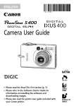
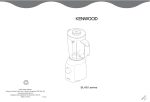
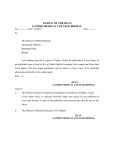
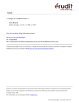
FF 450/FF 450 IR
Fundus Camera
User's Manual
Contents
Page
Notes on safety . . . . . . . . . . . . . . . . . . . . . . . . . . . . . . . . . . . . . . . . . . 3
Labelling ........................................ 3
Instrument safety ................................ 3
Notes on Installation and usage .................... 4
Intended use .................................... 4
Instrument description . . . . . . . . . . . . . . . . . . . . . . . . . . . . . . . . . . . . 5
Construction of basic unit .............................. 5
Controls of fundus camera ............................. 6
IT 350 Instrument Table ............................... 10
Notes on the use of the IT 350 .................... 11
Standard photographic equipment ................. 11
BL 450 Flash Unit .................................... 12
Controlconsole ...................................... 13
Display unit .................................... 14
Key groups ..................................... 14
Installation . . . . . . . . . . . . . . . . . . . . . . . . . . . . . . . . . . . . . . . . . . . . . 16
Removing transport locks .............................. 16
Setting up the fundus camera .......................... 17
Mounting the fixation light ....................... 18
Making electric connections ........................... 19
Mounting the 35 mm camera .......................... 21
O p t i o n s . . . . . . . . . . . . . . . . . . . . . . . . . . . . . . . . . . . . . . . . . . . . . . . . . 22
Photographic equipment for top camera port ............. 22
Mounting the 35 mm camera to Port 2 ............. 22
FF 450 video adapter ................................. 23
Mounting a video camera to Port 2 ................ 23
Internal fixation device ................................ 24
Astigmatism compensator ............................. 24
Demonstration eye with holder......................... 25
1.75x Converter lens .................................. 25
Supplementary lamp.................................. 25
Contents
Page
Operation . . . . . . . . . . . . . . . . . . . . . . . . . . . . . . . . . . . . . . . . . . . . . . 26
Checking the voltage setting ........................... 26
General notes on handling ............................ 27
Preparing the eyepiece ........................... 27
Preparing the BL 450 Flash Unit.................... 27
Preparing the fundus camera ...................... 28
Adjustment to the patient ........................ 28
Operating modes .................................... 30
Fluorescein angiography (FLUO) ................... 30
Red-free photographs ........................... 30
Colour photographs (COLOR) ..................... 31
Fluorescein angiography............................... 31
Contraindications ............................... 31
Injection ....................................... 31
Procedure for a series of fluorescein angiograms ..... 32
Incidents after fluorescein injections ................ 33
Documentation ...................................... 34
Fiow diagram of photographic documentation ....... 34
Program flow in FLUO mode with 35 mm camera .... 35
Program flow for red-free photographs ............. 36
Program flow in COLOR mode .................... 37
Program flow in ICG mode ....................... 38
Care and maintenance . . . . . . . . . . . . . . . . . . . . . . . . . . . . . . . . . . . 39
Replacing lamps ..................................... 39
Replacing the halogen lamp ...................... 39
Replacing the flashbulb .......................... 40
Replacing the filament lamp of the fixation light...... 40
Replacing fuses ...................................... 41
Trouble shooting table ................................ 42
Notes on instrument care .............................. 44
Specifications . . . . . . . . . . . . . . . . . . . . . . . . . . . . . . . . . . . . . . . . . . . 45
Declaration of EC Conformity . . . . . . . . . . . . . . . . . . . . . . . . . . . . . 46
Important for safety:
Notes on safety ....................................... 3
Care and maintenance ............................... 39
Trouble shooting table ................................ 42
Notes on safety
Warning: Risk of injuries!
Strictly observe warning labels!
Q Do not look into the light source, for instance into the objective!
Q When replacing the Halogen lamp, ensure the power cable is disconnected, Only replace halogen lamps only with original types with
holder. Lamps are to be replaced by trained staff only.
Q The flashbulb may only be replaced by service staff.
Instrument safety
Q Proper Operation of the Instrument is imperative for its safe function.
Therefore, read this manuai thoroughly before using the instrument.
If you need supplementary information, please contact our service or
authorised agents.
Q Make sure the set operating voltage corresponds with local mains.
Q Do not cover Ventilation slots.
Q Never leave the instrument switched on and unattended.
Q Disconnect the power cord by grasping its plug. Never pull at the cord.
Q Operate the power switch to turn off the instrument.
Q Make sure the instrument is turned off when it is not in use.
Q The power cord must be connected to a socket with an earthing contact.
Avoid the use of an extension cable. Do not Interrupt the earthing contact
either inside or outside the instrument, äs this may endanger operator,
patient and instrument. If the protection is reduced or any cables are
damaged, discontinue using the instrument. Take care that it cannot be
used by others, and contact service department,
Q The instrument may only be opened by service staff employed with or
authorised by Zeiss.
(Exception: Replacement of halogen lamp)
Q Clean optical components only externally following the instructions given
in this manuai.
Notes on safety
Notes on Installation and usage
Q Do not use the Instrument in hazardous environments. Do not operate it in the presence of flammable anaesthetics and volatile solvents
such äs alcohol, benzine or similar agents.
Q Do not set up the Instrument in humid rooms. Avoid dripping or
splashing water near the Instrument.
Q Only use accessories described in this manual. If you intend to use
other accessories, consult Zeiss Service or sales department prior to
use.
Caution:
This Instrument is a high-quality technical product. To ensure perfect
and reliable Operation, have it checked at least every 12 months by
authorised Service technicians.
intended use
The FF 450 Fundus Camera is a monocular retina camera designed for
routine use. It is suitable for ciinical diagnosis. The fundus camera also
provides documentation of findings by using the appropriate options
(photographic equipment, electronic image sensors with digital basic
Station).
Q The Instrument may not be modified and repaired except by Zeiss
service staff or other authorised persons. The user is responsible for
any consequences resulting from using the Instrument for
applications other than those described in this manual.
Q Read and observe the highlighted safety instructions and notes with
particular attention and care.
Q The instrument may only be operated by trained or instructed staff,
Q The FF 450 Fundus Camera was designed in compliance with the
Standard DIN VDE 0750 Part 1 and IEC 601-1. Manufacture, testing,
Installation, maintenance and repair are subject to relevant German
and international regulations.
Q According to the German Ordinance on Medical Instruments the FF
450 Fundus Camera is a Group 3 instrument.
Q When using the instrument, observe the respective national regulations on the prevention of accidents.
Instrument description
Construction of basic unit
Fig. 1
Construction of basic unit
The main subassemblies of the FF 450 with photographic equipment
include:
1 Fundus camera including illurninating and viewing System with
filters äs well äs ports for documentation Systems.
2 Photographic equipment including NIKON F3-HP camera and
data back.
3 IT 350 Instrument Table with motorised table height adjustment.
4 Instrument base with 3D Joystick for positioning the fundus
camera, brightness control for halogen lamp, and head rest
5 BL 450 Flash Unit comprising connectors for powering fundus
camera, fixation light, supplementary lamp, control console, and
Instrument table.
6 Control console comprising display and keyboard.
7 Head rest comprising vertically adjustable chin rest, forehead rest
strap, and mounting holes for fixation light.
8 Fixation light, swan's neck design, freely movable.
Instrument description
Controls of f undus camera
Fig. 2
Controls of fundus camera
Instrument description
In the view from the right (Fig. 2), the following controls of the FF 450
are illustrated:
1
2
3
4
5
6
7
8
9
10
11
12
Connector for data back of a camera mounted to Port 2.
Connector for camera control of a camera mounted to Port 2.
Eyepiece
Release button
Joystick for horizontal (X-Y) and vertical (Z, by rotation) adjustment
of the Instrument base.
For coarse horizontal adjustment, hold on to the Joystick and push
the Instrument base into the desired direction.
Control for adjusting halogen lamp brightness.
Knurled knob for locking the instrument base.
Hand wheel for tilting the fundus camera.
Knurled knob for internal focusing covering a diopter ränge
of ± 30 dpt.
Slide for pupil reduction. The pupil of the optical System can be
reducedwhen focusing the fundus. The th us extendeddepthoffield
at the same time provides improved reflex-free adjustment.
Protective cap for protecting the objective from dirt and damage
when the instrument is not in use. The protective cap is firmly
connected to the fundus camera through a bead chain. It should be
replaced after use.
Clamp screw to lock the fixation light in its mount.
Instrument description
10
Fig. 3
Controls of fundus camera
Instrument description
In the viewfrom the left (Fig. 3), the following controls of the FF 450 are
illustrated:
1 Forehead rest strap
2 Chin rest, vertically adjustable for reiiable fixation of the patient's
head.
3 internal focusing control
4 Filter wheel with three positions:
C
for colour photographs
RF for red-free photographs
A
for fiuorescein and ICG angiograms (ICG only with FF 450 IR)
5 Clamp screw for swiveliing the fundus camera about its vertical
axis.
6 Knurled sleeve for vertical adjustment of chin rest
7 Cover of lamp unit
8 Field angle selector with three settings: 50° 30° and 20°corresponding to viewing magnifications of 11x, 19x, and 29x,
9 Cover for camera port 2.
10 Lock screw to clamp 35 mm camera to the dovetail mount of the
fundus camera.
11 Cover for astigmatism compensator mount
12 Cover for internal fixation device mount
10
Instrument description
IT 350 Instrument Table
The IT 350 is a motorised Instrument table specially designed for ophthalmic Instruments.
An electric motor drive ailows Optimum adjustment to the height necessary for patient comfort.
Fig. 4
IT 350 Instrument Table
Fig. 4 illustrates the following main components of the IT 350:
1 Tabletop supporting Instrument base and control console.
2 Rocker switch for vertical adjustment of table.
3 Lifting column, containing electric motor drive for vertical
adjustment of table.
4 Power connection with female connector and fuse compartment.
5 Table base with 4 adjusting screws for tabletop levelling.
Instrument description
11
Notes on the use of the IT 350 Instrument Table
For detailed notes on the Operation of the IT 350, see the separate
manual of the IT 350. The features below should be observed for safe
Operation.
Caution: Thermai overload!
The motor of the lifting column is not designed for continuous duty.
Only move the table up or down when it is necessary.
A continuous duty time of > 2.5 min may result in overheating of the
motor. In thiscase, a thermal circuitbreakerwill automatically switch off
the motor. Only after an appropriate cooling time, the motor and thus
the lifting column will operate again.
Standard photographic equipment
The photographic equipment of the FF 450 comprises the NIKON F3-HP
35 mm camera (incl. winder, 2) and data back (1).
The camera is mounted to the bottom camera port (Port 1) äs shown
in Fig. 18. The operations required for mounting the photographic
equipment are described in section Mounting the 35 mm camera.
The data backserves for exposing data (Patient ID, frame no., and date,
onto the film).
Optionally it is possible to mount a second camera of the same type to
the top camera port (Port 2), for instance for taking colour photographs.
For details of the use of the NIKON F3-HP camera, such äs inserting film,
see the provided separate operating instructions of the camera.
1 Data back
2 Winder
Fig. 5
35 mm camera
Instrument description
12
BL 450 Flash Unit
The BL450 Flash Unit contains all electric suppliesfor the FF 450 Fundus
Camera, IT350 InstrumentTable, control console, fixation lamp and the
optional supplementary lamp.
The connectors are located on the rear panel of the unit.
Power switch (1) is the main switch of the f undus camera. Operation of
this switch connects all supply units or disconnects them f rom the mains
supply.
The power switch is the only control on the flash unit required for
Operation of the fundus camera.
1 Power switch
Fig. 6
BL 450, front view
Instrument description
13
Controi console
Photographicrecordingcyclesarecontrolledandmenu-guidedthrough
the keyboard of the control console.
The keyboard is subdivided into 5 groups of keys. They serve for program menu execution according to the selected operating mode,
The current program item and the corresponding parameters are displayed on the alphanumeric display.
Fig. 7
1
2
3
4
5
6
Display
Numerical keys
Reset key
Keys for continuous Variation of parameters, ENTER key
Group of keys for auxiliary functions before image recording
Keys for recording mode selection
Fig. 8
Operating panel of control console
The keys light differently depending on recording mode and operating
state:
Q Key does not light:
The function assigned to this key is not available.
O Key lights green/yellow:
The function/key can be activated for the selected program.
O Key lights red:
In the selected program, this function is active.
Control console
Instrument description
14
Display unit
The display unit consists of a two-line, luminous vacuum fluorescence
display. Italiowsconvenientand reliable reading in almostall conditions.
Thefollowing information is displayed:
Q
Q
G
Q
Q
Q
Q
Next program step to be executed
Operating mode
Photographic port (PORT 1, PORT 2)
Flash energy
Patient ID no.
Frame no.
Current time after timer release
Key groups
[4}
i
1
i i
8
5
5
6
Fig. 9
These keys serve for entering numerical data (e.g. Patient ID) in the
respective menus.
r.:-:.v.;.a
(v-vX-
•i
Numerical keys
l
3
Numerical keys
Reset key
Fig. 10 Reset key
The Reset key provides the following functions:
Q Cancelling a previous numerical entry.
Q Aborting the menu at any point of program execution and returning
in steps to the initial state.
Q By pressing the Reset key once in the Ready state (—>Program
flows), the program will return to the menu "Entry of Patient ID"
(—> Section Program flow).
By pressing the key twice, the program returns to the initial state.
Key group with -, + and ENTER key
Use the - and + keys to change the parameters at predefined intervals
and continuously increment or decrement the Patient ID.
Fig. 11 Key group with ~, + and
ENTER key
Use the ENTER key toconfirm the entered parameters, call the next menu
item or, in the Ready state, release single photographs.
Instrument description
15
Key group for auxiliary f unctions
in the FLUO mode, these keys are accessible to activate specific auxiliary
functions for setting operations or viewing betöre recording is started.
You can press the EXOTE and/or BARR keys to swing the exciter filter or
the barrier filter into the opticai path thus obtaining photo-realistic
imaging in visual observation.
Independent of the current state of these keys, the corresponding filters
will always be swung into the light path when recording Images in the
FLUO mode (fluorescein angiography) except for red-free records.
Fig. 12 Key group for auxiliary
functions
The TIMER key Starts the timer before the actual recording process. If it
is not pressed, the timer Starts with the first exposure.
With the VIEW key you can switch between viewing port (eyepiece) and
documentation port 2.
This function is useful, when between single records you want to check
the setting of the fundus camera or follow the course of an angiography
by video camera.
Recording mode selector keys
35mm
Use these keys to select the recording mode and activate the softwarecontrolled program steps.
The recording modes are characterised by three groups of functions that
activate corresponding control functions of the fundus camera or
standby:
Q Use cotOR, FLUO keys to select the desired operating mode.
Note:
The ICG mode is applicable only for FF 450 versions with an Image
archiving System.
Q Use the ss MM, STILL or VIDEO keys to select the recording medium.
55 MM: 35 mm film acc. to DIN 4335 or ISO 1007-1977
srm: Still Image on CCD camera, fitted at Port 2
VIDEO: Image switched by mirror to PORT 2, Illumination by halogen
lamp, online observation on video camera.
Q Use PORT i (bottom) or PORTS (top) keys to select the port the 35 mm
camera(s) or equivalent Image sensor(s) are connected to.
You can switch between Port 1 and Port 2 at every program step
and operating mode.
Fig. 13 Recording mode selector
keys
16
Installation
Caution:
Betöre Installation carefully read and observe the instructions given in
the chapter "Instrument safety".
The FF 450 Fundus Camera comes in three shipping Containers, They
contain thefollowing subassemblies:
Q FF 450 Fundus Camera, instrument base and head rest with fixation
light in foamed plastic case
Q BL 450 Flash Unit in foamed plastic case
Q Accessories(e.g. photographicequipment)
Betöre Installation, make sure all components are present. The instrument is to be installed by the user.
Removing transport locks
For transport, the movable parts of the fundus camera are secured by
transport locks which should be retained for reuse whenever you want
to change the instrument site.
Remove the following items:
Q 2 foamed plastic pads in the guide rails of the instrument base,
Q 1 small wooden board arranged underneath the locks for horizontal
motion,
Q 1 foamed plastic pad under the Joystick.
Installation
Setting up the fundus camera
• Mount the Instrument base onto the Instrument table and fasten it
to the tabletop,
• Turn clamp screw (7, Fig.2) to lock Instrument base.
• Loosen clamp screw (2) on housing (1) of guide sleeve.
• Carefully lower the FF 450 onto the Instrument base. Take care that
the guide sleeve of the carrier arm smoothly slides onto the mounting
pivot (3) and clamp screw (2) fits into the recess of the mounting
pivot. This screw limits the swivel ränge.
Caution:
Hold the fundus camera vertically when mounting to avoid its canting
on the pivot.
1 Housing of guide sleeve
2 Clamp screw
3 Mounting pivot
Fig. 14 Mounting the fundus camera to the Instrument base
17
18
Installation
Mounting the fixation iight
• Take fixation Iight (1) out of packing.
• Remove knurled screw (2).
Thisscrewisrequiredformounting the fixation Iight toolderversions
of the head rest.
• Plug fixation lamp onto holder (4) on the head rest bracket.
• Turn knurled screw (5) to lock the fixation Iight.
2 3
Fixation Iight
Knurled screw
Electric connector
Holder
Knurled screw
Head rest
Fig. 15 Mounting the fixation Iight
Installation
Making electric connections
The power switch of the flash unit serves äs main switch of the Instrument System. All subassemblies of the fundus camera are powered
through the flash unit,
Caution:
Before making the electric connections between flash unit, fundus camera and control console, make sure to disconnect the power cord of the
flash unitfrom mains.
» On patient side, lay the cables of fundus camera (flash cable, control
cable), äs well äs those of Instrument base (halogen lamp supply) and
head rest (fixation light) between the guide rods of the head rest.
For the cable of the control console, select the shortest possible way
to the flash unit (depending on which side of fundus camera it is set
up).
• Connect the cables to the corresponding connectors to establish the
connections between Instrument and flash unit. The connectors on
the flash unit are labelled accordingly (Fig. 1 6).
Note:
Each connector is different to avoid wrong connections.
Make the following connections to the BL 450 (Fig. 1 6):
1 Cable of fixation light
4 Cable of instrument base
5 Cable of control console
7 FF 450 control cable
8 FF 450 flash cable
Note:
Make sure the safety clip is closed properly.
For power supply of the instrument table, a special power cable must
be connected between IT 350 and flash unit (15, Fig. 16, Fig. 17).
Fig. 1 6 illustrates other connectors for accessories.
• Do notto the mains supply until all instrument connections have been
made. Connect the power cable (9, Fig. 16) to an earthed mains
socket.
19
20
Installation
0
1
2
ffil
3
0
4
•35
Fig. 17 Mains connector on IT 350
0
15
•*F3
«127V T 1.6A
F4
T 1Ä
F5
7 10A
axa i o,a* T o.s» T a*
11
F1iF2
«127V T 1M H
»220V T SA K
12
13
0
1
2
3
4
5
6
7
8
9
10
11
12
13
14
15
0
RCA connector (cinch) for fixation light
Flange socket, 3-pin, for supplementär/ lamp
Flange socket, 5-pin, for foot switch
Flange socket, 5-pin, for Instrument base
Serial port
Connector for control console
Connector for FF 450 control cable
Connector for FF 450 flash cable
Instrument connector with line filter for mains connection
Display window for set line voltage
Fuse holders
Thermal circuit breakers
Warning label "Disconnect power cable before opening"
Nameplate
Instrument connector for connection of IT 350 Instrument Table
Fig. 16 Connectors of flash unit
Installation
21
Mounting the 35 mm camera
The NIKON F3-HP camera is supplied unmounted. The dovetail mount
for connection to the FF 450 and the data back for exposing defined
data are already mounted to the camera.
When handling the 35 mm camera, observe the operating instructions
provided with the NIKON F3-HP.
1
2
3
4
Clampscrew
Dovetail mount
Nikon F3-HP camera
Connectors for 35 mm camera
Fig. 18 Mounting the 35 mm camera to the bottom port (Port 1)
• Adjust the 35 mm camera (3) to 1/15 sec and attach it to dovetail
mount (2) of fundus camera and fasten it by clamp screw (1).
Note:
When attaching the camera, turn the camera by about 45°.
Otherwise, the süghtiy projecting winder would hinder connection to the dovetail mount. When the camera mount has engaged
in the dovetail mount, turn the camera back to normal use
Position.
Make the electric connections between 35 mm camera, data back
and fundus camera. Fig. 19 illustrates the corresponding connectors
on the fundus camera.
1 Connector for camera control
2 Connector for data back
Fig. 19 Connectors for 35 mm
camera
22
Options
Photographic equipment for top camera port
On the top, the fundus camera has a second port for Image recording
(Port 2). Via a FF 450 adapter on this port, various recording Systems can
be connected.
For the FF 450 Fundus Camera with photographic equipment, a NIKON
F3-HP 35 mm camera (without data back) is offered äs an Option.
Mounting the 35 mm camera to Port 2
NIKON F3-HP
4
5
6
7
8
Dovetail mount
FF 450 camera adapter
Cover plate for Port 2
Connector for camera control
Connector for data back
Clamp screw
Mounting threads
Fig. 20 Mounting a 35 mm camera to Port 2
• Loosen the screws of cover plate (4) and remove the plate.
• In place of the cover plate, mount the FF 450 camera adapter (3).
• Attach the NIKON F3-HP camera to dovetail mount (2) and fasten the
camera by means of clamp screw (7).
• Establish electric connection between fundus camera and 35 mm
camera by connecting the cable for camera control to connector (5)
and the data back cable to connector (6).
Note:
When handling the NIKON F3-HP, observe the operating
instructions provided with this camera.
Options
FF 450 video adapter
Port 2 also ailows connection of the FF 450 video adapter. This adapter
accommodates two additional cameras.
Preferably, the Ports A and B of the adapter are provided for video
cameras. However, after connection of an appropriate relay lens, you
may also mount a second 35 mm camera to the video adapter.
Control (3) serves for selecting Port A or B.
Mounting a video camera to Port 2
1 Video camera
2 Dovetail mount A
3
4
5
6
7
8
Port A/B selector control
Cover plate for Port 2
FF 450 video adapter
Clamp screw for dovetail mount A
Clamp screw for dovetai! mount B
Dovetail mount B
Fig. 21 Mounting a video camera to Port 2
• Loosen the screws of cover plate (4) and remove the plate.
• In place of the cover plate, mount the FF 450 video adapter (3).
• Attach the video camera to dovetail mount (2, Port A or 8, Port B) and
fasten the camera by means of clamp screw (6 or 7).
• Establish electric connections between video camera and the
corresponding camera supply and image analysis unit.
U^
Note:
When handling the video camera, observe the operating
instructions provided with the camera.
23
Options
24
Internal fixation device
Fig. 22 Internal fixation device
The internal fixation device is arranged in the plane of the first intermediate image of the retina. This plane lies immediately behind the
ophthalmoscopy lens. The manipulator allows free movement of the
fixation mark in this plane. By moving the mark axially along the optical
axis an ametropia of ± 10 D of the patient can be compensated. Every
point of the field of view is accessible by moving the control handle.
• To mount the internal fixation device, remove cover plate (12, Fig. 3)
from the fundus camera by loosening the two fastening screws.
Replace it with the piate containing the fixation device.
Astigmatism compensator
The astigmatism compensator provides continuous compensation of a
patient's astigmatism. This applicable particularly to astigmatism of
oblique bundles when examining peripheral fundus areas. The compensating ränge is from 0 D cyl to about 20 D cyl at optional angle.
Fig. 23
Astigmatism compensator
• To mount the astigmatism compensator, remove cover plate (8,
Fig. 3) after loosening the two fastening screws.
• Put the astigmatism compensator into the opening and screw it
down.
• Use detent lever (1, Fig. 23) to swing the astigmatism compensating
optics into the optical path. By pushing the lever in and swing it
upward until itclicks in.
• Swivel adjusting screw (3) to set the axis of astigmatism.
The axis iscontinuouslyadjustable in the ränge O c . . . 180°. Readthe
set axis value from scale (4).
• For setting the cylindrical power, turn knurled knob (2) of adjusting
screw. The scale of the knurled knob is provided with a diopter scale.
Options
25
Demonstration eye with hoiderr
For training purposes, a demonstration eye is available.
In use, mount the holder with the demonstration eye to the rod of the
head rest.
Ametropia is adjustable (± 5 D) by sliding the unit longitudinally.
Fig. 24 Demonstration eye with holder
1.75x Converter lens
The 1,75x Converter lens is available for increasing the lateral magnif ication, The Converter lens is mounted between the camera port of the
fundus camera and the 35 mm camera.
• First, remove 35 mm camera from fundus camera.
• Unscrew the dovetail mount from the T2-adapter of the camera.
Store it in an appropriate box.
• Screw the Converter lens into the T2-adapter.
• You can mount the camera to the desired port of the fundus camera
using the dovetail mount of the Converter lens.
Fig. 25 1.75x Converter lens
Supplementary lamp
This lamp serves for illuminating the patient's arm during the injection
for fluorescein angiography. The supplementary lamp mounts to the
head rest.
26
Operation
Caution:
Betöre operating the Instrument, read and observe the instructions
given in the chapter Instrument safety.
Checking the voitage setting
The Instrument is factory-set to the Standard mains voitage of the user's
country, On the BL450 flash unit, you can read the setting in the window
below the power connector on the rear panel.
Makesurethisvaluecorrespondswiththeiocal line voitage. If not, have
the instrument set to the available line voitage by Service staff. In tis case
the fuses must also be changed (—> Chapter Care and maintenance,
Replacing fuses).
)(
f
S
]
^^ (^}
—)
V-
-< ) Für (T35D anl v
•*~s
Nur fOP IT350
F3
F4
F5
<127V T 1,6A T 1A T 1QA
>22QV T 0.8A T 0.5A T 5A
F1;F2
«127V T 12A H
>220V T 6A H
1 Display window indicating the set line voitage
Fig. 26 Location of line voitage display window
Caution:
The user is responsible for maintaining the above mentioned requirementsfor Operation.
Operation
27
General notes on handling
After you have installed and used the fundus camera and its accessories,
you should, if possible, maintain a regulär procedure including the
following operations:
Preparing the eyepiece
• If you are emmetropic, pull out the eyecup of the super high-eyepoint
eyepiece. If you wear glasses push it in.
• Set the diopter setting ring of the eyepiece to 0 D.
• To compensate for your ametropia (up to ± 4 D), turn the diopter
setting ring accordingly. By looking through the eyepiece and turning
the setting ring until the double cross-hair is sharply defined.
Preparing the BL 450 Flash Unit
• Operate power switch to switch on the unit.
• If the fundus camera has not been used for more than two months,
switch on the power supply two hours before starting examinations
to allow the electrolytic capacitors to Charge.
1 Power switch
Fig. 27
BL 450 Flash Unit
28
Operation
Preparing the fundus camera
• Insert film into 35mm camera (—> Operating instructions of NIKON
F3-HP).
• Mount 35mm camera to camera port (—> chapter Installation,
Photographic equipment) and estabiish electric connections.
• Pull fundus camera with Instrument base away from patient.
• Turn control (6, Fig. 29) to set the desired field angle. This will speed
up positioning to the patient's eye.
Adjustment to the patient
Preparing the patient:
• Dilate patient's pupil.
• Sit the patient down. Adjusttheheightof theinstrumenttable. Have
patient rest their chin on chin rest and forehead against forehead
rest. Turn knurled sleeve (—> pp. 8 and 9) until the patient's eye is
level with the marks on the head rest.
• Have patient lean slightly forward so that their forehead and chin are
firmly positioned.
• If necessary, adjust your seat.
Setting the fundus camera:
• Move the Instrument base laterally for alignment to either left or
right eye.
• Remove objective cap now. Not before.
B^=
Fig. 28 Objektivschutzkappe
Note:
The objective cap is connected to the fundus camera with a bead
chain.
• Have patient look to either the external f ixation light (non-examined
eye) or fixation target of the internal fixation device (examined eye).
• Turn the brightness control (4, Fig. 29) on the Instrument base to
adjust observation brightness.
• Move instrument base back and forth to focus the light ring of the
fundus camera onto the patient's pupil.
Operation
If necessary, select appropriate filter of the filter wheel (2)
(—> Section Operating modes).
Turn focusing control (3) to focus onto the fundus oculi,
Eliminate any residual reflections or vignetting by fine adjustment of
the Instrument base. For this, move the Joystick (5) or turn its control
knob for vertical adjustment.
1 Fixation light
2 Filter wheel
3 Focusing control
4 Brightness control of Halogen lamp
5 Joystick with release button
6 Field angle control
Fig. 29 Fine adjustment of fundus camera
29
30
Operation
Operating modes
The fundus camera version with photographic equipment allows the
foliowing operating modes to be employed:
- Fluorescein angiography (FLUQ) with red-free Option
- True color photography (COLOR)
The ICG mode is notavailable in the photographic version äs thetechnical requirements for the use of infrared film are extremely high. Therefore, the !CG mode is provided only for the FF 450 Fundus Camera
version with Image archiving System,
The recording cycles are controlled and menu-guided via the control
console. The basic program flow is illustrated by a flow chart in the
section Documentation. The operations for taking photographic records in the COLOR and FLUO modes are described in the section
Program flow.
Fluorescein angiography (FLUO)
In the FLUO mode, b/w photographs are taken of the patient's eye
dilated forfluorescein angiography.
For this, the patient's eye is illuminated by blue light exciting the injected
solution to emitfluorescence light. The ernitted green light is filtered out
in the documentation path of light.
The keyboard contains control keys to move the exciter filter (blue) and
barrier filter (yellow) in and out before taking the photographs. In this
way, the operator can view the patient's eye the way it will be recorded
subsequently on film or image sensor.
For every image record in FLUO mode, the exciter and barrier filters are
moved in and out automatically.
Fluorescein angiography is a diagnostic method extending over a longer
period. Therefore, documentation of the process is by serial photographs (> Section FLUO, Preparing thepatient).
In the FLUO mode, Software allows for both single and serial
photographs. Images are taken by pushing the button on the Joystick.
Operation
Red-free photographs
Usually red-free photographs are taken before angiography. These
photographs provide high contrast b/w photographs of the vascular
System of the fundus before injection.
For this, turn filter wheel (2, Fig. 29) to position "RF". A sensor detects
the filter and prevents exciter and barrierfilters from being moved into
the optical path when you release a flash.
Coiour photographs (COLOR)
In the COLOR mode, the patient's eye is recorded on a 35 mm colour
film in true colours.
Usually only a few (1 ... 3) photographs are taken in this mode.
Therefore, Software permits only single photographs to be taken
released by pressing the button on the Joystick.
When using the COLOR mode, turn the filter wheel to position "C".
Of course, you can take red-free photographs also in this mode
(—> Red-free photographs).
31
32
Operation
Fluorescein angiography (general notes)
Caution: Observe contraindications!
To avoid any incidents, carefully watch the patient and observe the
existing contraindications for fluorescein injections.
Contraindications include among others:
ü Renal insufficiency
Q Serious cardiovascular diseases
Q Poor general state of health
Q Pregnancy
Injection
The manner of fluorescein injection iscrucial for obtaining high contrast
fluorescence images.
Maximum fluorescein concentration in the vessels of the fundus must
be achieved within the shortest possible time.
• For the injection process, you can mount the optional 12V 5W lamp
to the head rest.
• To obtain a clearly visible fluorescence, carry out the injection within
2 to 3 seconds.
• The injected dose shouid be between 8 and 10 ml of a 10% solution
(for adults) [Prof. Dr. A. Wessing: "Fluoreszenzangiografie der Retina", Textbook and atlas].
• Do not remove the injection needle until the angiogram is finished
(—> Incidents after fluorescein injections).
Procedure for a series of fluorescein angiograms
• First, focus onto the patient's eye without any filters.
• Carefully check the focus setting, äs it is difficult to correct it during
the angiogram series.
It is recommended that the patient is informed of the intended
angiogram series and ask her/him to keep the eye steady and open
wide.
• Set up the menu in the FLUO mode to menu item Ready (> Program
flowin FLUO mode).
• Swiftly inject the fluorescein solution.
• When the contrast medium reaches the eye's vessels (after an "armto-retina" time of about 10 s), Start the angiogram series and continue for about 20 seconds. Then, take single exposures at increasing
intervals.
Operation
Incidents after fiuorescein injections
(Notes were taken from specialist literature.)
Though incidents after injection of fluorescein sodium are rare, they
occur occasionaily. In the literature some serious incidents have been
described.
Q Paravenous injection of smallervolumes of fluorescein sodium is not
uncommon.
Q Vertigo and vomiting occurring shortly after the injection may occur.
Both will subside within a few minutes without any lasting impairment of the patient's general well-being.
Caution:
Considerably more severe are sensitisation effects extending from a
quickly subsiding urticaria to a severe anaphylactic shock. Other incidents includecirculatorysyncopes, respiratorydisorders and generalised
convulsive fits.
Before carrying out fluorescein injections, take appropriate precautions
for possible incidents.
Q Nearby, keep everything at hand required for resuscitation and shock
treatment (oxygen apparatus, cardiovascular drugs, cortisone
drugs).
Q To enable rapid injection of required drugs, do not remove the
injection needle used for fluorescein injection, until the angiogram has been finished.
Q In case of serious incidents, it is recommended to keep the patient
under observation for at least 24 hours. If necessary, consult an
internal specialist.
33
Operation
34
Documentation
Fiow diagram of photographic documentation
Initial state
ff he initial state is automatically sei" after switch on or after pressing reset
i_key_C/CE.______________________________
Select mode
!~0n Instrument versions with photographic equipment, you can choose "j
• between COLOR and FLUO mode,
]
Select camera type
Select port
Set film speed
f The following camera types are avaiTable:
~1
j - 35 mm film
i
- STILL (still image on CCD camera)
:ion)____ _ _ _ _ _ _ _ _ _ _
[You can select between
| - PORT 1 (bottom port) and
~]
j
fßy seiecting the recording medium, film speed is preset to a default
value. To adjust film speed in Steps to the actual speed of the film used,
jaress ^_and_+_key_s^_ _ . _ „ _ _ _ _ _ _ _ _ _ _ _ _ _ _ _ _ _ _ _ __
Entry of patient identification number through numerical keys of control
console. You can vary the displayed patient ID continuously by pressing -
Enter Patient ID no.
For visual observation and adjustment of the object to be recorded, you ~j
can move appropriate filters into the optical path. This selection has no
automatic_filter_selectjpn in_FLUO mode. _ j
Select filter
r
Release film exposure
Next patient or
initial state
By pressing the button on the Joystick and the ENTER key of the control ~|
j console, single flashes are released.
l Serial flashes (FLUO, ICG) are released at 1 s intervals äs long äs you
i
e
e
a
:
e
| s
u¥ -P t!l J^^ ^^^^nj?tJ'l?i9y?^!S ^J^ JP ? §?^i - _ _ _ _ _ _ - _ — l
[ By pressing the reset key you can return to menu item "Enter Patient
~]
. irw, /—— :i —„\ --^|Q[tiaJ^aJe^(£ressjt_twice).___________j
Operation
35
Program flow in FLUO mode with 35 mm camera
The description of operations below is based on the following
prerequisites:
• Fundus camera has been adjusted to the fundus to be recorded,
• Initial state of program has been set by pressing reset key C/CE twice.
The displays appearing at the individual program Steps are shown in the
adjacent column.
• Turn filter wheel to position "A".
• Press FLUO key,
The display requests you to select one of the available camera types
through key group (6, Fig. 8, green lighting keys).
Color
accept ?
35 mm
64
Port 2
Fluo
Select Camera
• Press 35 MM key for b/w photographs..
If you use only one 35 mm camera for recording, it is better to mount
it to the bottom camera port (Port 1). The top camera port (Port 2)
should be reserved for an additional 35 mm camera (—> Section
Program flow in COLOR mode).
• Select PORT 1.
Fluo
35 mm
Select Port
Port
35 mm
400
Porti
Speed
Fluo
Pat-ld:
35 mm
000000
Porti
E: 13
F:000
Fiuo
Film speed is preset by default to 400 ASA.
If the speed of the used f ilm is different, press - or •»• keys to set this value.
• To confirm the film speed setting, press ENTER.
In the next program step, enter the Patient's identification no. for
exposure on the film.
• Use numerical keys to enter Patient ID.
To increment or decrement Patient ID continuously, use - and +• keys.
• To confirm the entered Patient ID, press ENTER,
The instrument is ready now for photographic records.
The display shows the applied flash energy (E: 13) and the current frame
number (F: 000).
Ready
Operation
36
E: 13
F:000
Ready
The preset flash energy has been based on experience.
You can increase or decrease the energy by Steps to adapt it to the
currently existing object-related conditions. For this, use - and + keys.
Note:
In the Ready state, you can reselect the port (Porti <—> Port2).
• To release the flash and activate the camera, press the release button
of the Joystick or the ENTER key.
T: 001
Okay
E: 13
70
F:001
On fiash release, timer is starting and the number of frames taken so far
appears on the display.
If you wish the timer to Start before the first flash, start it manually by
pressing the TIMER key (—> Fluorescein angiography).
m*
Note:
Single photographs are released by short presses of the button of
the Joystick.
You may also release single photographs by pressing the ENTER
key.
To take serial photographs at 1 s intervals, keep the release button
depressed.
• After you have taken the photographs, you can return to the
program item "Entry of Patient ID" by pressing the reset key CICE
once.
• To return to the initial state of the program, press the CICE key twice.
Fluo
accept ?
35mm
400
Porti
• To start another photographic cycle with the same recording
conditions and instrument parameters, press the ENTER key. - The
program will then maintain the previous settings and activate the
Ready state.
Program flow for red-free photographs
Red-free photographs are possible in both FLUO and COLOR modes, the
program flow is analogous to that of these modes (—>pp. 35 ... 38).
• After you have selected FLUO or COLOR mode, turn filter wheel (4,
Fig. 3) to position RF to movethe red-freefilter into the optical path.
• To take the photographs, proceed äs described under Program flow
in FLUO and COLOR mode.
Operation
37
Program flow in COLOR mode
The description of operations below is based on the following
prerequisites:
• Fundus camera has been adjusted to the fundus to be recorded.
• The program has been reset by pressing reset key C/CE twice.
• Turn filter wheel to position "C".
• Press COLQR key.
The dispiay requests you to select one of the available camera types
through key group (6, Fig. 8, green lighting keys),
Color
accept ?
35 mm
64
Port 2
Color
Select Camera
• Press 35 MM key for 35 mm photographs..
If you have mounted a 35 mm camera for b/w photographs to the
bottom port(Port 1), takethe colour photographs with a second 35 mm
camera mounted to the top port (Port 2).
• In this case, select PORTS.
Color
35 mm
Select Port
Port
Color
Speed
35 mm
64
Port 2
Color
Pat-ld:
35 mm
000000
Port 2
E: 4
F:000
Film speed is preset by default to 64 ASA.
If the speed of the used film is different, press - or + keys to set this value.
• To confirm the film speed setting, press ENTER.
In the next program step, enter the Patient's identification no. for
exposure on the film.
• Use numerical keys to enter Patient ID.
To increment or decrement Patient ID continuously, use -and + keys.
• To confirm the entered Patient ID, press ENTER.
The instrument is ready now for photographic records.
The dispiay shows the applied flash energy (E: 4) and the current frame
number (F: 000).
The preset flash energy is based on experience.
You can increase or decrease the energy by Steps to adapt it to the
currently existing object-related conditions. For this, use - and + keys.
l@>
Note:
In the Ready state, you can select the port again (Porti <—>
Port2).
Ready
Operation
38
To release the flash and activate the camera, press the release button
of the Joystick or the Enter ENTER key.
Note:
In the COLOR mode, you can only take single photographs by
single presses of the release button on the Joystick.
After you have taken the photographs, you can return to the
program item "Entry of Patient ID" by pressing the reset key c/ce
once.
Color
accept ?
35 mm
64
Port 2
To return to the initial state of the program, press the CICE key twice.
To start another photographic cycle with the same recording
conditions and Instrument parameters, press the ENTER key. - The
program will then maintain the previous settings and directly activate
the Ready state.
Program flow in ICG mode
Records in ICG mode require the use of a suitable camera System forthe
wavelengths to be evaluated.
The program flow in this mode is analogous to that of FLUO and COLOR
modes. Therefore, description of the individual program Steps will not
be repeated.
Proceed äs described under Program flow in FLUO mode or Program
flow in COLOR mode.
Care and maintenance
Caution:
The Instrument may be modified and repaired only by Service
technicians employed with or authorised by the manufacturer. The
manufacturer is not liable for damages caused by unauthorised
tampering with the Instrument. Such tampering will also forfeit any
rights to claim under warranty.
The maintenance work you may carry out yourself is described below:
Replacing lamps
Warning: Risk of injuries!
Betöre changing the lamp, switch off the Instrument and disconnect its
power cord.
To avoid burns, let the defective lamp cool down, before replacing it.
Caution:
Avoid touching the lamp bulb with bare fingers.
Replacing the Halogen lamp
1 Carrier with holder
for halogen lamp
2 Halogen lamp
3 Fiashbulb
Fig. 30 Location of halogen bulb and flash bulb
• To make the lamps accessible, remove cover (7, Fig. 3). The location
of the lamps is shown in Fig. 30.
• The defective halogen lamp is easily pulled out of its holder.
• Replace defective lamps only with original types. Plug new lamp with
its pins into the holder. Lamp adjustment is not necessary.
• Re-attach the cover, before connecting the instrument to mains
again.
39
40
Care and maintenance
Replacing the flashbuib
Caution:
The flashbuib may be replaced by trained Service technicians only.
The flashbuib has a long life. It is very unlikely that the flashbuib needs
replacing between regulär maintenance checks.
Replacing the filament lamp of the fixation Eight
1 Holder of filament lamp or red blinking LED
2 Filament lamp or LED
3 Cover sleeve
Fig. 31 Replacing the filament lamp or the LED of the fixation light
• Disconnect mains supply.
• Pull off cover sleeve (3) from holder (1) of fixation light.
• Unscrew defective filament lamp or the LED (2) from its holder and
replace it with a new one.
Only use original lamp types.
• Slip cover sleeve onto lamp holder.
• Finally, connect Instrument to mains again.
Care and maintenance
41
RepSacing fuses
Caution:
Before changing fuses, switch off the Instrument and disconnect its
power cord.
The fuses you can replace yourself are arranged on the rear panel of the
BL 450 flash unit and on the base of the lifting column of the IT 350
Instrument Table directly above the mains socket.
• Use a screwdriver to unscrew the fuse link.
• Replace defective fuse, screw in fuse link again.
Use the following fuses:
BL 450 Flash Unit
Symbol/
Protected circuit
Designation acc. to
IEC 127F1
2 fuses; mains input circuit;
lifting System
T 6.3A, 220-240V
T 10A, 100-1 27V
Location
Fuse cartridge in
table base
F3
T 0.8A, 220-240V
T1.6A, 100- 127V
F4
T0.5A, 220-240V
T1A, 100-1 27V
F5
T 5A, 220V-240V
T10A, 100V- 127V
Fig. 32 Fuses on lifting column of
IT350
T = slow-blow.
All other fuses are multifuses mounted to printed circuit boards and thus not replaceable by the user
Table 1
User-replaceable fuses of BL 450 Flash Unit and IT 350 Instrument Table
F1 and F2 are thermal circuit breakers that need not be replaced.
F3
F4
F5
«127V T 1,6A T 1A T 10A
?220V T Q,8A T 0,5A T 5k
35) (05
F1;F2
«127V T 12A H
>220V T 6A H
Fig. 33
Fuses on BL 450
42
Care and maintenance
Troubleshooting table for FF 450 and BL 450
Trouble
Possible cause
Remedy
No electrical function (power
indicator LED of key does not
Power key set to OFF
Press power key, LED must be on.
Power cord not connected
Connect power cord to mains socket
Local mains voltage is different from
factory-set operating voltage
Call service technidan
No electric connection between fundus
camera and flash unit
Connect control cable of fundus camera
with flash unit
Fuse F3 on flash unit blown
Replace fuse F3 on flash unit
light)
No response of fundus camera
(power indicator LED does not
light)
Fuse F1 or F2 on instrument table blown Push in key of F1 or F2 again
Halogen lamp and flashbulb not Connector disconnected
working
Connect control cable of fundus camera
with flash unit
Lamp voltage control set to "Min."
Turn control clockwise
Halogen lamp defective
Replace lamp acc. to chapter "Replacing
lamps"
Fuse of Halogen lamp control circuit
blown
Replace fuse F4 on flash unit
Brightness of Halogen lamp
cannot be adjusted
Connector of instrument base not
connected to flash unit
Establish connection
No continuous adjustment
possible over setting ränge of
brightness control
Lamp control circuit defective
Call service technidan
All functions OK, except for
Halogen lamp
Connector of instrument base not
No response when releasing
photographs on instrument base connected to flash unit
(Joystick)
Establish connection
No release of photographs, error Camera or BAS not properly connected
message appears
Check and make connections.
Care and maintenance
43
Troubleshooting table for FF 450 and BL 450
Trouble
Possible cause
Remedy
No flashes when releasing
photographs
No electric connections between fundus
camera and flash unit
Connect fiash cable to flash unit
Flashbulb defective
Have it replaced by Service technician
Fuse of flash drcuit blown
Replace fuse F5 on flash unit
Bulb of fixation light defective
Replace bulb acc. to chapter "Repladng
lamps"
Connector of head rest cable not
connected to flash unit
Establish connection
Connecting cable not connected to flash
unit
Establish connection
Fixation light does not light
Supplementary lamp does not
light
In the case of malfunctions of mechanical and optical subassemblies, call service technician.
Table 2
Troubleshooting table
44
Care and maintenance
Notes on Instrument care
Because of its simple, enclosed design, the fundus camera is aimost
maintenance-free.
It is, however, necessary to clean optical components occasionally
(ophthalmoscopy lens, eyepieces). To remove dust from accessible
surfaces, use a soft brush.
Clean very dirty painted surfaces with a cloth moistened with weak
detergent.
If necessary, clean the front surface of the lens with an ether/spirit
mixture (1:1) applied to a cotton swab, For cleaning, switch on the
illumination so that you can check the cleaning effect. Clean the surface
by moving the cotton swab or another appropriate tool of the optics
cleaning kit circularly from the lens centre to the edge.
When not in use, cover the Instrument to protect it from dust using the
dust cover provided. Store 35mm camera body and all other accessories
in their storage boxes. Cover camera port and ophthalmoscopy lens
with the plastic caps provided.
Store the original packing material for future transportation or repair.
If you wish it can be returned to the supplier.
Specifications
Field angle
Viewing magnification
Visual observation
Distance
front lens - patient's eye
operator - patient's eye
Compensation of ametropia
Flash rate
Filters
Image size on 35 mm film
Swivel ränge
Instrument table
Ambient conditions
Permissible ambient temperature
Permissible humidity
Electric System
Compliance with Standards
Line voltage
Line frequency
Performance
Fuses
Earthing conductor
Dimensions
FF 450 Fundus Camera
BL 450 Flash Unit
IT 350 Instrument Table
Control console
Table 3 Specifications
45
50°
30°
20°
11x
19x
29x
through spedal 10x eyepiece with reticle,
monocular
42mm
470mm
± 30 D, continuous
1xper second
red-free and filter for fluorescein
angiography,
ICG filter (only with FF 450 IR)
26 mm diameter,
vertically limited to 24 mm
± 45° horizontally
+ 15°/-10° vertically by hand wheel
motorised, asymmetrical design, suitable
for wheelchair patients, 2.5 min shortterm Operation
10... 35 °C (50 ... 95 °F)
0 ... 80% (no condensation)
DINEN 60601-1 (IEC 601-1)
IT350: 115 V/60 Hz, 4,8 A
230 V/50 Hz, 2,4 A
BL 450: 1 00-1 1 0-1 20-1 25-220230-240 V
50 ...60 Hz
600 VA
according to page41
Instrument to be connected only to
sockets with perfect earthing conductor.
430x3 10x800 mm3
480x1 90x470 mm3
880x650xmax.1030mm3
150x1 50x30 mm3
46
Corvformity with EC-RuIes
The FF 450 / FF 450 IR Fundus Camera
complies with the
Q ECDirective89/336/EECoftheCouncilof03.05.1989fortheharmonisation of the regulations of the member states on electromagnetic
compatibiiity
and the
Q German Law on the electromagnetic compatibiiity of Instruments of
09.11.92.
The Instrument satisfies the requirements of the following
Standards:
Radio noise suppression
EN 55011 (07/92)
Noise immunity
EN 60601-1-2
/
Class B
Carl Zeiss Jena GmbH
Zeiss Group
Ophthalmic Instruments Division
D-07740 Jena
Phone: (+493641)642807
Fax:
(+493641)642815
319400-7044.201
FF 450 / FF 450 IR 07.10.1996