1
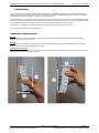
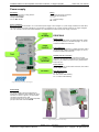
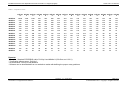
Installation Manual for the Adjustable Active DP Termination T1-Pepper (English) Order code: 101-00212A Installation Manual (English) Adjustable Active DP Terminator T1-Pepper Active RS485 segment termination for non-compliant cable Designed for use with the COMbricks SALT repeater PROCENTEC Klopperman 16 2292 JD WATERINGEN The Netherlands All baudrates Redundant power supply IP 20 with DIN-rail mounting Adjustable pull-up and middle resistor Terminator-T1-Pepper-Manual1-EN.docx Tel.: +31-(0)174-671800 Fax: +31-(0)174-671801 Email: [email protected] Web: www.procentec.com Version 1.1.1 – June 2014 Page 1 / 6 © PROCENTEC 2014 - Copyright - all rights reserved Installation Manual for the Adjustable Active DP Termination T1-Pepper (English) Order code: 101-00212A Introduction The T1-Pepper provides active and reliable adjustable termination for PROFIBUS segments which use non-PROFIBUS cable. By using this component it is possible to use UTP cable, telephone cable or other non-PROFIBUS cable. This can save on installation time and cabling costs when extending or refitting your automation network. This product has a couple of special features which makes it a very useful infrastructure component; it has two adjustable terminating resistors. The ‘Pull up’ rotary switch is used to adjust the idle voltage level (normally 1V), which means you can raise the idle voltage for improved EMC defense. The ‘Middle’ rotary switch is used to change the impedance value for the cable. It also features a redundant power supply and diagnostic LEDs to indicate the status of each power source. The T1-Pepper can be installed on a standard DIN-rail. Installation instructions Location The T1-Pepper can be installed everywhere in a non-hazardous area that complies with IP 20 (DIN 40 050) and the specified o temperature range of -20 to +60 Celsius. Position The T1-Pepper can be installed in every position, but it is recommended to install it with the green PROFIBUS connector pointing down. In this position it is easier to read the status display. Mounting and dismounting The T1-Pepper has to be mounted on a 35 mm DIN-rail with a minimum width of 60 mm. Fig. 2 and Fig. 1 illustrate how to mount and dismount the T1-Pepper on and from the DIN-rail. Fig. 2 Mounting; pull-down and push Terminator-T1-Pepper-Manual1-EN.docx Fig. 1 Dismounting; Push-up and pull Version 1.1.1 – June 2014 Page 2 / 6 © PROCENTEC 2014 - Copyright - all rights reserved Installation Manual for the Adjustable Active DP Termination T1-Pepper (English) Order code: 101-00212A Power supply Parameters The power supply has to comply with the following specifications: Voltage: 19 to 28 VDC Current: Min. 65 mA Wiring The leads of both power connectors have to be wired as follows: “-“ = 0 V “+” = Positive Voltage SH = Earth Power redundancy Both power connectors are linked 1-on-1 to the internal power supply of the T1-Pepper. If 1 power supply would fail, the other takes over without delay time. When redundancy is not required, it is sufficient to use 1 power connector. When the T1-Pepper is flipped o 180 , the connectors can be used without alteration. Fig. 3 illustrates the location of the power supply connectors. PROFIBUS Middle resistor Change the ‘middle resistor’ by rotating this switch. Select the required impedance in the table on page 5, or use our convenient software tool TermCalc. Pull-up Resistors Change the ‘pull-up resistors’ by rotating this switch. Select the required idle voltage in the table on page 6, or use our convenient software tool TermCalc. Auxiliary resistor connection In some very special cases, you can attach a custom termination for cable with specifications not covered by this product. If you choose to do this, the rotary switches must both be set to 0. Screw terminal The T1-Pepper has one Bus Cable connector, this is where the DP segment ends. Bus cable pin layout Pin “A”: Green wire Pin “B”: Red wire Pin “SH”: Direct cable shielding Pin “I”: Indirect cable shielding Fig. 3 Structure of the T1-Pepper Ground Clip It is recommended to use the supplied GC-01 ground clip to attach the cable shield to the screw connector, as shown in figure 4, for easier shield connection and better strain relief. The Ground Clip GC-01 can be ordered separately per 25pcs with order code 101-00201B. Fig. 4 Using the Ground Clip Terminator-T1-Pepper-Manual1-EN.docx Version 1.1.1 – June 2014 Page 3 / 6 © PROCENTEC 2014 - Copyright - all rights reserved Installation Manual for the Adjustable Active DP Termination T1-Pepper (English) Order code: 101-00212A Diagnostic LEDs OFF Blinking ON P1 Power is OFF or an internal failure. Check if P2 is on. Power supply not stable or an internal failure. Check if P2 is on. Power supply OK. P2 Power is OFF or an internal failure. Check if P1 is on. Power supply not stable or an internal failure. Check if P1 is on. Power supply OK. Technical Data Adjustable Active DP Termination T1-Pepper Dimensions and weight Dimensions L x W x H (mm) 106 x 55 x 33 mm (without plugs) 106 x 55 x 55 mm (with plugs) Weight Approximately 125 g Ambient conditions o Operating temperature -20 to +60 Celsius Isolation class IP 20 (DIN 40 050) Protocol specifications Supported Protocols DP-V0, DP- V1, DP-V2, FDL, MPI, FMS, PROFIsafe, PROFIdrive and any other FDL based protocol. Transmission speed 9,6 kbps to 12 Mbps (including 45,45 kbps), depending on the cable quality. PROFIBUS cable specifications Cable lengths Depending on cable quality: 1200 m at 9,6 kbps to 93,75 kbps 1000 m at 187,5 kbps 400 m at 500 kbps 200 m at 1,5 Mbps 100 m at 3 Mbps to 12 Mbps Wire diameter < 2,5 mm Wire type Stranded or Solid core Termination range (MIDDLE) 94 .. 940 Ohm (DC) Idle voltage range (PULL-UP) 0 .. 5 V 2 57 .. 1500 Ohm (AC) Download our software tool to calculate the correct settings for the rotary switches from www.procentec.com/downloads Power supply specifications Nominal supply voltage Current consumption Power dissipation 19 to 28 VDC 65 mA at 24 VDC Max. 2 W Redundancy Power LED Reverse polarity protection Yes (Power 1 OR Power 2) Power 1 OR Power 2 Yes Wire diameter < 2,5 mm Terminator-T1-Pepper-Manual1-EN.docx 2 Version 1.1.1 – June 2014 Page 4 / 6 © PROCENTEC 2014 - Copyright - all rights reserved Installation Manual for the Adjustable Active DP Termination T1-Pepper (English) Order code: 101-00212A Table 1 - Impedance value Middle 0 Middle 1 Middle 2 Middle 3 Middle 4 Middle 5 Middle 6 Middle 7 Middle 8 Middle 9 Middle A Middle B Middle C Middle D Middle E Middle F Pull‐Up Pull‐Up Pull‐Up Pull‐Up Pull‐Up Pull‐Up Pull‐Up Pull‐Up Pull‐Up Pull‐Up Pull‐Up Pull‐Up Pull‐Up Pull‐Up Pull‐Up Pull‐Up 0 1 2 3 4 5 6 7 8 9 A B C D E F OPEN 1500 1200 667 560 408 382 304 270 229 220 192 182 162 158 143 940 578 527 390 351 284 272 230 210 184 179 160 153 139 135 124 780 513 473 359 326 268 256 219 201 177 172 154 148 134 131 121 426 332 315 260 242 208 201 178 165 149 145 132 128 118 115 107 360 290 277 234 219 191 185 165 154 140 137 125 121 112 110 102 260 222 214 187 178 159 155 140 133 122 119 111 107 100 98 92 246 212 204 180 171 154 150 136 129 119 116 108 105 98 96 91 195 173 168 151 145 132 129 119 113 105 104 97 94 89 87 83 182 162 158 143 137 126 123 114 109 101 100 93 91 86 85 80 152 138 135 124 120 111 109 102 97 92 90 85 83 79 78 74 148 134 131 121 117 108 106 99 95 90 88 83 82 77 76 73 128 118 115 107 104 97 96 90 87 82 81 77 75 71 71 67 121 112 110 102 99 93 92 87 84 79 78 74 73 69 69 66 107 100 98 92 90 85 84 79 77 73 72 69 67 65 64 61 105 98 96 90 88 83 82 78 75 72 71 68 66 64 63 60 94 89 87 83 81 77 76 72 70 67 66 63 62 60 59 57 Remarks: - Example - Standard PROFIBUS cable: Pull-Up 6 and Middle 6 (150 Ohm and 1.22 V) - Termination without power: Pull-Up 0 - No termination: Pull-Up 0 and Middle 0 - Software can be downloaded from our website to assist with defining the proper rotary positions Version 1.1.1 – June 2014 Terminator-T1-Pepper-Manual1-EN.docx Page 5 / 6 © PROCENTEC 2014 - Copyright - all rights reserved Installation Manual for the Adjustable Active DP Termination T1-Pepper (English) Order code: 101-00212A Table 2 - Idle voltage Middle 0 Middle 1 Middle 2 Middle 3 Middle 4 Middle 5 Middle 6 Middle 7 Middle 8 Middle 9 Middle A Middle B Middle C Middle D Middle E Middle F Pull‐Up Pull‐Up Pull‐Up Pull‐Up Pull‐Up Pull‐Up Pull‐Up Pull‐Up Pull‐Up Pull‐Up Pull‐Up Pull‐Up Pull‐Up Pull‐Up Pull‐Up Pull‐Up 0 1 2 3 4 5 6 7 8 9 A B C D E F OPEN 5.00 5.00 5.00 5.00 5.00 5.00 5.00 5.00 5.00 5.00 5.00 5.00 5.00 5.00 5.00 0.00 1.19 1.41 2.07 2.28 2.68 2.76 3.03 3.18 3.36 3.40 3.55 3.60 3.72 3.74 3.83 0.00 1.03 1.23 1.85 2.05 2.44 2.53 2.81 2.95 3.15 3.19 3.35 3.41 3.53 3.56 3.66 0.00 0.62 0.75 1.21 1.38 1.72 1.79 2.06 2.21 2.41 2.46 2.63 2.70 2.84 2.87 2.99 0.00 0.54 0.65 1.06 1.22 1.53 1.60 1.86 2.00 2.20 2.25 2.42 2.49 2.63 2.66 2.79 0.00 0.40 0.49 0.82 0.94 1.21 1.27 1.50 1.63 1.81 1.86 2.02 2.08 2.22 2.26 2.38 0.00 0.38 0.47 0.78 0.90 1.16 1.22 1.44 1.57 1.75 1.79 1.95 2.02 2.16 2.19 2.31 0.00 0.31 0.38 0.64 0.74 0.97 1.02 1.21 1.33 1.49 1.53 1.68 1.74 1.88 1.91 2.03 0.00 0.29 0.35 0.60 0.70 0.91 0.96 1.15 1.26 1.42 1.46 1.61 1.67 1.80 1.83 1.94 0.00 0.24 0.30 0.51 0.60 0.79 0.83 1.00 1.10 1.25 1.29 1.42 1.48 1.60 1.63 1.74 0.00 0.23 0.29 0.50 0.58 0.77 0.81 0.98 1.07 1.22 1.25 1.39 1.44 1.56 1.59 1.70 0.00 0.20 0.25 0.44 0.51 0.68 0.72 0.87 0.96 1.09 1.12 1.25 1.30 1.41 1.44 1.54 0.00 0.19 0.24 0.42 0.49 0.65 0.68 0.83 0.91 1.04 1.08 1.20 1.25 1.36 1.38 1.48 0.00 0.17 0.21 0.37 0.44 0.58 0.62 0.75 0.83 0.95 0.98 1.09 1.14 1.24 1.26 1.36 0.00 0.17 0.21 0.36 0.43 0.57 0.60 0.73 0.81 0.93 0.96 1.07 1.12 1.22 1.24 1.34 0.00 0.15 0.19 0.33 0.39 0.52 0.55 0.67 0.74 0.85 0.88 0.98 1.03 1.12 1.15 1.24 Remarks: - Example - Standard PROFIBUS cable: Pull-Up 6 and Middle 6 (150 Ohm and 1.22 V) - Termination without power: Pull-Up 0 - No termination: Pull-Up 0 and Middle 0 - Software can be downloaded from our website to assist with defining the proper rotary positions Version 1.1.1 – June 2014 Terminator-T1-Pepper-Manual1-EN.docx Page 6 / 6 © PROCENTEC 2014 - Copyright - all rights reserved