1
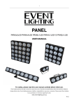
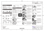
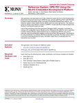
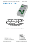
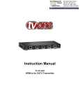
PIXEL TOUCH PCB
USER MANUAL
PRODUCTION DESCRIPTION
CAT WALK PANEL is a wonderful LED display screen integral with 25 three-in-one RGB LEDs, featuring auto
DMX addressing and inductive touch control.
FEATURES
- Automatic DMX addressing
- Innovative control by inductive touching
- Easy & one-for-all setting
- Dazzling LED display suitable for various occasions
- Remarkable interactive lighting-up to walking or dancing
SPECIFICATIONS
OPERATING VOLTAGE
24VDC
CURRENT CONSUMPTION
450mA
MAX CURRENT INPUT
LIGHT SOURCE
6A
Full color 5050 SMD LEDs (25pcs)
PIXEL DISTANCE
40mm
INDUCTIVE DISTANCE
20mm Max
INDUCTIVE TIME
60ms Min
DIMENSIONS
200(L)x200(W)x10(H)mm
WEIGHT
225g
INSTALLATION & OPERATION GUIDE
1 Field Connection
Connect the first unit to the 24VDC power supply (and a DMX controller, if necessary). Then link other units
to it in a line by using the power/data cables. Up to 24 units can be linked together by DMX1000K and 6 units
by DMX512.
NOTE:
i) The nominal wattage of the power supply in use must be above the loading of the whole line of units,
otherwise extra power supplies will have to be used, so as to avoid risk of over-loading.
Ii) The maximum permissible current of the power/data cable is 6A. Always keep input current below 6A.
2 Inductive Control
When the units are duly connected and powered, and an object eg finger, foot, etc comes within the
inductive range of the LEDs of a unit, the LEDs will automatically change from background color (manually
preset or DMX controlled) to touch-color, and turn back to background color when the object goes out of the
inductive range,.
3 Auto DMX Addressing
W h e n C AT WA L K PA N E L u n i t s a r e l i n k e d t o g e t h e r a n d c o n t r o l l e d b y a D M X p r o t o c o l , D M X c h a n n e l s w i l l b e
automatically addressed in numeric order (D1 ~ D25), starting from red, green and then blue section of the
first LED (position designator - D1) of the first unit. This means a single unit shall takes 75 DMX channels of
which each three channels are assigned to one LED (1st channel for red, 2nd for green and 3rd for blue).
24-004-2896-00
Rev1.1
4 How to Get the Unit Ready for Use
Start Setting
Turn on the LEDs one by one with a finger or similar object along the track indicated in Fig 1. Follow the track
a second time and then make the finger stay at LED D13 (the central one) till all the LEDs start twinkling,
which means the unit now has moved into setting mode and has been ready for further setting.
D1
Power & data input
D13
CDV42
DNG
XMD
DNG
-D
+D
D25
Fig 1
NOTE
i) Only the first unit in the line linked by DMX cables must be preset. Other units will follow the same way of
the first unit.
Ii) During the setting, m ake sure that intervals of touching between every two LEDs are less than 2 seconds.
The following table gives relevant information concerning the LEDs which may be used as functional
buttons during setting.
LED Line
Line 1 (D1~D5)
LED Color
light blue (default setting)
Line 2 (D6~D10)
red ( 0% intensity)
Line 3 (D11~D15)
green
Line 4 (D16~D17)
blue
Line 5 (D21~D25)
red (default setting)
Signification
touch-color (variable as per the mixing of the red,
green, and blue sections)
same as the red section of touch-color
(syncrhonizing with Line 5 when it is red in color )
same as the green section of touch-color
(syncrhonizing with Line 5 when it is green in color)
same as the blue section of touch-color
(syncrhonizing with Line 5 when it is blue in color)
the color section(red, green or blue) under setting
Touch Color
After the unit enters setting mode, the following table tells the color status of the LEDs and how to use the
signs to finish touch-color setting.
LED Line
Line 1 (D1~D5)
LED Color
light blue (default setting)
Line 2 (D6~D10)
Line 3 (D11~D15)
Line 4 (D16~D17)
Line 5 (D21~D25)
red ( 0% intensity)
green
blue
red (default setting)
Signification
touch-color (variable as per the mixing of the
red, green, and blue sections)
red section of touch-color
green section of touch-color
blue section of touch-color
the color section(red, green or blue) under setting
Touch D21, Line 5 will change from red to green. Touch D21 again, the line will change to green. In this way
users may individually set the red, green and blue sections of touch-color.
Touch-delay Time
Touch D21 again to finish touch-color setting and start to set touch-delay time. Now Line 5 is white in color. A
single touch on D22/D23 will increase/decrease touch-delay time by 0.1 second and holding it for 2
seconds will greatly speed the adjusting. Please view the following information revealing how the LEDs
demonstrate the time values.
LED (Time Indicator)
LED Color
Indicated Delay Time per LED (sec)
Any of Line 1 (D1~D5)
red/white
0.1 / 0.2
1/2
Any of Line 2 (D6~D10)
red/white
Any of Line 3 (D11~D15)
red/white
10 / 20
Any of Line 4 (D16~D20)
red/white
100 / 200
~3~
The maximum touch-delay time available is 530 sec. Please view the formula below to bring out the exact
touch-delay time:
LED amount of the same line & color x its unit time value) + time values of other LEDs = Touch-delay Time
Background Color
Touch D21 to enter background color setting. Please view the following table about the LED significations.
LED Line
Line 1 (D1~D5)
LED Color
green (default setting)
Line 2 (D6~D10)
red ( 0% intensity)
Line 3 (D11~D15)
green
Line 4 (D16~D17)
blue
Line 5 (D21~D25)
red (twinkling)
Signification
background color (variable as per the mixing of the
red, green, and blue sections)
red section of background color (syncrhonizing with
Line 5 when it is red in color )
green section of background color(syncrhonizing
with Line 5 when it is green in color)
blue section of background color (syncrhonizing
with Line 5 when it is blue in color)
the color section(red, green or blue) under setting
Touch D21 once and then twice, Line 5 will change from red to green and blue. Now the unit has been at the
end of the whole setting circle. Touch D21 again, the setting will move back to the first item of touch-color
setting.
System Connection
It is required to make a proper system connection prior using this fixture, the following contents present you
the single module connection methods on next page.
~3~
DMX input
6pin Extension Cable 0.09m
First Cable 1.5m
~4~
Catwlak Panel Single Module Connection Schematic Diagram
24VDC, 6.5A
Transformer
6pin Extension Cable 0.9m