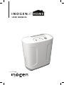
1
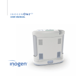
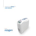
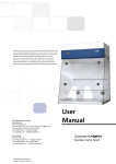
user manual
®
1
Contents
Chapter 1
1
Glossary of Symbols
Chapter 2
Chapter 3
2
2 2 3 Warnings, Cautions and Contraindications
Contraindications
Warnings
Cautions
4
4 Indications for Use
Indications for Use
Chapter 4
4
4 5 5 User Interfaces, Controls and Serviceable Items
User Interfaces
User Controls
Serviceable Items
Chapter 5
6
Operating Instructions
Chapter 6
7
Audible and Visual Indicators
Chapter 7
10
Troubleshooting
Chapter 8
10
10 11 11 11 12 13 Cleaning, Care and Maintenance
Cleaning and Care
Routine Maintenance
Replacement Parts and Recommended Accessories
Service
Column Change Procedure
Storage
Chapter 9
13
Specifications
2
1. Glossary of Symbols
Symbol Key
WARNING
A warning indicates that
the personal safety of the
patient may be involved.
Disregarding a warning
could result in significant
injury
CAUTION
A caution indicates that
a precaution or service
procedure must be
followed. Disregarding a
caution could lead to a
minor injury or damage to
equipment
On/Off (Power)
ONLY
Do not dispose of in
unsorted municipal waste
AC Power
ONLY
Keep Dry
IP21
Flow setting indicator
Blue Indicator Light
No Smoking
No Oil or Grease
Do Not Disassemble
ONLY
Enclosure Ingress
Protection against
solid objects of 12.5mm
minimum diameter and
vertically falling drops of
water
Manufacturer
Complies with applicable
EU directives including
medical devices directive
General alarm indicator light
Follow instructions for use
Type BF Applied Part
Class II Equipment
No Open Flames
U.S. Federal Regulation
Restricts this device to sale
by order of physician. May
also be applicable in other
countries
As Packaged (Per Box)
EC REP
Authorized representative
in the European
Community
Fragile
Humidity
Temperature
This Side Up
1
2. Warnings, Cautions and Contraindications
Contraindications
•
This equipment is to be used as an oxygen supplement and is NOT
INTENDED to be life supporting or life sustaining.
Warnings
•
•
•
•
•
•
•
•
•
2
The device produces concentrated oxygen gas which accelerates
combustion. DO NOT USE THE DEVICE WHEN SMOKING OR NEAR OPEN
FLAME, MATCHES, PETROLEUM, OIL, GREASE, SOLVENTS, RADIANT HEATERS,
AEROSOLS etc. Use only water based lotions or salves that are concentrated
oxygen compatible during oxygen therapy.
Concentrated oxygen makes it easier for a fire to start and spread. Do not
leave the nasal cannula on upholstery or other fabric such as bedding or
personal clothing if the oxygen concentrator is turned on but not in use.
Concentrated oxygen will make the materials flammable. Turn off the
oxygen concentrator when not in use.
Do not use the oxygen concentrator in the presence of pollutants, smoke or
fumes, flammable anesthetics, cleaning agents or other chemical vapors.
This may internally contaminate the oxygen concentrator and degrade its
performance.
Do not use the oxygen concentrator if either the plug or the power cord is
damaged to prevent accidental electrical shock.
Do not submerge the oxygen concentrator in liquids, expose to liquids, or
otherwise allow liquids to enter into the case, this may lead to electrical
shock and/or damage. If the oxygen concentrator is exposed to liquids turn
it off and unplug from electrical outlet before attempting to clean and dry
the liquid spill.
When using a compatible humidifier do not refill humidifier while
attached to the oxygen concentrator. Remove the humidifier from the
oxygen concentrator prior to refilling to prevent accidental spills on the
concentrator and prevent electrical shock hazard.
Do not use cleaning agents other than those specified in this manual.
Always unplug the oxygen concentrator before performing any cleaning.
Do not use alcohol, isopropyl alcohol, ethylene chloride, or petroleum based
cleaners. This may impair the proper function and/or increase the risk of
fire and burns.
Do not disassemble the oxygen concentrator or attempt any maintenance
other than tasks described in this user manual; disassembly creates a
hazard of electrical shock and will void the warranty. Servicing of the
concentrator is to be performed by qualified and trained personnel only.
Do not use any columns other than those specified in this user manual.
The use of non-specified columns may create a safety hazard and/or impair
equipment performance and will void the warranty.
•
•
To avoid danger of choking and strangulation hazard, keep tubing away
from children and pets.
If you begin to feel ill or are experiencing discomfort while using the oxygen
concentrator, consult your health care provider immediately.
Cautions
•
•
•
•
•
•
•
•
•
•
•
•
USA Federal law restricts this device to sale or rental by or on the order of
a physician, or any other practitioner licensed by the State in which he/
she practices to use or order the use of this device; may also be applicable
in other countries. Under certain circumstances, the use of non-prescribed
oxygen therapy can be hazardous.
Availability of an alternate source of oxygen is recommended in case of
power outage or mechanical failure. Consult your equipment provider for
type of back-up system recommended.
Additional monitoring or attention may be required for patients using this
device who are unable to hear or see alarms or communicate discomfort. If
the patient shows any signs of discomfort, a physician should be consulted
immediately.
Accessories not specified for use with the oxygen concentrator may
impair performance. Always use accessories according to manufacturer’s
instructions.
Nasal cannula should be rated 5 liters per minute to ensure proper patient
usage and oxygen delivery.
Replace the nasal cannula on a regular basis. Check with your equipment
provider or health care professional to determine how often the cannula
should be replaced.
It is recommended the oxygen concentrator accessory tubing and cannula
include a means to reduce the propagation of fire.
Do not operate the concentrator without the intake filter and particle filter
in place. Particles drawn into the oxygen concentrator may damage the
equipment.
Refer to the environmental range specifications for proper storage and use
conditions. Temperatures in excess of the indicated range may cause device
malfunction.
Do not obstruct air intake or exhaust when operating the oxygen
concentrator. Blockage of air circulation or proximity to a heat source may
lead to internal heat buildup and shutdown or damage. Always maintain a
minimum of six inches of clearance.
Do not place anything in the power supply port other than the supplied
wall cord. Avoid the use of electrical extension cords with the concentrator.
If an extension cord must be used, use an extension cord that has an
Underwriters Laboratory (UL) Mark and a minimum wire thickness of 18
gauge. Do not connect any other device to the same extension cord.
Do not sit or stand on the concentrator, doing so can be hazardous.
3
In order to ensure a safe installation and operation of the Inogen At Home
Oxygen Concentrator Model GS-100, read and understand this entire manual
before using the device.
The Inogen At Home Oxygen Concentrator has a 5 year expected life except 1 year expected life for user serviceable sieve bed columns.
3. Indications for Use
The Inogen At Home Oxygen Concentrator is used on a prescriptive basis by
patients requiring supplemental oxygen. It supplies a high concentration
of oxygen and is used with a nasal cannula to channel oxygen from the
concentrator to the patient. The Inogen At Home Oxygen Concentrator may be
used in a home or institution.
4. User Interfaces, Controls and Serviceable Items
Blue Indicator
Light
Flow Setting Indicator
Flow
Control
On/Off Button
User Interfaces
General Caution Indicator
General Caution Indicator Light (Low, Medium Priority Alarm)
A yellow light indicates either a change in operating status or
a condition that may need response. A flashing light is higher
priority than non-flashing.
Blue Indicator Light (Change Column Soon)
Column maintenance is required within 30 days. Contact your equipment provider to arrange service.
4
User Interfaces
Audible Indicators
An audible alarm (beep) indicates either a change in operating
status or a condition that may need response (alarm). More
frequent beeps indicate higher priority conditions.
Flow Setting Indicator
A green indicator light indicates the selected flow setting.
User Controls
ON / OFF Button
Press once to turn “ON”; Press and hold for one second to turn
“OFF”.
Flow Setting Control Buttons
Use the – or + flow setting control buttons to select the setting
as shown on the display. There are five settings, from 1 to 5. Serviceable Items
Particle Filter
The filter must be in place at the intake end of the
concentrator during operation. Air Inlet Filter
The filter must be in place at the top of the
concentrator during operation.
Cannula Nozzle Fitting
The nasal cannula connects to this nozzle for output of oxygen.
Nozzle
Fitting
Nasal Cannula
Nasal cannulas should be replaced on a regular basis, consult
with your physician or equipment provider, or cannula
manufacturer’s instructions.
5
5. Operating Instructions
1. Place the concentrator in a well-ventilated location; air
intake and exhaust must have clear access. Ensure
that the concentrator is at least 6 inches (15 cm.)
away from walls, furniture and curtains that could
impede adequate airflow to the device.
2. Ensure particle filter is in place.
3. Ensure intake filter is in place.
4. Follow instructions A or B below:
A. If you are not using a humidifier bottle, connect your nasal cannula tubing to the nozzle fitting. Nozzle fitting is located on the top of the concentrator. See illustrations 4A1 and 4A2.
B. If you are using a humidifier bottle, follow the manufacturer’s instructions. Place the humidifier bottle in the designated holder. See illustrations 4B1 and 4B2.
5. Attach the power cord to the back of the concentrator and plug the other end into an electrical outlet. Do not position the concentrator so that it is difficult to disconnect the power cord. Turn on the concentrator by pressing the ON/OFF button . See illustration 5. A single short beep will sound and all indicator lights will illuminate for a few seconds.
6. Use the or buttons to adjust the device to the prescribed setting. There are five flow settings, from 1 liter per minute to 5 liters per minute. The current setting can be viewed on the display. The green LED will
illuminate once the set flow rate of oxygen is achieved. You may begin breathing from the device; the required oxygen concentration is normally reached within five minutes after device is powered on.
7. Ensure that the tubing is not kinked or pinched in any way and that oxygen is flowing through the nasal cannula. If oxygen is not flowing, the green LED will not be illuminated. Refer to the troubleshooting guide section of this manual.
8. Adjust the nasal cannula so that it is properly aligned on your face or as directed by your healthcare provider.
9. Turn off the concentrator by pressing the ON/OFF button . Turn off the concentrator when not in use. Nozzle
Fitting
4A1
4A2
4B1
4B2
6
5
6. Audible and Visual Indicators
Blue
Indicator Light
Flow Setting
Indicator
Yellow
Indicator Light
The concentrator has an audible alarm and three visual indicators (green, yellow and blue).
Notifications
The concentrator monitors various parameters during operation and utilizes an intelligent alarm system to indicate a malfunction of the concentrator.
Mathematical algorithms and time delays are used to reduce the probability of false alarms while still ensuring proper notification of an alarm condition
If multiple alarm conditions are detected, the highest priority alarm will be
displayed.
To insure that audible notifications may be heard, the operators position must
be determined to suit the surrounding noise level.
Note that failure to respond to the cause of an alarm condition for low, medium
and high priority alarms potentially will result in discomfort or reversible minor
injury only and develop within a period of time sufficient to switch to a backup
source of oxygen.
The following notification messages are accompanied by an audible and/or
visual indicator.
Indicator
Flow rate on LED Display
Condition/Action/Explanation
Current flow rate of oxygen being displayed at a
setting from 1-5 liters per minute.
Flow rate indicator
Flow status indicator is green.
Blue Indicator Light
Column maintenance is required within 30 days. Contact your equipment provider to arrange service.
7
Low Priority Alarms
The following low priority alarm messages are accompanied by a double beep
and a solid yellow light.
Indicator
Condition
Action/ Explanation
4
Low Oxygen
Concentrator is producing oxygen at a slightly
decreased level. Contact your equipment
provider to arrange service.
3
Service Needed
The concentrator is operating to specification
but requires service at the earliest convenience.
Contact your equipment provider to arrange
service.
2
Sensor Fail
One of the concentrator’s sensors has
malfunctioned. If the condition persists, contact
your equipment provider to arrange service.
Flow setting flashing
Low Flow
The concentrator is producing oxygen at a
slightly decreased rate. If condition persists,
contact your equipment provider to arrange
service.
Medium Priority Alarms
The following medium priority alarm messages are accompanied by a triple beep,
repeated every 25 seconds, and a flashing yellow light.
Indicator
Condition
Action/ Explanation
5
Oxygen Error The concentrator is producing oxygen at a
low concentration. Switch to a backup oxygen
source and contact your equipment provider to
arrange service.
4
Flow Error
Proper oxygen delivery has not been detected.
Check for kinked tubing. If condition persists,
switch to a backup oxygen source and contact
your equipment provider to arrange service.
8
High Priority Alarms
The following high priority alarm messages are accompanied by a five beep
pattern, repeated every 10 seconds and a flashing yellow light warning
indicating immediate response by the operator is required.
Indicator
Condition
Action/ Explanation
5
Fire Hazard Smoke has been detected inside the device and
device is shutting down. Allow the concentrator
to air out in a smoke-free environment and
restart. If condition persists, switch to a backup
source of oxygen and contact your equipment
provider.
4
System Hot
Concentrator temperature is too high for
operation. Ensure air intake and outlet vents
have clear access and particle filters are clean.
Allow the concentrator to cool for 10 minutes
and restart. If condition persists, switch to a
backup source of oxygen and contact your
equipment provider.
3
System Cold
Concentrator temperature is too cold for
operation. Allow the concentrator to warm
up in a room temperature environment for 10
minutes and restart. If condition persists, switch
to a backup source of oxygen and contact your
equipment provider.
2
System Error
Switch to a backup source of oxygen and
contact your equipment provider.
Sound indicator
only
Power Error
Concentrator lost power during operation.
Try unplugging the power cord and plugging
it back in. If alarm does not reset, press and
hold the power button down for 2 seconds. If
condition persists, switch to a backup source of
oxygen and contact your equipment provider.
p,
NOTE When power is lost during operation, the buzzer will alarm continuously.
9
7. Troubleshooting
Contact your home care provider if you need assistance with the device.
Problem
Possible Cause
Any problem accompanied Refer to Chapter 4
by information on
concentrator display, visual and/or audible
indicators
Recommended Solution
Refer to Chapter 4
Concentrator does not
power on when On/Off
button is pressed
Power cord is not
connected properly
Check power cord for
proper connection
Malfunction
Contact your
equipment provider
Concentrator is not
powered on
Press On/Off button to
power concentrator
Cannula is not
connected properly or is
kinked or obstructed
Check cannula and its
connection
The oxygen tubing or
cannula is faulty
Inspect and replace the items if necessary
No oxygen
8. Cleaning, Care and Maintenance
Cleaning and Care
Periodically you may clean the outside case using a cloth dampened with a mild
liquid detergent (such as Dawn™) and water.
Follow manufacturer’s instructions on cleaning and care of concentrator
accessories; clean or replace these accessories according to your healthcare
provider or respective manufacturer’s instructions for use.
10
Filter Cleaning and Replacement
The particle filter must be cleaned weekly to ensure the
ease of air flow. Remove filter from the side of the device.
Clean the particle filter with a mild liquid detergent (such
as DawnTM) and water; rinse in water and dry before reuse.
Ensure the filter is completely dry before reinstalling into the
concentrator. Particle Filter
Air Inlet Filter
Replace when filter is dirty according to visual indicator.
The air inlet filter may be replaced by the equipment provider
or by the user.
Output Filter
Air Inlet
Filter
The output filter is intended to protect the user from
inhalation of small particles in the product gas flow. The device includes an
output filter conveniently located behind the removable cannula nozzle fitting.
Inogen requires that this filter be replaced between patients.
The output filter may be replaced by the equipment provider or by the user.
Routine Maintenance
No special maintenance, other than weekly particle filter cleaning, needs to be
carried out by the user.
Replacement Parts and Recommended Accessories
Contact your home care provider if you have any questions about equipment.
Use only the following replacement parts and accessories with this device:
• Inogen At Home Particle Filter (RP-400)
• Inogen At Home Output Filter Replacement Kit (RP-107)
• Inogen At Home Air Inlet Filter (RP-401)
• Inogen At Home Column Pair (RP-402)
• Humidifier Connector Tube (Salter Labs #S0-676)
• Humidifier Bottle (Salter Labs #7600)
• Nasal Cannula (Salter Labs #16SOFT)
• AC Power Cord (RP-109)
Service
The concentrator is specifically designed to minimize routine preventative
maintenance. 11
For assistance, if needed, in setting up, using, maintaining, or reporting
unexpected operation or events, contact your equipment provider, or the
manufacturer.
Column Change Procedure
There are two columns (metal tubes) on the concentrator located behind the
particle filter. These two columns will be removed and replaced when service
is required. Ensure adequate time to complete all steps without disruption is
allotted when performing this maintenance.
1. Turn off the concentrator by pressing the power button to shut down the
device.
2. Unplug the concentrator from the electrical outlet.
3. Lay down the concentrator on its side. 4. Press the two latch buttons on the sides of the device to remove the cover
from the bottom of the concentrator in order to access the two columns.
5. Press the latch button with thumb or finger and pull the column out of the
concentrator using the pull ring attached to the bottom of the column cap.
6. Remove the column completely from the concentrator.
7. Repeat steps 5-6 to remove the other column.
Installation of the new columns (metal tubes):
8. Remove the upper and lower dust caps from each column. There should be a
total of two dust caps removed from each column. Make sure there is no dust or
debris where the dust caps were located.
9. Insert the new column into the concentrator. Do not leave the column
exposed after the dust caps are removed; it should be inserted into the
concentrator as soon as the dust caps have been removed, to minimize
environmental exposure.
10. The spring loaded latch button should fully return to the closed position
when the column is completely inserted.
11. Repeat steps 9-10 to install the other column.
12. Replace the lower cover and return the concentrator to its upright position.
13. Connect the power supply cord from the concentrator and plug into an
electrical outlet. Do Not Power On the concentrator.
14. Press and hold the plus button for ten seconds. Flow indicators 1, 3 & 5
will be illuminated and column will be reset. Release the plus button.
15. Press the power button to turn on the concentrator and use normally.
NOTE Column change instructions are only to be used when maintenance is required. Columns should only be removed during this maintenance procedure.
12
Storage
When not in use, store indoors away from excessive moisture and
temperatures. Storage conditions outside of range specified may result in
damage and device malfunction.
Disposal of Equipment and Accessories
Follow your local governing ordinances for disposal and recycling of the
concentrator and accessories.
9. Specifications, Inogen At Home, Model GS-100
Dimensions:
16.5”H x 13”W x 7”D
Weight:
18 lbs
Warm-Up Time:
Oxygen Concentration:
AC Power:
Less than 5 minutes
90 +6%/-3% at all settings
100-240VAC, 275 W Max, 50-60Hz
Environmental Ranges for Use:
Environmental Ranges for
Shipping & Storage:
Maximum Outlet Pressure:
Flow Control Settings:
Temperature: 41 to 104°F (5 to 40˚C)
Humidity: 15 to 95%, non-condensing
Altitude: 0 to 10,000 ft (0 to 3048 m)
Temperature: -13 to 158°F (-25 to 70˚C)
Humidity: 0 to 93% non-condensing
Altitude: n/a
19.6-40.6 psia
(135-280 KPa Absolute)@ 20˚C
5 Settings: 1 to 5 liters per minute
Standards Compliance
This device is designed to conform to the following standards:
• EN ISO 8359:2012, Oxygen Concentrators for Medical Use – Safety
Requirements (ISO 8359:1996, Second edition, Amendment 1)
• ASTM F 1464:2005, Oxygen Concentrators for Domiciliary Use
• IEC 60601-1:Edition 3.1: 2012, Medical Electrical Equipment -- Part 1: General requirements for basic safety and essential performance
Classification:
• IEC Class II Equipment
• Type BF Applied Part
• IP21 Enclosure Ingress Protection against solid objects of 12.5mm minimum
diameter and vertically falling drops of water
• Not suitable for use in the presence of a flammable anesthetic mixture
with air or with oxygen or nitrous oxide
13
• Continuous Operation
Guidance and Manufacturer’s Declaration - Electromagnetic Immunity:
The Concentrator is intended for use in the electromagnetic environment specified below. The user
of the Concentrator should make sure it is used in such an environment.
Immunity Test IEC 60601
Test Level
Compliance
Level
Electromagnetic
Environment - Guidance
Portable and mobile RF communications equipment should be
used no closer to any part of the device, including cables, than
the recommended separation distance calculated from the
equation applicable to the frequency of the transmitter.
Conducted RF
IEC 61000-4-6
Radiated RF
IEC 61000-4-3
3 Vrms
150 kHz to 80 MHz
3V/m
80 MHz to 2.5 GHz
3 Vrms
3V/m
Recommended separation distance:
d=1.2√P 150 kHz to 80 MHz
d=1.2√P 80 MHz to 800 MHz
d=2.3√P 800 MHz to 2.5 GHz
Where P is the maximum output power rating of the
transmitter in watts (W) according to the transmitter
manufacturer and d is the recommended separation distance
in meters (m).
Field strengths from fixed RF transmitters, as determined
by an electromagnetic site survey a, should be less than the
compliance level in each frequency rangeb.
Interference may occur in the vicinity of equipment marked
with the following symbol:
Electrostatic
± 6 kV contact ± 6 kV contact Floors should be wood, concrete or ceramic tile. If floors are
discharge (ESD)
covered with synthetic material, the relative humidity should be at least 30 %.
IEC 61000-4-2 ± 8 kV air
± 8 kV air
Electrical fast
± 2 kV for
transient/burst power supply
lines
± 2 kV for
power supply
lines
Mains power quality should be that of a typical commercial
or hospital environment.
EC 61000-4-4
± 1 kV for
input/output
lines
± 1 kV for
input/output
lines
Surge
± 1 kV line(s) to ± 1 kV line(s) to Mains power quality should be that of a typical commercial
line(s)
line(s)
or hospital environment.
IEC 61000-4-5
± 2 kV line(s) to ± 2 kV line(s)
earth
to earth
Voltage
dips, short
interruptions
and voltage
variations on
power supply
input lines
<5% UT (>95%
dip in UT) for
0.5 cycle
<5% UT (>95%
dip in UT) for
0.5 cycle
40% UT (60%
dip in UT) for 5 cycles
40% UT (60%
dip in UT) for 5 cycles
Mains power quality should be that of a typical commercial
or hospital environment. If the user of the [ME EQUIPMENT or
ME SYSTEM] requires continued operation during power mains
interruptions, it is recommended that the [ME EQUIPMENT or ME SYSTEM] be powered from an uninterrupted power supply or a battery.
IEC 61000-4-11 70% UT (30%
70% UT (30%
dip in UT) for 25 dip in UT) for 25
cycles
cycles
<5% UT (>95%
dip in UT) for
5 sec
Power
frequency
(50/60 Hz)
magnetic
field
IEC 61000-4-8
14
3 A/m
<5% UT (>95%
dip in UT) for
5 sec
3 A/m
Power frequency magnetic fields should be at levels
characteristic of a typical location in a typical hospital or home
environment.
NOTE
At 80 MHz and 800 MHz, the higher frequency range applies.
NOTE
These guidelines may not apply in all situations. Electromagnetic propagation is affected by
absorption and reflection from structures, objects, and people.
NOTE
UT is the a.c. main voltage prior to application of the test level.
: Field strength from fixed transmitters, such as base stations for radio (cellular/cordless) telephones and land
mobile radios, amateur radio, AM and FM radio broadcast and TV broadcast cannot be predicted theoretically with
accuracy. To assess the electromagnetic environment due to fixed RF transmitters, an electromagnetic site survey
should be considered. If the measured field strength in the location in which the concentrator is used exceeds the
applicable RF compliance level above, the concentrator should be observed to verify normal operation. If abnormal
performance is observed, additional measures may be necessary, such as re-orienting or relocating the device.
a
: Over the frequency range 150 kHz to 80 MHz, the field strengths should be less than 3V/m.
b
Recommended Separation Distances between Portable and Mobile RF Communications
Equipment and This Device:
This concentrator is intended for use in an electromagnetic environment in which radiated RF disturbances are
controlled. The user of the concentrator can help prevent electromagnetic interference by maintaining a minimum
distance between portable and mobile RF communications equipment (transmitters) and this concentrator as
recommended below, according to the maximum output power of the communications equipment.
Rated Maximum Power
Output of Transmitter (W)
0.01
0.1
1
10
100
Separation Distance According to Frequency of Transmitter (M)
150 kHz to 80 MHz
d=1.2√P
80 MHz to 800 MHz
d=1.2√P
800 MHz to 2.5 GHz
d=2.3√P
0.12
0.38
1.2
3.8
0.12
0.38
1.2
3.8
0.23
0.73
2.3
7.3
12
12
23
For transmitters rated at a maximum output power not listed above, the recommended separation distance d in
meters (m) can be estimated using the equation applicable to the frequency of the transmitter, where P is the maximum output power rating of the transmitter in watts (W) according to the transmitter manufacturer.
NOTE
At 80 MHz and 800 MHz, the separation distance for the higher frequency range applies.
NOTE
The guidelines may not apply in all situations. Electromagnetic propagation is affected by
absorption and reflection from structures, objects, and people.
Guidance and Manufacturer’s Declaration – Electromagnetic Emissions
The concentrator is intended for use in the electromagnetic environment specified below. The user of the
concentrator should assure that it is used in such an environment.
Emissions Test
Compliance
Electromagnetic Environment - Guidance
RF emissions
CISPR 11
Group 1
The concentrator uses RF energy only for its internal function. Therefore its RF emissions are very low and not likely to cause any
interference in nearby equipment.
RF emissions
CISPR 11
Harmonic Emissions
IEC 61000-3-2
Voltage fluctuations
/ flicker emissions
IEC 61000-3-3
Class B
The concentrator is suitable for use in all establishments, including
domestic establishments and those directly connected to the public
low-voltage power supply network that supplies buildings used for
domestic purposes.
Class A
Complies
15
®
©2015 Inogen. All rights Reserved.
Inogen, Inc.
326 Bollay Drive
Goleta, CA 93117
Toll Free: 877-466-4362
+1-805-562-0515 (Outside the USA)
E-mail: [email protected]
www.inogen.com
0473
EC REP
Europe Authorized Representative
EMERGO EUROPE
Molenstraat 15
2513 BH, The Hague
The Netherlands
Tel: +31 (0) 70 345 8570
16
TGA Australia sponsor #166371:
Independent Living Specialists
67 Mars Road, Lane Cove NSW 2066
Tel: +61 (0) 2 94274995
PN 96-04564-00-01 B