1
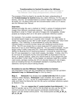
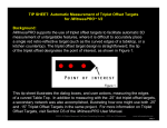
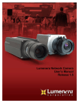
XYRectify tip sheet
This tip sheet was prepared for users with a working knowledge of
the iWitnessTM close-range photogrammetry software system
The purpose of this tip sheet is to provide the basic understanding of
using XYRectify and to present an accurate means of scaling the
XYRectify (rectified JPEG image) using a CAD diagramming software.
For this procedure, it is assumed the user has basic familiarity with the
XYRectify software. If not, please refer to the XYRectify User Manual. We
will also use the CAD Zone Quick Scene diagramming software in
combination with an originally shot oblique image that was later rectified
using the XYRectify software.
Background
Rectification is the image processing technique whereby an image taken
obliquely to a plane is converted to an equivalent ‘normal’ image of that
same plane. An easy way to picture the rectification process is to consider
the conversion of an oblique aerial image of the ground to a corresponding
vertical image. This process, which requires the establishment of a minimum
of four control points of known XY coordinates in the object plane, along with
the marking of the four corresponding image points, is carried out using
XYRectify. Following rectification, XY coordinates can be measured within
XYRectify, or with the scale-homogeneous rectified image and a CAD
diagramming program.
1. If it is at all possible, it is best to pre-calibrate the camera in iWitness,
and use the focal length & other camera parameters as the calibration
settings for XYRectify.
If the camera is NOT in the XYRectify Global Camera Database (see Figure
1), upon importing the image, Figure 2 is presented.
Figure 1
Figure 2
2. In this instance, the focal length of 26mm is simply read in XYRectify
from an image’s EXIF header tag. If the Pixel size is not correct, the user
should go to www.dpreview.com and select the Canon EOS 350D camera:
http://www.dpreview.com/reviews/CanonEOS350D/page2.asp and determine
the pixel size: In this case being: Sensor width 22.2mm / Max. Image width
3456 pixels = .0064mm.
In Figure 2, type .0064 in the “Size of image pixel” field.
3. In Figure 3, note that the camera was not calibrated, so there’s no
correction for the DISTORTION Parameters (specifically K1). For most
rectified measurements, K1 is important, but K2 and K3, as well as P1 and
P2, are not absolutely necessary. If the camera has been calibrated, then it is
best to click the “Apply corrections” box. The pixel size (mm) should be
correct relative to the c(mm) focal length (as noted in Figure 2.) NOTE: it is
always better to work with a camera that’s been calibrated using iWitness to
optimize accuracy for use in XYRectify.
Figure 3
4. At this stage the camera parameters are set up and the image will be
imported. Double-click the image thumbnail to display it.
5. Control Points:
XYRectify requires a minimum of 4 control points on a fairly planar surface
and spread out (in this example a roadway intersection.) The control points
are XY coordinates that need to be accurate. In this instance a total station
was used to measure a quantity six XY coordinates; but a total station is not
the only means of obtaining these XY coordinates, they could come from
many different sources.
Create a Control Point file using MS Notepad. Type in the name of the
control point, and then its X, and Y coordinates, separated by TABS. See
Figure 4. Save the file in your working folder.
In our example “Lwr_BE” means
“Lower Bulls-Eye” as defined by
the white X and the white
circle in the rectified image.
Figure 4
Left_CL is the end of the double
centerline on the left side (note:
the image is actually illustrated
upside down, so that is why it
appears on the right side in the
image marking process noted in
Figure 7.)
6. Click on the File + Import Control… and open the newly created control
points file.
Figure 5
7. A “Control Points” thumbnail is presented in the thumbnails located to the
left side of the screen (see Figure 10). Double-click it and the control points
dialog will be presented, as in Figure 6.
Figure 6
Click in the Label field with the “red plus” and it becomes a “yellow plus”.
Mark the corresponding location of the control point in the image and it
becomes a “green plus”. See Figure 7.
Figure 7
Do this same action for the remaining (minimum of 4) control points.
Note in Figure 7 that the “Rectified Image” in the lower left of the dialog
box displays two options, “Full Image” and “Bounded by control points”. The
default is “Full Image”. The operator can choose to rectify either the entire
original image (full image), or a portion of the original image (bounded by
control points …) equal to the area encompassed by the control points, plus a
border area of approximately 10%. In this example, we are going to leave
the tick mark on the default “Full Image”.
Figure 8 illustrates all 6 Control Points Marked, from the Control Points
Dialog Box:
Figure 8
8.
Click the “Create Image” in Figure 9.
Figure 9
The Save As dialog will now be presented. Give the resulting Projective
Transformation Image a new name; (we’ll call it “crash”.) Save it to your
working folder.
The newly created rectified image we named “crash.jpg” is now planar
rectified and an image thumbnail of it is presented above the Control
thumbnail in Figure 10. Note: the rectified image “crash.jpg” is also saved to
your working folder.
Figure 10
9. Output File from XYRectify:
The saved JPEG is accompanied by a ‘tfw’ or ‘World file’ which defines the XY
reference coordinate system for the rectified image. The TFW (ASCII text
file) is named the same name as your image; in this example case
“crash.twf” located in your working folder.
The image can now be imported into your favorite CAD package.
The TFW File created during the XYRectify Process
After marking the control points in XYRectify, a TFW “world” file is
automatically created and saved in the working folder. There are 6 lines of
numbers that represent the TFW file. The TFW six line numbers look similar
to this:
0.3190419410
0.0000000000
0.0000000000
-0.3190419410
-115.3208527345
204.8477400810
Explanation of the TFW line numbers
- LINE 1: The first line value represents the scale of any pixel in X.
- LINE 2: The second value represents the rotation in X.
- LINE 3: The third value represents the rotation in Y.
- LINE 4: The fourth value represents the scale of any pixel in Y
(negative, because Y is ‘flipped’).
- LINE 5: The fifth value represents the X value of the top-left pixel.
- LINE 6: The sixth value represents the Y value of the top-left pixel.
Using this tip sheet all that is necessary for the reader to understand is that
the first line of the TFW file represents the size of the pixel in the
Measured Units of the 4+ Control Points measured within XYRectify.
Therefore, if one knows the size of the image format, one can simply
calculate the UNIT size of the image format in width (X) or height (Y).
To acquire the XYRectify JPEG image format in pixels, simply right
clicking on the JPEG image (“Summary” tab.) See Figure 11 below:
Figure 11
In our example, the pixel size reported in the TFW file is 0.3190419410.
The numbers of pixels in the image width is 1232 (Figure 11). Therefore,
.3190419410 x 1232 (pixels) is 393.06. If the Units of Measurement from the
Control Points was Feet, then the calculation means the XYRectify image is
393.06 feet in the overall width of the image’s format.
NOTE: Pixels are dimensionally square generated as part of the XYRectify
process. For accurate CAD scaling, all that is required at this point, is to
calculate either the width of the pixels relative to the image format’s
width, or conversely the pixels height relative to the image format height.
Using the Calculation for CAD Scaling
As previously noted, we are using Quick Scene by CAD Zone as the CAD
diagramming program for this tip sheet. The Crash Zone as well as other
CAD diagramming programs offer “image scaling” functionality.
Figure 12
In Quick Scene, use the File Pull down Menu and select “Import Images”.
Figure 12
Figure 13 illustrates the XYRectify (rectified image.)
Figure 13
Quick Scene: Click on the “Bitmap scale” icon (see Figure 14.)
Figure 14
Figure 15 Quick Scene will prompt you to select (i.e., click) on the image,
followed by carefully clicking on the bottom left and right corners of the
image (see figure 16). Note: this is the image width as described earlier.
Figure 15
Figure 16
In Figure 16, notice how after clicking on the corner of the image (see left
arrow), Quick Scene places a turquoise color “marker” for the first Scale
point. The cursor on the right is illustrated as ‘pre-selecting’ the second
scale distance. Notice on the right, how the crosshair is perfectly indexed to
the corner of the image. Click it to add the second Scale Point.
Figure 17
In Figure 17, type in the proper image width distance (in our case it is
393.06’), followed by clicking “Adjust Bitmap Now”.
The XYRectify planar rectified image is now accurately scaled and ready to be
“traced” and/or any of the planar surface entities can now be measured in
the image within Quick Scene.
©2008 All Rights Reserved, DeChant Consulting Services – DCS Inc
www.iwitnessphoto.com