1
Lumenera Network Camera
User’s Manual
Release 1.8
Release 1.8
Lumenera Network Camera
User’s Manual
License Agreement (Software)
This Agreement states the terms and conditions upon which Lumenera Corporation
("Lumenera") offers to license to you (the "Licensee") the software together with all
related documentation and accompanying items including, but not limited to, the
executable programs, drivers, libraries, and data files associated with such programs
(collectively, the "Software").
The Software is licensed, not sold, to you for use only under the terms of this
Agreement.
Lumenera grants to you the right to use all or a portion of this Software provided that the
Software is used only in conjunction with Lumenera's family of products.
In using the Software you agree not to:
a) decompile, disassemble, reverse engineer, or otherwise attempt to derive the source
code for any Product (except to the extent applicable laws specifically prohibit such
restriction);
b) remove or obscure any trademark or copyright notices.
Limited Warranty (Hardware and Software)
ANY USE OF THE SOFTWARE OR HARDWARE IS AT YOUR OWN RISK. THE
SOFTWARE IS PROVIDED FOR USE ONLY WITH LUMENERA'S HARDWARE AND
OTHER RELATED SOFTWARE. THE SOFTWARE IS PROVIDED FOR USE "AS IS"
WITHOUT WARRANTY OF ANY KIND. TO THE MAXIMUM EXTENT PERMITTED BY
LAW, LUMENERA DISCLAIMS ALL WARRANTIES OF ANY KIND, EITHER EXPRESS
OR IMPLIED, INCLUDING, WITHOUT LIMITATION, IMPLIED WARRANTIES OR
CONDITIONS OF MERCHANTABILITY, QUALITY AND FITNESS FOR A
PARTICULAR PURPOSE. LUMENERA IS NOT OBLIGATED TO PROVIDE ANY
UPDATES OR UPGRADES TO THE SOFTWARE OR ANY RELATED HARDWARE.
Limited Liability (Hardware and Software)
In no event shall Lumenera or its Licensor's be liable for any damages whatsoever
(including, without limitation, incidental, direct, indirect, special or consequential
damages, damages for loss of business profits, business interruption, loss of business
information, or other pecuniary loss) arising out of the use or inability to use this
Software or related Hardware, including, but not limited to, any of Lumenera's family of
products.
Product Warranty
Lumenera Corporation warrants to the original purchaser that our cameras are
guaranteed to be free from manufacturing defects for a period of one (1) year from the
original date of purchase.
Should the unit fail during the warranty period, Lumenera will, at its option, repair or
replace the failed unit. Repaired or replaced units will be covered under warranty for the
remainder of the original one (1) year warranty period.
Copyright © 2008
Page i
Lumenera Network Camera
User’s Manual
Release 1.8
This warranty does not apply to units that, after being inspected by Lumenera, have
been found to have failed due to customer abuse, accidents, mishandling,
tampering/alteration, improper installation, improper power source, negligence, opening
of the enclosure, or if the serial number has been removed or damaged. This warranty
does not cover labor or incurred charges required in removing or installing the unit, any
business interruption, loss of profits/revenues, or any consequential damages.
Units returned to Lumenera beyond the warranty period will be repaired, if possible, and
all appropriate material and labor charges will apply.
Any returning product, specifically those being returned under warranty, must follow the
Returned Material Authorization (RMA) process. Any units being returned are to be
properly packaged (in original packing – if possible). Lumenera will not cover damage
sustained in shipping due to improper packing.
For RMA instructions, please refer to our website at www.lumenera.com.
RoHS/WEEE Compliance Statement
The Restriction of Hazardous Substances in Electrical and Electronic Equipment (RoHS)
Directive was passed into law by the European Union (E.U.). It affects manufacturers,
sellers, distributors and recyclers of electrical and electronic equipment containing lead,
cadmium, mercury, hexavalent chrome, polybrominated biphenyl (PBB) and
polybrominated diphenyl ether (PBDE). After July 1, 2006 the use of these materials will
be banned in new products sold in Europe. The RoHS Directive complements the WEEE
Directive. China is expected to adopt similar legislation within a similar timeline.
The Waste Electrical and Electronic Equipment Directive (WEEE) aims to reduce the
waste arising from electrical and electronic equipment and to improve the environmental
performance of all those involved in the life cycle of these products.
Lumenera is committed to protecting people and the environment and we are working on
identifying any materials used in our processes that could pose a potential hazard to our
employees, customers or the environment.
For this reason we are committed to have all our products comply with the RoHS and
WEEE directives. We are constantly improving our compliance with these directives. For
more information on our compliance or to track our progress please refer to our website.
Page ii
Copyright © 2008
Lumenera Network Camera
User’s Manual
Release 1.8
Table of Contents
LICENSE AGREEMENT (SOFTWARE) .................................................................................. I
LIMITED WARRANTY (HARDWARE AND SOFTWARE) ............................................................ I
LIMITED LIABILITY (HARDWARE AND SOFTWARE) ................................................................ I
PRODUCT WARRANTY ...................................................................................................... I
ROHS/WEEE COMPLIANCE STATEMENT ......................................................................... II
INTRODUCTION .............................................................................................................1
1.1
1.2
1.3
THE LUMENERA NETWORK CAMERA FAMILY ..........................................................1
WHERE TO FIND DOCUMENTATION ........................................................................1
TECHNICAL ASSISTANCE ......................................................................................2
INSTALLING THE CAMERA ..........................................................................................3
2.1
POWER SUPPLY AND CONNECTION .......................................................................3
2.1.1
2.1.2
Before You Proceed................................................................................................................ 3
Determining Your Camera Model ........................................................................................... 3
2.1.2.1
2.1.2.2
2.1.2.3
2.2
Small Format Cameras ................................................................................................................ 4
Large Format Cameras ................................................................................................................ 5
Intelligent Cameras ...................................................................................................................... 6
INSTALLATION CD-ROM ......................................................................................8
2.2.1
2.2.2
2.2.3
2.2.4
Application Software ............................................................................................................... 8
Example Code......................................................................................................................... 8
Documentation ........................................................................................................................ 8
Installation Procedure ............................................................................................................. 9
2.2.4.1
2.3
To setup and install your camera follow the steps below. ............................................................ 9
CONNECTING TO YOUR CAMERA.........................................................................10
2.3.1
2.3.2
2.3.3
2.3.4
2.3.5
2.3.6
2.3.7
Using the LeCam Client Application on the CD-ROM .......................................................... 11
Using the Camera Finder (iWitness) Application .................................................................. 11
Using Apple’s Bonjour Applet ............................................................................................... 11
Using a Dynamic IP Address ................................................................................................ 13
Using the DHCP fallback IP Address.................................................................................... 13
Using Its Link-Local IP Address ............................................................................................ 13
Setting a Static IP Address for the Camera .......................................................................... 14
2.3.7.1
Setting Your PC to a Compatible Static IP ................................................................................. 15
2.3.8 Using Apple’s QuickTime ...................................................................................................... 16
2.3.9 Using VLC Media Player ....................................................................................................... 16
2.3.10
Using Mozilla Firefox or Konqueror web browsers ........................................................... 17
2.4
2.5
2.5.1
2.5.2
TROUBLESHOOTING CAMERA CONNECTIONS........................................................18
FIRMWARE UPGRADES .......................................................................................19
Downloading Firmware ......................................................................................................... 20
Upgrading Firmware.............................................................................................................. 20
USING LECAM CLIENT................................................................................................22
3.1
3.1.1
3.1.2
3.1.3
DESCRIPTION AND USAGE ..................................................................................22
Camera Finder Tab ............................................................................................................... 23
Main Tab ............................................................................................................................... 24
Advanced Tab ....................................................................................................................... 26
UNDERSTANDING YOUR CAMERA ...........................................................................27
Copyright © 2008
Page iii
Lumenera Network Camera
User’s Manual
4.1
Release 1.8
SHUTTER TYPES ................................................................................................27
4.1.1
4.1.2
4.2
4.3
4.4
4.5
4.6
4.7
4.8
Rolling Shutter....................................................................................................................... 28
Global Shutter ....................................................................................................................... 28
SUBWINDOWING, SUBSAMPLING & BINNING .........................................................28
CAMERA MODE: STREAMING VIDEO (MJPEG) ......................................................29
SCANNING MODE ...............................................................................................30
AUTO-BRIGHTNESS CONTROL (ABC) ..................................................................30
LOCKING CONNECTOR FOR EXTERNAL POWER AND I/O ........................................31
RJ-45 ETHERNET JACK ......................................................................................32
LENS MOUNT.....................................................................................................33
4.8.1
4.8.2
4.9
4.10
4.11
Small Format and Intelligent Cameras.................................................................................. 33
Large Format Cameras ......................................................................................................... 33
ANALOG VIDEO OUTPUT .....................................................................................33
AUDIO FUNCTIONS .............................................................................................34
FACTORY RESET ...............................................................................................34
4.11.1
4.11.2
Factory Reset Switch........................................................................................................ 35
Software Reset & Recovery Commands .......................................................................... 35
4.11.2.1
4.11.2.2
Reset defaults using the Web User Interface. ............................................................................ 35
Reset defaults using a Telnet or Serial Port Connection ............................................................ 35
CONFIGURING AND USING YOUR NETWORK CAMERA.........................................37
5.1
5.2
5.3
5.4
VIDEO MANAGEMENT SUPPORT ..........................................................................37
MOUNTING THE CAMERA ....................................................................................37
LENS SELECTION ...............................................................................................38
USING DC AUTO-IRIS LENSES .............................................................................39
5.4.1
5.4.2
5.5
Connecting the DC-Iris Lens ................................................................................................. 39
Configuring Camera to Use DC-Iris Lens ............................................................................. 39
INPUT/OUTPUT AND SYNCHRONIZATION WITH EXTERNAL EVENTS ..........................40
5.5.1
5.5.2
5.6
General-Purpose Input.......................................................................................................... 40
General-purpose output ........................................................................................................ 41
USE OF FLASH OR STROBE .................................................................................42
5.6.1
5.6.2
5.7
Flash with Global Shutter ...................................................................................................... 42
Flash with Rolling Shutter ..................................................................................................... 42
SERIAL PORT CONFIGURATIONS..........................................................................43
5.7.1
5.7.2
Using the Serial Port as a Console ....................................................................................... 43
Enabling the Serial Port for Controlling Accessories ............................................................ 44
5.7.2.1
5.7.2.2
5.7.3
5.8
5.8.1
5.8.2
To Enable Sersock mode from a Telnet Console....................................................................... 44
To Enable Sersock mode from a Web Browser ......................................................................... 45
Controlling Accessories through the Serial Port ................................................................... 45
USING TELNET TO CONNECT TO THE CAMERA .......................................................45
Starting a Telnet session....................................................................................................... 45
Enabling and Disabling Telnet .............................................................................................. 46
WEB INTERFACE USER’S GUIDE ..............................................................................47
6.1
6.2
6.2.1
6.2.2
6.2.3
6.3
6.4
Page iv
OVERVIEW ........................................................................................................47
MAIN WEB INTERFACE .......................................................................................47
Admin Mode Button............................................................................................................... 48
View Mode Button ................................................................................................................. 49
Single Image Button.............................................................................................................. 49
EXPOSURE AND GAIN CONTROL ..........................................................................50
IMAGE SETTINGS CONTROL ................................................................................53
Copyright © 2008
Lumenera Network Camera
User’s Manual
Release 1.8
6.5
GEOMETRY CONFIGURATION ..............................................................................55
6.5.1
6.6
6.7
Privacy Map .......................................................................................................................... 57
DAY/NIGHT CONTROL ........................................................................................59
ALARM SETTINGS ..............................................................................................61
6.7.1
Detecting Alarm Events......................................................................................................... 62
6.7.1.1
Motion Alarms ............................................................................................................................ 62
USING A TELNET SESSION:.............................................................................................63
USING A WEB BROWSER: ...............................................................................................63
6.7.1.2
6.7.2
6.7.2.1
6.7.2.2
6.7.2.3
6.8
6.8.1
6.8.2
6.8.3
6.9
6.10
6.11
6.12
6.13
6.14
6.15
6.16
6.17
6.18
GPIO Input Alarms ..................................................................................................................... 64
Alarm Event Notifications ...................................................................................................... 65
Email Alarm Notifications ........................................................................................................... 65
FTP Alarm Notifications.............................................................................................................. 65
UDP Alarm Notifications............................................................................................................. 65
STREAMING CONTROL ........................................................................................67
FTP Streaming Video............................................................................................................ 67
RTP/RTSP Video Streaming................................................................................................. 69
Analog Output ....................................................................................................................... 70
NETWORK SETTINGS ..........................................................................................70
DATE/TIME CONFIGURATION ...............................................................................71
PASSWORDS CONFIGURATION ............................................................................72
WATCHDOG CONTROL .......................................................................................73
FIRMWARE SETTINGS .........................................................................................74
REBOOT CAMERA CONTROL ...............................................................................74
IMAGE DEFAULTS SETTINGS ...............................................................................74
SAVE SETTINGS CONTROL..................................................................................75
LOAD SETTINGS CONTROL .................................................................................75
DOCUMENTATION...............................................................................................75
GLOSSARY ..................................................................................................................77
Copyright © 2008
Page v
Lumenera Network Camera
User’s Manual
Release 1.8
List of Figures
Figure 2-1 Le-Series Standard-Format Camera Back Panel ..........................................5
Figure 2-2 Le-Series Large Format Back Panel ..............................................................6
Figure 2-3 Li-Series Camera Back Panel ........................................................................7
Figure 2-4 Output from the Camera Finder Application .................................................11
Figure 2-5 Bonjour Toolbar in Internet Explorer 7..........................................................12
Figure 2-6 Selecting a Specific Camera Using the Bonjour Toolbar..............................13
Figure 3-1 LeCam Client's Camera Finder Window.......................................................22
Figure 3-2 LeCam Client Main Tab................................................................................25
Figure 3-3 LeCam Client Capture Dialog Box................................................................26
Figure 4-1 Diagram of the 10-Pin Locking Power Connector.........................................31
Figure 4-2 RJ45 Connector Pin out ...............................................................................32
Figure 4-3 Web Browser Option to Enable/Disable the Analog Output .........................33
Figure 5-1 Input (GPI) Circuit.........................................................................................40
Figure 5-2 Output (GPO) Circuit ....................................................................................42
Figure 6-1 Main Web Page of Network Camera User Interface.....................................47
Figure 6-2 Buttons on Main Web Page..........................................................................48
Figure 6-3 Links to Menus on the Admin Mode Tab ......................................................48
Figure 6-4 Exposure and Gain Controls ........................................................................50
Figure 6-5 Le045 and Li045 Exposure/Gain Controls....................................................51
Figure 6-6 Lens Control Options for 35mm Lenses In Exposure/Gain Controls ............51
Figure 6-7 White Balance Section of Exposure/Gain Controls ......................................52
Figure 6-8 Auto Window Section of Exposure/Gain Controls ........................................52
Figure 6-9 Image Settings Controls ...............................................................................53
Figure 6-10 Image Settings Controls for Le045 and Li Series .......................................54
Figure 6-11 Geometry Settings......................................................................................55
Figure 6-12 Binning/Subsampling Options In Geometry Settings..................................55
Figure 6-13 Geometry Grid............................................................................................56
Figure 6-14 Image Illustrating the Privacy Map Grid......................................................57
Figure 6-15 Image with Privacy Map Activated..............................................................58
Figure 6-16 Day/Night Settings......................................................................................59
Figure 6-17 Controls Included In the Alarms Page on the Web Interface......................61
Figure 6-18 Image With Show Motion Detection Regions Feature Active .....................64
Figure 6-19 Image with the Show Motion Detected Feature Active ...............................64
Figure 6-20 Streaming Control in Web Interface ...........................................................67
Figure 6-21 Network Settings ........................................................................................70
Figure 6-22 Date/Time Settings.....................................................................................71
Figure 6-23 Passwords Dialog.......................................................................................72
Figure 6-24 Watchdog Menu .........................................................................................73
Figure 6-25 Firmware Menu ..........................................................................................74
Page vi
Copyright © 2008
Lumenera Network Camera
User’s Manual
Release 1.8
List of Tables
Table 2-1 Lumenera Network Camera Models ................................................................4
Table 2-2 Le-Series Standard-Format Power and Interface Connections .......................5
Table 2-3 Le-Series Large-Format Power and Interface Connections.............................6
Table 2-4 Li-Series Power and Interface Connections ....................................................7
Table 4-1 Shutter Types by Camera Model ...................................................................27
Table 4-2 Subsampling and Binning Modes ..................................................................29
Table 4-3 Detailed Pin-Out of Locking Power, I/O & Rs232 Connector.........................31
Table 4-4 Mic In Audio Specifications............................................................................34
Table 4-5 Line Out Audio Specifications........................................................................34
Table 4-6 Configuration of 3.5 mm Stereo Plug.............................................................34
Table 5-1 Optical Format for Each Camera Model ........................................................38
Table 5-2 Input (GPI) Opto-Isolator Parameters............................................................41
Table 5-3 General Purpose Output Modes Set Using output_select.......................41
Table 5-4 Output (GPO) Opto-Isolator Parameters .......................................................42
Copyright © 2008
Page vii
Release 1.8
Lumenera Network Camera
User’s Manual
1
Introduction
1.1 The Lumenera Network Camera Family
Lumenera Network Cameras are designed to satisfy both general-purpose and
high-end surveillance applications, delivering outstanding image quality. The
cameras use on-board JPEG compression to deliver high quality images over a
standard 10/100baseT Fast Ethernet connection. In video surveillance
applications, Lumenera Network cameras work with an extensive list of thirdparty NVR/DVR software and hardware to provide complete video management
solutions. Support for different camera models is kept uniform using a common
Application Programming Interface (API) to the greatest extent possible.
Lumenera’s product line is unique in its breadth, with resolution range from VGA
to 11-megapixels and a choice of several CMOS and CCD image sensors in both
color and monochrome types. Most models use C/CS- mount lenses commonly
found in CCTV and factory automation, and are available with an integrated
day/night filter option for use with active-infrared illumination. For demanding
applications such as low-light surveillance, traffic enforcement, and industrial
process monitoring, Lumenera provides high-sensitivity, low-noise CCD’s with
global shutter. Large-format models use off-the-shelf 35-mm motorized lenses to
provide exceptional image quality and sensitivity.
The Li-series intelligent network cameras provide additional features including
embedded rules-based video content analysis, audio input and output, analog
video output for use in installation, and standard Power over Ethernet (PoE).
The description of the online Graphical User Interface (GUI) to the cameras and
the API applies specifically to the camera firmware version 1.8. Extensions
specific to the Li series intelligent cameras refer to firmware version 2.3.
1.2 Where to Find Documentation
All camera documentation can be found in the C:\Program Files\Lumenera
Corporation\Documentation folder. The documentation that is provided includes
this manual, the Camera API manual, camera Application Notes and White
Papers.
Copyright © 2008
Page 1
Lumenera Network Camera
User’s Manual
Release 1.8
1.3 Technical Assistance
If you need assistance with the installation or use of the software, or, if you need
help with general camera operation, please contact the Technical Assistance
Centre (TAC) via email at:
[email protected]
or by phone at +1-613-736-4077 (press 1 from the auto attendant).
To obtain the latest software release and other technical information you may
visit our technical support website at:
http://www.lumenera.com/support/index.php
Our support website contains technical information available to the general public
such as Frequently Asked Questions (FAQ’s). For our Lumenera customers we
provide a Knowledge Base with more product specific solutions and a Download
Centre for customers to obtain the most recent software releases.
As a customer, you will need to provide the TAC with some basic information to
gain access to the customer Knowledge Base and the Download Centre. Please
provide the following details via email to [email protected] to obtain a user
name and password:
•
Your name, Company Name, address and telephone number
•
Your camera model and serial number
•
Your purchase information (e.g. did you purchase from an OEM or
distributor?)
Upon providing the above information, you will receive your access information
via email from a TAC representative.
Page 2
Copyright © 2008
Lumenera Network Camera
User’s Manual
Release 1.8
2
Installing the Camera
2.1 Power Supply and Connection
This section describes the electrical connections for power and auxiliary
functions of the Lumenera Network Cameras.
Power, general purpose input/output (GPIO), DC auto-iris connections, and
RS232 serial communications can all be found on the back panel of the camera.
In addition, new Li-series intelligent cameras provide connections for BNC analog
video output and a two-way audio jack.
2.1.1 Before You Proceed
Please observe the following precautions to prevent damage and protect your
warranty.
•
Power requirements vary depending on the camera model. Please take
care to follow all power requirements marked on the camera case and
stated in this manual.
•
Wiring to the unit must be in compliance with electrical codes.
•
Do not ground either terminal of an external power supply to the camera at
any location, otherwise permanent damage may result. If you are using an
AC power supply, it must be floating and not tied to ground.
•
Do not apply excessive voltage or current to the auxiliary connections (DC
iris, GPIO, RS232, analog video out, audio in/out, etc.).
•
Use only Power over Ethernet injectors or switches that are certified as
IEEE 802.3af compliant.
•
Maintain temperature from -10 ºC to +50 ºC (14 ºF to 122 ºF) during
operation.
•
Maintain relative humidity from 5% to 95% non-condensing during
operation.
2.1.2 Determining Your Camera Model
Please locate your camera model in the table below and proceed to the page
indicated for step-by-step installation instructions.
Copyright © 2008
Page 3
Lumenera Network Camera
User’s Manual
Release 1.8
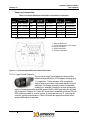
Table 2-1 Lumenera Network Camera Models
Model
Resolution
megapixels
Video
analytics
option
DayNight
option
Lens mount1
Section of
this Guide
Le045
0.3 (NTSC)
No
YES
CS
2.1.2.3
Li045
0.3 (NTSC)
YES
YES
CS
2.1.2.3
Le075
0.3 (VGA)
No
YES
CS
2.1.2.1
Le165
1.4 (SXGA+)
No
YES
CS
2.1.2.1
Li165
1.4 (SXGA+)
YES
YES
CS
2.1.2.3
Le175
1.3 (SXGA)
No
YES
CS
2.1.2.1
Li175
1.3 (SXGA)
YES
YES
CS
2.1.2.3
Le259
2.1 (HD1080)
No
No
Canon EF
2.1.2.2
Le275
1.9 (UXGA)
No
YES
CS
2.1.2.1
Le375
3.1 (QXGA)
No
YES
CS
2.1.2.1
Le575
5.0
No
YES
CS
2.1.2.1
Le11059
10.6
No
No
Canon EF
2.1.2.2
1 Use Lumenera part C-to-CS mount 5-mm adapter to mount a C-mount lens on a CS-mount camera
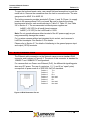
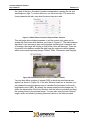
2.1.2.1 Small Format Cameras
The Le-series standard-format Network cameras offer an
industry-leading selection of CMOS and CCD imagers
ranging from VGA resolution to 5 megapixels. Megapixel
CMOS imagers provide unsurpassed image detail. For
challenging applications such as highway traffic and night
surveillance, our low noise, high sensitivity, global-shutter
CCD’s are unique among IP CCTV products. All standard-format Le-series
cameras are also available with a field-proven true day/night option. The daytime
infrared-cut filter guarantees accurate color. The night time clear glass
maximizes sensitivity and enables the camera to be used with active infrared
lighting.
Page 4
Copyright © 2008
Lumenera Network Camera
User’s Manual
Release 1.8
Power and connectivity
Table 2-2 Le-Series Standard-Format Power and Interface Connections
Model
Le075
9-24 V AC/DC
Max.
power
draw
4W
Le165
Le175
Le275
9-24 V AC/DC
9-24 V AC/DC
9-24 V AC/DC
5W
4W
4W
Use Le902
Use Le902
Use Le902
1 in, 1 out
1 in, 1 out
1 in, 1 out
Male DE-9
Male DE-9
Male DE-9
10/100 baseT
10/100 baseT
10/100 baseT
Le375
9-24 V AC/DC
4W
Use Le902
1 in, 1 out
Male DE-9
10/100 baseT
Le575
9-24 V AC/DC
4W
Use Le902
1 in, 1 out
Male DE-9
10/100 baseT
Power input1,2
4-wire DC
auto-iris
Use Le902
I/O
1 in, 1 out
RS232
Male DE-9
Network
10/100 baseT
1 Use Lumenera part Lu8401 110-240 VAC 50/60 Hz IN, 24 VDC/1A OUT universal supply for indoor use.
2 IEEE 803.af Power over Ethernet option available.
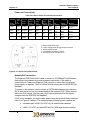
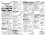
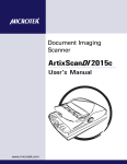
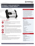
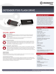
1 - Ethernet RJ45 jack
2 - 10-pin locking power, input-output,
and dc-iris connector
3 – RS232 serial port
4 – Factory reset switch
Figure 2-1 Le-Series Standard-Format Camera Back Panel
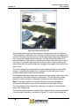
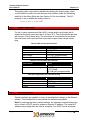
2.1.2.2 Large Format Cameras
The Le-series large format Network cameras offer
advanced high-resolution CCD imagers ranging up to
11 megapixels. These cameras offer exceptional
support where panoramic views and digital zoom are
essential. The image geometry is also configurable,
enabling, for example, imaging in a wide rectangular
region of interest spanning multiple lanes of traffic, while excluding the sky and
the foreground. Support for Canon EF-mount and compatible motorized 35-mm
SLR lenses provides for remote control of focus and iris over IP, reducing the
need for periodic maintenance. Canon IS lenses are supported where active
image stabilization is required.
Copyright © 2008
Page 5
Lumenera Network Camera
User’s Manual
Release 1.8
Power and connectivity
Table 2-3 Le-Series Large-Format Power and Interface Connections
Power
input1
Max.
power
draw
4-wire DC
auto-iris
I/O
RS232
Network
Le259
12 VDC
10 W
Use Le902
1 in, 1 out
Male DE-9
10/100 baseT RJ-45
Le11059
12 VDC
15 W
Use Le902
1 in, 1 out
Male DE-9
10/100 baseT RJ-45
Model
1 Use Lumenera part Lu8501 110-240 VAC 50/60 Hz IN, 12 VDC/2A OUT universal supply for indoor use.
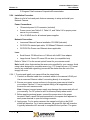
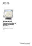
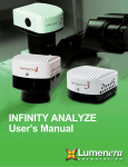
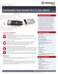
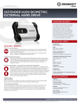
1 - Ethernet RJ45 jack
2 - 10-pin locking power, input-output, and dciris connector
3 – RS232 serial port
4 – Factory reset switch
Figure 2-2 Le-Series Large Format Back Panel
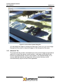
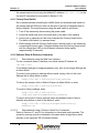
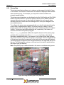
2.1.2.3 Intelligent Cameras
The Li-series Network camera family is DSP-based to
provide optional ObjectVideo™ OnBoard™ video analytics.
Video analytics options are indicated by -OV1, -OV2, and
-OV3 suffixes to the camera part numbers, where -OV3
indicates the highest functionality. Camera models include
the following:
Page 6
•
Le045 / Li045: ultra-wide dynamic range for capturing high-contrast
scenes
•
Li165: state-of-the-art 1.4 megapixel CCD camera for high sensitivity
•
Li175: 1.3 megapixel CMOS camera
Copyright © 2008
Lumenera Network Camera
User’s Manual
Release 1.8
Power and Connectivity
Table 2-4 Li-Series Power and Interface Connections
Model
Le045
Li045
Li165
Li175
IEEE
802.3
af
PoE
External
power
option1
Max.
power
draw
Analog
video
OUT
Audio
IN/OUT
4-wire
DC
iris
I/O
RS232
Network
1 in
Terminal
10/100 base T
1 out
block
RJ-45
1 in
Terminal
10/100 base T
YES
24 VDC
6W
BNC
Yes
Yes
1 out
block
RJ-45
1 in
Terminal
10/100 base T
YES
24 VDC
6W
BNC
Yes
None
1 out
block
RJ-45
24 V
1 in
Terminal
10/100 base T
YES
6W
BNC
Yes
Yes
AC/DC
1 out
block
RJ-45
1 Use Lumenera part Lu8401 110-240 VAC 50/60 Hz IN, 24 VDC/1A OUT universal supply for indoor use.
YES
24 VDC
6W
BNC
Yes
Yes
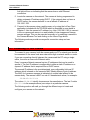
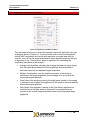
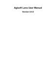
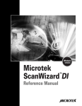
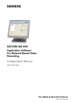
1 - Ethernet/PoE RJ45 jack
2 - 10-pin locking power & input-output connector
3 - Analog VIDEO output
4 – 4-conductor DC-auto-iris socket
5 - Audio jack for line out and mic in
Figure 2-3 Li-Series Camera Back Panel
Network/PoE connection
The Ethernet POE RJ-45 jack is used to connect a 10/100baseT Fast Ethernet
data cable to the camera to provide a network connection. If the cable is
connected to a Power over Ethernet (PoE) injector or switch then no external
power supply is required. The PoE device should comply with the IEEE 802.3af
standard.
To power on the camera, simply connect a CAT5e cable between the camera’s
RJ-45 jack and a port on your network/switch that supports PoE. When working
with a non-PoE switch, you may use a PoE injector provided that the injector
complies with the IEEE 802.3af standard.
If PoE is not available, you must supply power using the terminal block connector
(item 2 in Figure 2-3 above). The recommended universal power supplies are:
•
Lumenera part Lu8401 (24 VDC) for all small-format cameras
•
Lu8501 (12 VDC) for the Le259 and Le11059 large-format cameras.
Copyright © 2008
Page 7
Lumenera Network Camera
User’s Manual
Release 1.8
Note: Be sure to apply the correct polarity on Li-series cameras that specify 24V
DC external power supplies.
The green link light will pulse during the camera power-up sequence. When the
camera is finished booting, the green link LED will be lit continuously whenever a
working network connection is available.
You may locate the camera on your network using either the LeCam Client or the
Lumenera Camera Finder (iWitness.exe) applications provided on the CD-ROM
that comes with your camera. Detailed camera settings can be controlled from a
web browser based user interface. Refer to Section 2.4 for other options to
determine your camera’s IP address.
2.2 Installation CD-ROM
Lumenera Network cameras do not require any special-purpose software. You
can access any camera through a web browser by entering the camera’s IP
address. The CD-ROM that comes with your camera provides additional
applications, tools and documentation to help you use and understand your
Network camera.
The following files are installed when you run the installation program located on
the CD-ROM.
2.2.1 Application Software
The LeCam Client demonstration application is provided to quickly find and
control Lumenera Network cameras on your network. The application can be
found in the following installation path:
C:\Program Files\Lumenera Corporation\
A shortcut to this application is added to the Start Menu at the location selected
during installation. The default location is:
Start > Programs > Lumenera
2.2.2 Example Code
The default location for example code is:
C:\Program Files\Lumenera Corporation\Sample Code
The source code consists of a complete Microsoft Visual C++ 6.0 project. The
libraries are also compatible with Visual Basic, Visual C# and Borland C++
Builder.
2.2.3 Documentation
Documentation consisting of this User’s Manual, the API Reference Manual and
the latest available Application Notes and White Papers are installed in:
Page 8
Copyright © 2008
Lumenera Network Camera
User’s Manual
Release 1.8
C:\Program Files\Lumenera Corporation\Documentation
2.2.4 Installation Procedure
Below is a list of tools and parts that are necessary to setup and install your
Network Camera.
Power Connections:
• 10-terminal power & I/O connector (included)
•
Power source (see Table 2-2, Table 2-3, and Table 2-4 for proper power
source for your camera)
•
18 to 28 AWG wire for all external power supplies
Network Connection:
• Lumenera Ethernet Camera Installation CD-ROM (included)
•
CAT5/CAT5e twisted pair cable, 10/100baseT Ethernet connection
•
CAT5/CAT5e Power over Ethernet where applicable
Lens:
• Small-format: CS-Mount lens or C-Mount with Lu901 5mm adaptor
•
Large-format: Canon EF-mount 35 mm lens (or compatible lens)
Refer to Table 2-1 for the correct optical format for your camera model.
Note: Install a lens that matches the sensor size specified for your camera. Avoid
using a lens designed for a smaller sensor (e.g. 1/3” format lens on a 1/2" format
sensor) as undesirable vignetting (corners will be darker than the rest of the
image) will occur.
2.2.4.1 To setup and install your camera follow the steps below.
1. Connect an Ethernet cable from a network switch to the camera’s RJ45 port.
Use a crossover Ethernet cable if connecting directly to a computer.
2. Ensure your power source conforms to the proper power source listed for
your camera. Section 2.1 has a complete listing of all supported power
sources for each camera model.
Note: Using an incorrect power supply may damage the camera and will void
your warranty. For DC power be sure to observe polarity where noted.
3. Before applying external power, connect the power wires to the power
terminals. Insert a small flat-head screwdriver in the square hole adjacent to
each power terminal to open its locking connector.
4. Apply power. For Le series cameras, the orange boot light on the RJ45
socket will be active. For Li series cameras, the green link light will be active.
It typically takes about 45 seconds to complete the boot process. The green
Copyright © 2008
Page 9
Lumenera Network Camera
User’s Manual
Release 1.8
link light will turn on indicating that the camera has a valid Ethernet
connection.
5. Locate the camera on the network. The camera is factory programmed to
obtain a dynamic IP address using DHCP. If the network does not have a
DHCP server, the camera defaults to use a fallback IP address of
192.168.1.222.
6. Connect to the camera using a web browser or by using the LeCam Client
application included with the CD-ROM which is described in more detail in
Chapter 3. Use the camera’s IP address (e.g. http://192.168.2.183) to connect
to the on-camera web server in a web browser to view images and change
camera settings. This can be executed manually or by selecting a camera in
the Camera Browser Tool and clicking on the Home Page button.
The following sections provide more specific connection setup and use
information.
2.3 Connecting To Your Camera
To connect to your camera, both the camera and your PC’s network port should
be connected to the same local area network through a network switch or router.
If you are connecting directly between the camera and the PC using a single
cable, it must be a cross-over Ethernet cable.
Every Lumenera Network camera has two IP addresses that can be used to
access it. The first IP address is configurable to either a static IP address or a
dynamic IP address that is acquired from a DHCP server.
The second IP address is the pre-determined, non-configurable link-local IP
address which is based on the camera’s MAC (Media Access Control) address.
The MAC for Lumenera cameras is indicated on a white label affixed to the
camera body. The camera’s MAC is a set of 6 hexadecimal values, for example:
00:0B:E2:0D:12:CD
The values 00:0B:E2 identify Lumenera as the manufacturer. The last 3 octets
(0D:12:CD in the example above) are unique to a particular camera.
The following section will walk you through the different ways to locate and
configure your camera on the network.
Page 10
Copyright © 2008
Lumenera Network Camera
User’s Manual
Release 1.8
2.3.1 Using the LeCam Client Application on the CD-ROM
The LeCam Client application allows you to find any Lumenera Network camera
that is on the same sub-net as the computer running it. It is based on the
ZeroConf protocol similar to Apple’s Bonjour application. This application is
explained in more detail in Chapter 3.
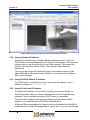
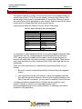
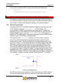
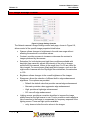
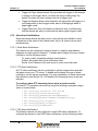
2.3.2 Using the Camera Finder (iWitness) Application
The Camera Finder application allows one to locate cameras on the local
network. Clicking on the Refresh button will update the list. Each camera is
identified by name, MAC address, primary IP address, and link-local IP address.
Each row in the table represents a particular camera that can be selected using
the mouse on your PC. Once your camera selection has been made, the Preview
button provides a live view of the camera in a separate window together with
statistics on the video streaming data rate. Clicking on the Home Page button will
open the camera’s full user interface in a web browser.
Figure 2-4 Output from the Camera Finder Application
2.3.3 Using Apple’s Bonjour Applet
Apple Macintosh computers that are equipped with Bonjour (formerly called
Rendezvous) may access the camera by name. It uses the ZeroConf protocol to
find and query the camera’s information. The name consists of the camera model
name plus the last 6 digits of the camera’s MAC address
On a Windows PC, the Network camera may be discovered by using Apple’s
Bonjour applet to search for local web servers. You can get more information on
the Bonjour applet on Apple’s website (www.apple.com/bonjour). A plug-in for
Microsoft Internet Explorer for Windows can be downloaded from the same web
site, or you may use the installation file included on the CD-ROM in the following
path:
C:\Program Files\Lumenera Corporation\Integration\3rdParty
An example ZeroConf camera name for the LE175 1.3 megapixel camera with a
MAC address of 00:0B:E2:0D:12:CD is LE175-0D12CD. The camera can be
located by entering the URL http://le175c-0d12cd.local/ in a web browser. This
Copyright © 2008
Page 11
Lumenera Network Camera
User’s Manual
Release 1.8
default URL will change only if the camera name is edited in the Network section
of the Admin Mode tab of the camera’s web interface.
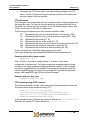
Once you have installed the Bonjour applet, there will be a link to it within your
Internet Explorer web browser, as shown in Figure 2-5.
Figure 2-5 Bonjour Toolbar in Internet Explorer 7
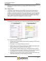
By selecting this link, a new frame will appear on the left side of the browser
window. In this frame, you will see all network devices that can respond to the
ZeroConf requests including all accessible Lumenera Network cameras, as
shown in Figure 2-6.
To select a camera from this list, simply double-click it in list provided. The
camera’s main webpage will appear in the right part of the browser.
Page 12
Copyright © 2008
Lumenera Network Camera
User’s Manual
Release 1.8
Figure 2-6 Selecting a Specific Camera Using the Bonjour Toolbar
2.3.4 Using a Dynamic IP Address
As a factory default setting, Lumenera Network cameras are set to look for a
DHCP server to dynamically assign an IP address to the camera. This makes the
cameras easy to use during set-up on most office networks. The camera can
then be found using the LeCam Client or the Camera Finder (iWitness)
applications.
You can get the assigned IP address by going to the Network section on the
Admin Mode tab on the camera’s web interface. It is located in the IP address
field on this web page.
2.3.5 Using the DHCP fallback IP Address
If no DHCP server is located at boot time, the camera will attempt to use a
fallback IP address of 192.168.1.222.
2.3.6 Using Its Link-Local IP Address
The link-local IP address can be useful for locating your camera initially, for
identification and location for network administrators, and for troubleshooting
purposes. This is especially true when a DHCP server is unavailable.
The link-local IP address of the camera is derived from the camera’s MAC
address. It is located within the 169.254.93.0 address block.
A Microsoft Excel spreadsheet for finding the link-local address from the MAC is
available from the online Knowledge Base or can be sent to you by email through
Copyright © 2008
Page 13
Lumenera Network Camera
User’s Manual
Release 1.8
a request our TAC group at [email protected], by providing your camera’s
unique MAC address.
To calculate the link-local address of your camera yourself, use the following
equation which is based on the last 4 hexadecimal digits (last 2 octets) of the
camera’s MAC address:
169.254.[(93+A)%256].[B]
where,
% = take the remainder of the division of (93 + A) / 256
A = the 3rd and 4th last hexadecimal digits, and B = the last two hexadecimal
digits.
For example, consider a camera with the following MAC address:
00:0B:E2:0B:01:6D
A = 1 (01 hexadecimal)
B = 109 (6D hexadecimal)
The camera’s link-local IP address is 169.254.94.109.
l set use_link_local=0
Refer to Sections 5.7 and 5.8 for information on telnet and serial consoles.
To disable the link-local address in a web browser use:
http://169.254.94.109/cgi-bin/set?use_link_local=0
Be sure to substitute the actual camera IP address for the example shown. To
apply the change, you must save settings to store the updates in the non-volatile
memory, and then reboot the camera. Links to the Save Settings and Reboot
Camera options are available in the Admin Mode tab in the camera’s web
interface. You can also use API functions to save and reboot in a telnet or serial
console:
l save_settings
l reset
or web browser/CGI instruction:
http://169.254.94.109/cgi-bin/save_settings
http://169.254.94.109/cgi-bin/reset
After 30-45 sec., the camera will complete booting. It will not reappear in the
same browser window, since you must now specify a valid IP address other than
the link-local address.
2.3.7 Setting a Static IP Address for the Camera
In some cases, it may be beneficial to assign a static IP address to the camera
so that it is maintained regardless of what else happens on the network. This
may be the case when using an Network Video Recorder (NVR) where you want
Page 14
Copyright © 2008
Release 1.8
Lumenera Network Camera
User’s Manual
it to always look for the camera at a specific IP. This section describes how you
can set a static IP address for the camera.
Once communication with the camera is established using the web browser
interface, it is easy to set the IP address of the camera.
1. Go to Admin Mode tab on the camera’s web interface. Click on the link for the
Network menu. Refer to Section 6.9 for detailed information on using the
Network settings.
2. Click the option button to set DHCP off.
3. Enter the new static IP address for the camera, e.g. 192.168.2.78.
4. Enter the new netmask, e.g. 255.255.255.0.
5. The gateway should be optional. An example is 192.168.2.1. Consult your
Network Administrator for more information on what this value should be.
6. Click on the button to Change network settings.
7. Instructions will appear telling you to save settings and reboot to put the
changes into effect. To do this, click on the Save Settings link and then click
OK when prompted to proceed. You will need to wait 5-10 seconds for the
confirmation message to appear in your web browser and click OK again and
then click on the Reboot Camera link. You can also use API functions to save
settings in a telnet/serial console:
l save_settings
or in a web/CGI command:
http://169.254.94.109/cgi-bin/save_settings
To reboot the camera with the new network settings, substitute reset for
save_settings in the commands shown above. After 30-45 sec., the camera
will complete the boot process. It will not reappear in the same browser window,
since you must now enter the new camera IP address (192.168.2.78 in this
example).
2.3.7.1 Setting Your PC to a Compatible Static IP
1. On a Windows PC, go to the Windows Control Panel and double-click on the
Network Connections icon.
2. Double-click on Local Area Connection. In the Local Area Connection Status
window, click on the Properties button.
3. In the Local Area Connection Properties window, select Internet Protocol
(TCP/IP) then click on the Properties button.
4. In the Internet Protocol (TCP/IP) Properties window, click on the option button
to Use the following address. Enter an IP address that is not currently in use
that is on the same subnet as the Network cameras, for example, a private
Copyright © 2008
Page 15
Lumenera Network Camera
User’s Manual
Release 1.8
address 192.168.2.11 (or 169.254.1.1 for a link-local connection using a
cross-over cable between the PC and the camera).
5. Enter a netmask value of 255.255.255.0. You may optionally enter a
gateway address such as 192.168.2.1, but it is typically not necessary. If
you are using link-local addresses for the camera and PC (e.g.
169.254.x.x) specify the netmask as 255.255.0.0.
6. Click OK twice, and Close to exit the 3 open windows and apply changes.
Now that the Network cameras and the PC have their IP addresses on the same
subnet, the cameras will be accessible by the computer.
2.3.8 Using Apple’s QuickTime
The QuickTime media player from Apple is easy to use with RTP/RTSP
streaming video from the camera. To enable RTP, use the camera web interface,
select Admin Mode and then the Streaming link. Check the box next to the
RTP/RTSP option. The related API property is rtp_enable. In a Telnet/Serial
console, type the following:
l set rtp_enable=1
The equivalent HTTP CGI command is:
http://192.168.1.222/cgi-bin/set?rtp_enable=1
To play in QuickTime, select File and then Open URL. Enter the URL using the
following format:
rtsp://192.168.1.222
Be sure to specify the actual IP address of your camera. You may have to press
the play button in QuickTime to start the streaming video.
Note: The QuickTime player does not support image widths greater than 2048.
2.3.9 Using VLC Media Player
The VLC media player from VideoLAN (www.videolan.org) is a streaming media
application suitable for use with the Lumenera Network cameras. VLC requires
camera firmware version 1.6.0.0 or greater.
In VLC Media Player, select File|Open Network Stream menu option to start a
connection to the camera. Select the Network tab, choose the HTTP option. If
your camera uses the DHCP fallback IP address of 192.168.1.222, for
example, you would enter the following in the "URL" field:
http://192.168.1.222/cgi-bin/nph-video?
type=multipart/x-mixed-replace
To pull images from earlier in the buffer, modify this link by including the optional
start and archive parameters to the video command in the API. The value
of archive must be true (1) for the start parameter to take effect. Use a
Page 16
Copyright © 2008
Lumenera Network Camera
User’s Manual
Release 1.8
negative value for start to specify how many frames back in the ring buffer you
wish to begin the MJPEG video stream. This option will only work if all of the
images requested are present in the buffer. A CGI example is provided below:
http://192.168.1.222/cgi-bin/nph-video?
type=multipart/x-mixed-replace&
start=-100&archive=1
If you want to record, in the same Open dialog box, on the Network tab, look at
the Advanced Options area at the bottom. Check the Stream/Save check box
and then hit the Settings button. The Stream Output dialog box is displayed. In
the Output section, check Play locally if you wish to view live images while you
record. Also check File and Browse to the correct directory and then enter a file
name including the extension, e.g. newclip.asf or newclip.mov.
To create a file for later play back in Windows Media Player, you can use the
following options:
•
Encapsulation Method - ASF (Windows Media standard)
•
Transcoding options - check Video codec, select DIV3 from pull-down,
select bit rate 1024 (default) from the pull-down menu.
Once you exit the dialogs and click on the play button, the camera’s video stream
will be recorded to the .ASF file name provided.
To create a file for later play back in QuickTime, you can use the following:
•
Encapsulation Method – MOV
•
Transcoding options - check Video codec, select DIV3 from pull-down,
select bit rate 1024 (default) from pull-down.
Note: One potential issue with VLC is that if you go back and edit the file name in
VLC, it will not take effect. So it is recommended to use a single file name and
keep overwriting it, as long as you are sure to rename the specific ASF or MOV
files using Windows Explorer when you want to keep them.
VideoLAN provides an ActiveX control that can be incorporated into your custom
applications. Feel free to contact VideoLAN for more information on this ActiveX
control and to acquire it at www.videolan.org for details.
2.3.10 Using Mozilla Firefox or Konqueror web browsers
Some web browsers such as Mozilla Firefox and Konqueror offer support for
MJPEG streaming and display. This feature is not present in Internet Explorer.
To use this feature, simply enter a URL in the address line of the web browser.
The format of the URL is the same as that describe in Section 2.3.9
Copyright © 2008
Page 17
Lumenera Network Camera
User’s Manual
Release 1.8
2.4 Troubleshooting Camera Connections
The LeCam Client application from the installation CD-ROM will locate local
Network cameras, allow you to view images from them and open their web
interfaces. Below is a quick list of steps that will help you communicate with your
cameras more easily:
1. Verify that the camera is powered on and is connected to the network cable.
A green link light on the Ethernet port indicates an active network connection.
Verify that your computer and the camera are physically connected to the
same network switch or router.
2. Open the LeCam Client application to find your camera on the network. If it is
not presented in the list of available cameras, you may need to modify your
Network properties to see it from this network. Chapter 3 provides more
information on how to find and use the LeCam Client application with your
Network camera.
3. Ping the camera. This will check to see that your computer can communicate
to the camera over your network. On a Windows PC, go to the Start menu,
select Run… and enter cmd in the Run dialog. This opens a Command
Prompt window with a command prompt such as:
C:\Documents and Settings\user>
At the prompt, type ping followed by the camera IP address and press the
enter key:
ping 192.168.1.222
The ping command will attempt to communicate with the specified IP address
to a total of four attempts, and provide a report each time. A communication
failure is indicated by the response:
Request timed out.
Successful communications create a response of the format:
Reply from 192.168.1.222: bytes=32 time=1ms TTL=63.
4. Check that the PC’s IP address is compatible with that of the camera. To
check a Windows PC’s IP address, go to Network Connections, right-click on
the Local Area Connection and select the Properties menu option. The LAN
Properties dialog will display a list below the text “This connection uses the
following items:” The option Internet Protocol (TCP/IP) is normally displayed
near the bottom of the list. Select the Internet Protocol (TCP/IP) item and click
on the Properties button. To provide a route to the camera, the TCP/IP
properties of your PC should be similar to the camera’s Network settings.
Ensure that the computer IP address is on the same subnet as the Network
camera’s IP address (e.g. both camera and PC have 192.168.22.xxx IP
address with netmask 255.255.255.0). Refer to Sections 2.3.7 and 2.3.7.1
for details of the camera’s Network menu.
Page 18
Copyright © 2008
Lumenera Network Camera
User’s Manual
Release 1.8
5. Reset your Network Interface Card. For a Windows PC, go to the Start Menu,
Control Panel. Double-click Network Connections, then right-click on Local
Area Connection. Select either Repair or Disable menu options. Right click
and select Enable menu option after using the Disable option. This should fix
most common network problems, such as an intermittent physical connection.
6. Check that the PC’s IP address is compatible with that of the camera. To
check a Windows PC’s IP address, go to Network Connections, right-click on
the Local Area Connection and select the Properties menu option. The LAN
Properties dialog will display a list below the text “This connection uses the
following items:” The option Internet Protocol (TCP/IP) is normally displayed
near the bottom of the list. Select the Internet Protocol (TCP/IP) item and click
on the Properties button. To provide a route to the camera, the TCP/IP
properties of your PC should be similar to the camera’s Network settings.
Ensure that the computer IP address is on the same subnet as the Network
camera’s IP address (e.g. both camera and PC have 192.168.22.xxx IP
address with netmask 255.255.255.0). Refer to Sections 2.3.7 and 2.3.7.1
for details of the camera’s Network menu.
2.5 Firmware Upgrades
As part of our program of continuous improvement, Lumenera offers firmware
upgrades that add new features to and improve the functionality of our Network
cameras. This section explains how to upgrade the camera firmware using the
web interface.
The firmware is provided as a compressed zipped archive file with a “.tgz” file
extension. The archive name specifies the camera model, color format (color or
monochrome); the day-night support (optional), a four-digit software revision
code and the software build number. Released versions of the camera firmware
end with an even number.
Below, demonstrates an example of a typical archive file name:
upgrade-le175c-dn-1.8.0.14-5406.tgz
where:
•
le175 is the base camera model that this archive targets
•
C is the color format. In this case it is a color camera
•
-DN states that is has the day-night option
•
1.8.0.14 shows that it is a final release version of the firmware
•
5406 is the software build number
Copyright © 2008
Page 19
Lumenera Network Camera
User’s Manual
Release 1.8
2.5.1 Downloading Firmware
The latest version of all camera firmware is available for download from our
website at www.lumenera.com/support/dowload.php. A password is required to
download these files. It is available by contacting our TAC group at
[email protected].
2.5.2 Upgrading Firmware
To upgrade the camera’s firmware, follow the steps below.
Note: Firmware upgrades are only supported between sequential major versions.
For example to upgrade from v.1.6 to v.1.8, you need to first upgrade from v.1.6
to v.1.7, then upgrade again from v.1.7 to v.1.8. Using the incorrect version may
cause incorrect or unknown behaviour in your camera, could make it unusable,
and in some cases damage it.
1. Save the correct .tgz files to a known location. It is important to select the
correct version. Make sure that you are using the proper firmware for you
camera model, color/mono type and day-night option.
2. Open a web browser and connect to the camera.
3. Click on the Admin Mode tab on the camera’s web interface to go to the
Administrator webpage.
4. Click on the Firmware link.
5. Click on the Browse button to locate the firmware file using a file browser
window. You may also type the file path.
6. Click the Update Firmware button and wait for the upgrade process to
complete.
The upgrade process takes up to 5 minutes to complete depending on the
camera model. During this time, the camera will report upgrade status
information to your web browser. When the upgrade completes, the camera
should automatically refresh the web browser to the main camera web page.
If your web browser does not get redirected to the camera’s main web page, you
may need to clear the web browser’s cache to remove any offline content.
Detailed instructions follow for both Microsoft Internet Explorer and Mozilla
Firefox.
In Internet Explorer 7:
1. Select Tools menu item.
2. Select the Delete Browsing History option.
3. Choose either the Delete Files or the Delete All option and click on the OK
button
In Mozilla Firefox:
1. Select Tools|Clear Private Data menu item.
Page 20
Copyright © 2008
Release 1.8
Lumenera Network Camera
User’s Manual
2. When the Clear Private Data pop-up window is displayed, select the Cache
check box then click on the Clear Private Data Now Button.
The default image settings are often optimized between camera upgrades. To set
the camera to the new optimized defaults after the upgrade, click on the Image
Defaults button then click Save Settings to store the changes.
Copyright © 2008
Page 21
Lumenera Network Camera
User’s Manual
Release 1.8
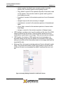
3
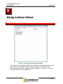
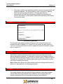
Using LeCam Client
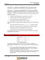
3.1 Description and Usage
Figure 3-1 LeCam Client's Camera Finder Window
The LeCam Client application allows you to find any Lumenera Network camera
that is on the same sub-net as the computer running it. It is based on the
ZeroConf protocol similar to Apple’s Bonjour application. Figure 3-1 shows the
Camera Finder tab of this application.
Page 22
Copyright © 2008
Lumenera Network Camera
User’s Manual
Release 1.8
3.1.1 Camera Finder Tab
This tab shows all cameras that are accessible and responding to ZeroConf
requests from the application. This list shows all the accessible cameras on your
network.
To select a camera, either double-click on the entry in the list, or enter in its IP
address or single-click the entry and hit the Connect button. The application will
connect to the desired network camera and automatically switch to the Main tab.
This tab also provides the ability to access a camera that has user or
administrator accounts enabled and configured. To access these types of
cameras, you need to enter in the account credentials by following these steps:
1. Select either the admin or user account from the drop-down menu.
2. Type in the password associated with this account in the edit box beside the
drop-down menu.
3. Select the camera you wish to connect to by either:
a. Double-clicking it in the list
b. Single-clicking it in the list and hitting the Connect button
c. Manually entering its IP address and hitting the Connect button
The provided credentials will be used on all subsequent calls to the camera.
Note: It is not necessary to enable the admin or user account on the camera. By
default, the camera does not have these accounts enabled. If your camera does
not have either of these accounts enabled, leave the password field empty.
Copyright © 2008
Page 23
Lumenera Network Camera
User’s Manual
Release 1.8
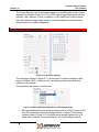
3.1.2 Main Tab
The Main tab, shown in Figure 3-2 allows you to see a preview from the camera,
scroll around the camera’s image window with either the mouse or the arrow
buttons, zoom in and out of the preview and adjust the brightness and white
balance. It also allows you to capture individual images that can then be saved in
a file.
This tab provides the following controls and displays:
•
A thumbnail view of viewable area seen by the camera
•
A size adjustable preview window
•
Arrow buttons that allow you to pan around the camera’s field of view.
•
Drop-down zoom control menu
•
A button to save the current camera settings to non-volatile memory
•
Buttons to adjust the image brightness
•
A button to adjust the color balance of the image
•
A button to capture a single image from the camera and display it into
another window, where it can be saved to a file.
The thumbnail view has a red rectangle that shows the portion of the full camera
image that is displayed in the preview window. The position of this rectangle can
be changed with the mouse or by the arrow buttons. The size of this rectangle is
dictated by the size of the preview window and the current zoom level.
Page 24
Copyright © 2008
Lumenera Network Camera
User’s Manual
Release 1.8
Figure 3-2 LeCam Client Main Tab
The preview window size can be changed by changing the size of the LeCam
Client application’s dialog box size. You can move the mouse to the edges or the
corners of the dialog box and resize it. As the application’s dialog box changes in
size, the preview adjusts itself accordingly. You can also hit the maximize or
minimize buttons on the title bar to maximize the size of this dialog box or hide it
from view. You can also pan around the camera’s field of view by clicking and
holding down the left mouse button and “dragging” the image in the direction you
want to view.
The Save settings button saves all the current camera settings to non-volatile
memory, overwriting the default boot up settings. On the next reboot of the
camera, these saved settings will be restored.
The Brightness buttons change the camera’s luminance target value used for the
auto-exposure, auto-gain and auto-iris algorithms. This will cause the image
intensity to either increase or decrease to achieve the new target intensity.
Note: In low light conditions, the target intensity may not be reachable so
increasing the brightness may not have any effect on the image intensity.
The Color balance button adjusts the camera’s color gains to make the white
parts of the image purer.
The Capture button captures a single full view image from the camera and places
it inside another dialog box, as shown in Figure 3-3. In the Capture dialog box,
Copyright © 2008
Page 25
Lumenera Network Camera
User’s Manual
Release 1.8
Figure 3-3 LeCam Client Capture Dialog Box
you can resize the image by resizing the dialog box, zoom in or out of the image
through the Zoom menu or save the image to a file through the File menu.
3.1.3 Advanced Tab
The Advanced tab provides a thumbnail view of the current image and provides a
web link to access the camera’s web interface. It will open up the default web
browser and automatically connect to the camera. This interface allows you to
access additional features and properties of the camera that may not be
controlled directly by the LeCam Client application.
Page 26
Copyright © 2008
Lumenera Network Camera
User’s Manual
Release 1.8
4
Understanding Your Camera
4.1 Shutter Types
The images produced by your camera are affected by the speed of moving
objects in relation to the camera, the ambient light level, and other factors.
Understanding the shutter types used by the different cameras is important in
getting the best images possible from your camera.
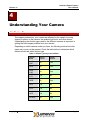
Depending on which camera model you have, the following electronic shutter
types may or may not be present. Check the table below to determine which
camera model has which shutter type.
Table 4-1 Shutter Types by Camera Model
Camera
Model
Rolling
Shutter
Global
Shutter
Le045
Li045
No
Yes
Le075
No
Yes
No
Yes
Yes
No
Le259
No
Yes
Le275
Yes
No
Le375
Yes
No
Le575
Yes
No
Le11059
No
Yes
Le165
Li165
Le175
Li175
Copyright © 2008
Page 27
Lumenera Network Camera
User’s Manual
Release 1.8
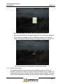
4.1.1 Rolling Shutter
With a rolling shutter the exposure process begins, whereby, rows of pixels in the
image sensor start exposing in sequence, starting at the top of the image and
proceeding row by row down to the bottom. At some later point in time, the
readout process begins, whereby, rows of pixels are read out in sequence,
starting at the top of the image and proceeding row by row down to the bottom in
exactly the same manner and at the same speed as the exposure process.
The time delay between a row starting to expose and a row being read out is the
integration time, also known as the exposure time. This integration time can be
varied from a single line (start exposure followed by a read out while the next line
is exposing) up to a full frame time (last line starts exposing at the bottom of the
image before reading starts at the top). In some cases, longer exposures can be
obtained by delaying the read out even longer (during which time, the entire array
is exposing).
Since the integration process moves through the image over some length of time,
skewing of moving objects may become apparent. For example, if a vehicle is
moving through the image during capture, light from the top of the vehicle will be
integrated at some earlier time than light from the bottom of the vehicle, causing
the bottom of the vehicle to appear slanted forward in the direction of motion. For
most slow moving objects or still image capture, this motion artifact is not
noticeable.
4.1.2 Global Shutter
With a global shutter, the entire image array starts exposing at the same time
(globally). At some later point in time, the entire image array stops exposing at
the same time and the image is read out in sequence, starting at the top of the
image and proceeding row by row down to the bottom (sometimes odd rows are
read out first followed by the even rows). The difference from the other modes is
that during readout, the imager is no longer integrating light.
The time delay between the start of exposure and end of exposure is defined as
the exposure time and it represents the total amount of time that the image
integrates.
Because all the pixels start exposure at the same time, integrate over the same
interval, and stop exposing at the same time, the potential for motion artifacts is
reduced compared with cameras with rolling shutters.
4.2 Subwindowing, Subsampling & Binning
Subwindowing, also known as region of interest (ROI), is the ability to select a
reduced image size within the whole imager array. The inherent resolution of the
image sensor is retained, but the frame rate can be increased due to the reduced
image size. The Le175 camera, for example, can output a subwindow of
640x480 pixels positioned nearly anywhere inside the original 1280x1024 field of
Page 28
Copyright © 2008
Lumenera Network Camera
User’s Manual
Release 1.8
view. The subwindow provides a smaller partial field of view. There are
limitations on the granularity of the subwindow size and position (8 pixels for
Network cameras).
Subsampling, also known as decimation, involves discarding every nth pixel or
pixel pair in the image. Subsampling involves a trade-off of lower image quality
(resolution) in favour of higher frame rate. For example, the Le175 camera with
maximum resolution of 1280x1024 pixels can discard every second pixel in both
the X and Y directions and output an image composed of 640x512 pixels that still
covers the entire available field of view. Not all Lumenera Network cameras
support subsampling. Those that do, support subsampling levels of 2, 4 or 8.
Subsampling is a feature of CMOS active pixel image sensors.
Binning is a feature of CCD image sensors that reduces resolution in a manner
similar to subsampling with the key distinction that the signal charge in
neighboring pixels is combined rather than discarded. The resulting resolution
would be the same as for subsampling, and the frame rate is also increased, but
no analog signal is lost in the process. One of the implications for binning on a
color image sensor, that uses mosaic pattern filters on the pixel array, is that the
color information is lost when binning the signal in adjacent pixels.
Both binning and subsampling use the API property subsampled, with the
values indicated in the table below.
Table 4-2 Subsampling and Binning Modes
Models
Supported modes
subsampled
value
Le/Li045
Feature not supported
0
Le075
Native resolution
0
Le165 / Li165*
Binned 2 X 2
1
Le259*
Binned 4 X 4
3
Le11059*
Binned 8 X 8
7
Le175 / Li175*
Native resolution
0
Le275
Decimate 2 X 2
1
Le375
Decimate 4 X 4
2
Le575*
Decimate 8 X 8
3
*Not all subsampled modes are available on these models in the current versions of the firmware.
4.3 Camera Mode: streaming video (MJPEG)
The Lumenera Network cameras operate only in continuous capture mode.
There is no capability for acquiring triggered snapshots. Image frames are
continually being captured, JPEG compressed, and stored in a rolling memory
buffer. When requested, the data is transmitted to each user over the Ethernet
Copyright © 2008
Page 29
Lumenera Network Camera
User’s Manual
Release 1.8
connection. Where multiple users access the camera simultaneously or
bandwidth is limited, some frames may be dropped.
There are two primary factors that affect the image quality of the cameras:
•
The camera’s auto-exposure algorithm can cause issues that may
decrease the quality of the images produced. When the camera’s gain
value is increased due to low light conditions, the noise present in the
images is also increased resulting in poorer image quality. Also, the
exposure value may be increased to help in low light conditions which
produces a longer acquisition time thus slowing down the camera’s frame
rate.
•
The camera uses a JPEG compression algorithm to compress the images
transferred over the network. The compression used in JPEG images is a
lossy compression, meaning that some image information is lost during
compression. Depending on the compression ratio used, you may see a
variation in the image quality. Higher compression ratios will increase the
loss of image information in the final JPEG image file.
The maximum network capacity required for the Network camera is 1.5MB/s
using HTTP for Le-series cameras. For the Li-series cameras and the Le045
model, the throughput is up to 5 MB/s if required. The MJPEG streaming video
from the camera maintains a constant bandwidth without burst traffic. The frame
rate performance diminishes with network congestion.
4.4 Scanning Mode
Most Lumenera Network cameras operate in progressive scan mode. In a
progressive scan camera, the entire image is integrated (exposed) at one point in
time (for global shutters) or line-by-line from top to bottom (for rolling shutters).
4.5 Auto-Brightness Control (ABC)
The camera will adjust the iris, exposure and gain so as to ensure that the image
brightness is maintained. The way in which the camera adjusts these settings is
based on a predefined algorithm. Below is a simplified description of how the
camera adjusts these settings based on the changing lighting conditions.
Ambient light is getting darker:
1. The camera will first try to adjust the DC iris to allow more light to enter into
the camera and be seen by the camera's sensor.
2. When the DC iris is open completely, the camera will start to increase the
exposure value to the first knee point.
Page 30
Copyright © 2008
Lumenera Network Camera
User’s Manual
Release 1.8
3. When the exposure knee point is reached, the camera will adjust the global
gain to its first knee point.
4. The camera will further increase the exposure and then the gain until the
maximum exposure and gain values are reached.
Ambient light is getting brighter:
1. The camera will decrease the global gain value until it reaches the first knee
point.
2. The camera will decrease the exposure until it reaches the first knee point.
3. The camera will further decrease the gain and then the exposure until both
these parameters are at their minimum values.
4. Once the exposure and gain values are at their minimum values, the camera
closes the DC iris to minimize the amount of light seen by the sensor until the
iris is closed.
The Lumenera website provides an Application Note that describes further how
the Auto Brightness Control (ABC) works on Lumenera Network cameras.
4.6 Locking Connector for External Power and I/O
The 10-terminal locking connector plugs into a socket on the rear of the camera
(item 2 in Figure 2-1, Figure 2-2, or Figure 2-3). The connector is keyed to fit in
only one orientation. For large-format cameras, the top-to-bottom orientation of
the connector is rotated by 180-degrees in the usual upright camera mounting
position.
Table 4-3 Detailed Pin-Out of Locking Power, I/O & Rs232 Connector
Le series Cameras
Figure 4-1 Diagram of the
10-Pin Locking Power
Connector
Copyright © 2008
1
DC Iris
Drive +
(Yellow)
DC Iris
Drive (Orange)
2
3
DC Iris
Control +
(Red)
DC Iris
Control (Brown)
4
5
Trigger
In +
7
Alarm
Out +
9
Power +
Trigger
In –
Alarm
Out –
Power -
6
8
10
7
Alarm
Out +
Alarm
Out –
8
9
Li series and Le045 Cameras
1
3
5
Trigger
RS232 RX Not used
In +
Trigger
RS232 TX Not used
In –
2
4
6
Power +
Power 10
Page 31
Lumenera Network Camera
User’s Manual
Release 1.8
To open the lock and insert a wire, use a small flat-head screwdriver to push the
metal lock in. Remove the screwdriver from the lock to secure the wire. The wire
gauge must be AWG 18 to AWG 28.
The locking connector provides terminals 9 (Power +) and 10 (Power-) to supply
power to the camera where PoE is not used. Be sure to observe the power
requirements listed for each model referring to Table 2-2, Table 2-3, and Table
2-4 in Section 2.1. The recommended universal power supplies are:
Lu8401 (+24 VDC) for all small-format cameras.
Lu8501 (+12 VDC) for the Le259 and Le11059.
Note: Do not ground-reference either terminal of the AC power supply as you
may permanently damage the camera.
For Le-series cameras without an integrated dc-iris socket, use Lumenera’s
Le902 dc-iris adapter. See Section 5.4 for details.
Please refer to Section 5.7 for details of interfacing to the general purpose input
and output (GPIO) terminals.
4.7 RJ-45 Ethernet Jack
The Ethernet cable connection on the Network camera uses a standard RJ45
connector and is shown in Figure 4-2. The pinout of this connector is standard for
10BASE-T and 100BASE-TX configurations.
For cameras that use Power over Ethernet (PoE), the differential signalling pairs
also carry DC power. The use of conductors 1, 2, 3, and 6 (no “spare” pairs)
corresponds to power mode A of IEEE 802.3af PoE standards.
1 2 3 4 5 6 7 8
1 2 3 4 5 6 7 8
Position 1
Position 2
Position 3
Position 4
Position 5
Position 6
Position 7
Position 8
Tx +
Tx –
Rx +
Not used
Not used
RxNot used
Not used
Figure 4-2 RJ45 Connector Pin out
Page 32
Copyright © 2008
Lumenera Network Camera
User’s Manual
Release 1.8
4.8 Lens Mount
4.8.1 Small Format and Intelligent Cameras
These Network cameras are equipped with an industry standard CS-Mount lens
mount with adjustable back focus. A 5mm spacer (Lumenera part Lu901) can be
added to the lens mount to accommodate C-Mount lenses.
4.8.2 Large Format Cameras
Large format cameras are equipped to support off-the-shelf 35-mm SLR lenses.
The standard format supported is the Canon EF mount. Contact
[email protected] to inquire about support for other 35-mm lens
formats.
4.9 Analog Video Output
Figure 4-3 Web Browser Option to Enable/Disable the Analog Output
For Li-series cameras, the BNC connector on the camera back panel (item 3 in
Figure 2-3) provides a composite video output in NTSC format (PAL/SECAM
formats are in development). The analog video output is especially useful for
CCTV installers during the initial setup of the camera and lens when using a CRT
monitor to verify the camera alignment and focus are correct.
Note: After installation, in order to maximize the efficiency of the IP camera, the
system administrator can disable the analog output.
Copyright © 2008
Page 33
Lumenera Network Camera
User’s Manual
Release 1.8
The analog video output can be disabled by clearing the Analog video output
on/off checkbox found in the web browser user interface under the Streaming
web link of the Admin Mode tab (see Section 6.8 for more details). The API
property to set to disable the analog output is:
frame_buffer_enable=0
4.10
Audio Functions
For the Li-series cameras and the Le045, a single audio input/output jack is
located on the back panel (see item 5 in Figure 2-3). The audio input/output jack
will accept a 3.5mm stereo plug. The connection is non-standard in the sense
that one mono audio input and one mono audio output share a single stereo
plug.
Table 4-4 Mic In Audio Specifications
Specification
Absolute max. input
Recommended max. input
Input resistance
Bias voltage
Bias current source
Value
3.6 V
0.707 VRMS
80 kOhm
2.5V typ. (programmable)
4 mA @ 2.5V
Table 4-5 Line Out Audio Specifications
Specification
Recommended load
Full-scale output voltage
Value
10 kOhm
2.0 VPP
0.707 VRMS
@ 0-dB gain (programmable)
Table 4-6 Configuration of 3.5 mm Stereo Plug
Conductor
Connector format
Tip
Ring
Sleeve
4.11
Function
3.5 mm stereo plug
MIC IN
LINE OUT
GROUND
Factory Reset
Several methods are available to revert to saved/default settings on the Network
camera. This includes both a reset switch and software commands.
Note: By restoring the factory default settings, the camera’s network settings are
set to contact a DHCP server to acquire a dynamic IP address. The camera IP
address may change after the reset is complete. If no DHCP server is present,
Page 34
Copyright © 2008
Lumenera Network Camera
User’s Manual
Release 1.8
the camera may be found using the fallback IP address (192.168.1.222) or the
link-local IP (described in more detail in Section 2.3.6).
4.11.1 Factory Reset Switch
On Le-series cameras (excluding the Le045) there is a recessed reset switch on
the camera near the RJ45 port that can be used to perform a hardware reset to
factory defaults. The reset sequence using the reset switch is as follows:
1. Turn off the camera by disconnecting the power cable.
2. Locate the small hole next to the serial port on the back of the camera.
3. Insert a pin or paperclip into the hole to depress the Factory Reset button.
The button clicks when it is pressed down.
4. While holding down the Factory Reset button, restore power to the camera by
connecting the power cable. Continue holding down the Factory Reset button
until the orange boot LED on the Ethernet connector blinks rapidly
(approximately 30 seconds).
4.11.2 Software Reset & Recovery Commands
4.11.2.1
Reset defaults using the Web User Interface.
For the commands below, substitute your actual camera IP address for
192.168.1.222.
To set default settings for image parameters only, click on the Image Settings link
in Admin Mode.
To revert to your power-on settings without power cycling, click on the Load
Settings link in Admin Mode or enter:
http://192.168.1.222/cgi-bin/load_settings
To reboot the camera, click on Reboot Camera in Admin Mode, or enter:
http://192.168.1.222/cgi-bin/reset
To revert to factory settings, enter:
http://192.168.1.222/cgi-bin/
load_settings?filename=factory_defaults
To reboot and revert to factory settings (same as hardware reset to factory
defaults using button on rear of the camera), enter:
http://192.168.1.222/cgi-bin/nph-reset-factorydefaults.sh
4.11.2.2
Reset defaults using a Telnet or Serial Port Connection
Refer to Sections 5.7 and 5.8 for information on telnet and serial consoles. The
syntax for entering console commands is the same when using either a telnet
interface or the camera’s RS-232 serial interface.
Copyright © 2008
Page 35
Lumenera Network Camera
User’s Manual
Release 1.8
To revert to your power-on settings without power cycling, enter:
l load_settings
To load defaults for image settings only, enter:
l put_settings_from_property default_image_params
To reboot the camera, enter the following:
l reset
To revert to factory settings (same as hardware reset switch) enter:
l nph-reset-factory-defaults.sh
Page 36
Copyright © 2008
Lumenera Network Camera
User’s Manual
Release 1.8
5
Configuring and Using Your
Network Camera
5.1 Video Management Support
Lumenera has partnered with several third-party Video Management providers
and companies. Our partners include Network Video Recorder (NVR) application
software providers and manufacturers of Digital Video Recorder (DVR) hardware.
Both types of video management systems include software that allows a system
administrator to configure multiple networked cameras and provide functions for
video previewing, recording and playback, and also provide archive
management. These applications also allow configurable recording schedules
either based on a timed event or on an alarm/motion event.
The Lumenera website includes an up-to-date list of our Video Management
Partners:
http://www.lumenera.com/security
Please refer to each partner website for more information on their respective
applications or to download evaluation/demo versions of their software.
5.2 Mounting the Camera
The camera provides a standard ¼”-20 tripod mount. This mount can be used
with any tripod or other mount that uses this screw type.
For small-format cameras, the mount can be moved from the bottom to the top of
the case by loosening the 4 nylon screws using a small screwdriver. Use caution
to avoid damaging or breaking the nylon screws.
Contact [email protected] for our latest accessories list, including
weatherproof enclosures and mounting brackets.
For lab or bench top use, use mounting hardware from opto-mechanical
suppliers such as Thorlabs, Newport, Melles Griot and others.
Copyright © 2008
Page 37
Lumenera Network Camera
User’s Manual
Release 1.8
5.3 Lens Selection
The Network camera provides a CS-mount lens mount as a standard feature in
small format models. A C-to-CS mount adapter, Lumenera part number Lu901,
can be added to the mount to accommodate a C-mount lens. Be sure to select
the optical format (size) appropriate to your camera. Select a lens with an optical
format equal to or larger than that of the camera’s sensor.
Large-format models use Canon EF-mount 35-mm SLR lenses.
Table 5-1 Optical Format for Each Camera Model
Camera
Le045 / Li045
Le075
Le165 / Li165
Le175 / Li175
Le259
Le275
Le375
Le575
Le11059
Optical format
1/3 inch
1/3 inch
2/3 inch
1/2 inch
35 mm
1/2 inch
1/2 inch
1/2.5 inch
(uses 1/2” lens)
35 mm
It is important to select megapixel lenses for use with megapixel cameras. Many
conventional, low-cost, low-performance lenses designed for low-resolution
CCTV cameras are not suitable as they cannot resolve images properly on
sensors with small pixel pitch as those used in megapixel lenses. These lenses
may cause aberrations or other imaging artifacts in the video feed that may be
undesirable.
There are a few lens features to consider when purchasing lenses for your
camera:
•
Be sure to look for lenses that specifically state that they are megapixel
lenses.
•
Vari-focal lenses can be more difficult to adjust for megapixel cameras
than with low-resolution cameras. Since in most camera installations, the
field of view will be constant, you may want to consider a fixed focus lens.
Lumenera provides a limited selection of lenses that are suitable for your
camera. Feel free to contact us at [email protected] or
[email protected] for more information on selecting a lens that is
suitable for your application.
Page 38
Copyright © 2008
Release 1.8
Lumenera Network Camera
User’s Manual
5.4 Using DC auto-iris lenses
The Lumenera Network cameras support connecting and controlling 4-wire DC
auto-iris lenses. Auto-iris lenses have the capability to vary the lens aperture. In
low-light situations, the iris opens to improve the light gathering ability of the
camera. In bright conditions such as direct sunlight, the iris closes, reducing glare
and increasing the depth of focus. This section explains how you can connect
and configure the camera to use DC auto-iris lenses.
Note: Lumenera Network cameras only support galvanometric type DC-iris
lenses. Video auto-iris lenses that control the iris based on the composite video
output of an analog video camera are not supported.
5.4.1 Connecting the DC-Iris Lens
Most Li-series cameras come with an integrated, industry-standard 4-conductor
dc-iris socket.
For the Le-series cameras, use the Le902 DC-iris adapter to connect a DC-iris
lens. The Le902 DC-iris adapter provides a miniature socket for 4-wire dc-iris
lenses wired onto the 10-position plug on the Network cameras. This part can be
purchased directly from Lumenera or through your local Sales representative.
Manually stripping and connecting the wires within the DC-iris lens control cable
is not recommended due to the fine gauge wires used. However, one can
manually wire the DC-iris lens directly into the 10-position socket of the Le series
Network cameras. Table 4-3 in Section 4.6 provides a detailed description of the
10-position socket.
5.4.2 Configuring Camera to Use DC-Iris Lens
To configure the camera to use the features of the DC-iris lens:
1. Open a web browser and load the camera’s main web page.
2. On the main webpage, select Admin Mode tab.
3. Select the Exposure/Gain link
4. Select the AutoIris check box.
5. (Optional) Specify the minimum exposure.
6. Select the Save Settings link to store your settings changes to the non-volatile
memory.
The camera normally combines automatic gain and exposure control with DC-iris
control to maintain the desired target brightness of the image. The minimum
exposure defines the exposure time at which the camera switches over to DC-iris
control from auto-exposure control (default: 6 ms). Enter a value of zero for the
minimum exposure to defer DC-iris operation until the camera applies the
shortest possible electronic exposure control time.
Copyright © 2008
Page 39
Lumenera Network Camera
User’s Manual
Release 1.8
You can also configure the DC-iris using the following API parameters.
autoiris=1
minimum_exposure=<your minimum exposure value>
5.5 Input/Output and Synchronization with External Events
The camera is equipped with general purpose input/output (GPIO) terminals on
the 10-position socket on the rear of the camera. The GPIO terminals connect to
opto-isolators to help prevent accidental damage to the camera hardware.
5.5.1 General-Purpose Input
A hardware GPIO input is available that allows triggering alarm behaviors such
as FTP transfer of images (alarm_enable_ftp API property). The
synchronization is limited to approximately one frame period. To enable the
hardware input, go to the Alarms link on the Admin Mode tab, and select the “IO
IN Alarm Enable” option, or use the io_in_alarm_enable API property. In
addition to FTP image transfer, other alarm responses include sending an email
notification and or a UDP alarm message packet.
The camera has an alarm_delay property to limit the number of alarms
received in a short time interval by specifying the delay in seconds to wait
between alarm events. The factory default for the delay between alarms is 60
seconds (1 minute). You can reduce the delay in the Alarms page on the Admin
Mode tab by entering a value greater than zero in the Delay Between Alarms
field. The alarms page also has options to select edge triggering (looks a the
transition point where the digital signal changes from one voltage to the other,
e.g. going from a digital 0 voltage to a digital 1 voltage) between instead of level
triggering (looks at the voltage level of the signal), and to trigger on a negative
level (when the voltage is 0V DC) or falling edge (when the signal is transitioning
from a digital 1 voltage to a digital 0 voltage). Refer to Section 6.7 for details.
Input +
Input –
Figure 5-1 Input (GPI) Circuit
The GPI opto-isolator circuit consists of a photo-transistor and a 200 Ω resistor.
A minimum current through the circuit is required to generate an alarm event.
Page 40
Copyright © 2008
Lumenera Network Camera
User’s Manual
Release 1.8
The circuit is designed to work with a 5 V input without any other external
components. For higher voltages an external resistor or other limiting device
must be used to limit the current.
Table 5-2 Input (GPI) Opto-Isolator Parameters
Specification
Minimum current
Maximum current
Diode forward voltage drop (typical)
Reverse current, maximum, at Vr = 4V
Reverse voltage, maximum allowed
Maximum voltage on either pin
Value
10
mA
30
mA
1.2 V
10
µA
5
V
30
V
5.5.2 General-purpose output
A hardware GPIO output is also available. This has several modes that can be
specified by selecting the Alarms link on the Admin Mode tab and selecting the
Output Select options listed under the heading DC Output. Each mode defines a
setting of the output_select API property as shown in the table below.
Table 5-3 General Purpose Output Modes Set Using output_select
Value of
output_select
off
on
alarm
GPO behavior
Comments
Off (disabled)
On (enabled)
Pulse upon alarm
For all models.
For all models.
Responds to either general-purpose input or
motion detection alarm
Use with Le075. Le/Li165, Le259, or Le11059
global-shutter cameras to expose the image
using a flash.
Similar to “strobe” for rolling-shutter models.
Line 1 is not exposed by the flash.
strobe
Pulse when exposure is valid
for each frame
start_of_readout
Pulse when line 1 of the
image begins readout.
To test the functioning of the general purpose output, use the strobe API
function to send a single pulse with duration in milliseconds set by the API
property strobe_length (default is strobe_length=10 ms).
Using a web brower:
http://192.168.1.222/cgi-bin/strobe
Using a telnet or serial console:
l strobe
The output opto-isolator terminals connect to the collector and emitter of a phototransistor. When the output is active, the transistor will conduct current from the
collector to the emitter.
The output can be used to control external sensors and light sources. The sensor
may be a logic gate or the base of a higher power transistor for an external
device that is to be activated due to a motion alarm or input alarm, with the
camera setting of output_select=alarm. When working with external light
Copyright © 2008
Page 41
Lumenera Network Camera
User’s Manual
Release 1.8
Output +(collector)
Output –(emitter)
Figure 5-2 Output (GPO) Circuit
sources, the output can be connected to the trigger input of a strobe lamp or LED
illuminator to synchronize the flash with the camera exposure time, using the
output_select setting strobe or start_of_readout.
An external bias voltage across the output terminals is needed to generate a
proper signal. Typically, the collector is tied to a voltage source and the emitter is
grounded. One pin should be connected to a pull-up or pull-down resistor to limit
the current.
Table 5-4 Output (GPO) Opto-Isolator Parameters
Specification
Collector current, maximum
Collector-emitter voltage, maximum
Emitter-collector voltage, maximum
Value
40
mA
50
V
5
V
5.6 Use of Flash or Strobe
A flash or strobe may be used with any camera model and the option is available
to provide a programmable trigger signal from the camera to the flash or strobe
device to tell it when to fire. However, the type of shutter mode being used will
dictate what conditions will be required and how well flash photography will work
with the camera.
5.6.1 Flash with Global Shutter
The use of a flash or strobe with a global shutter has no limitations or concerns.
The strobe signal from the camera is generated at a user selectable delay from
the start of the exposure. Very short, global exposures can be used, so, there will
be no blurring, skewing or overexposure due to long exposures. Also, the lens’
iris can be used to help limit the amount of light that reaches the sensor which
can be helpful to increase the depth of focus of the captured images.
5.6.2 Flash with Rolling Shutter
The use of a flash with rolling shutter is only feasible for cameras that allow
exposures longer than frame readout time (typically ~30 ms). This is because
with exposures less than that, only a band across the imager is being exposed at
Page 42
Copyright © 2008
Lumenera Network Camera
User’s Manual
Release 1.8
a given point in time when the flash fires. As a result, it will only illuminate that
region of the imager. Longer exposures are required when using rolling shutter
imagers since the flash must be fired at a time when all the pixels of the imager
are simultaneously exposed to light.
The flash trigger to be used with rolling shutter cameras is through the setting of
the output_select=start_of_readout mode. The start_of_readout
signal from the camera is generated at the end of exposure of line 1, the top line
of the image. As a result, the first line of the image will never be exposed by the
flash. The exposure and readout of each row of the rolling shutter image sensor
proceed sequentially, one row at a time. As a result, the bottom rows of the
image will only be exposed by the flash if the exposure time exceeds the frame
readout time.
Generally, the ambient lighting should be low enough (i.e. dark) so that during
the overall exposure the ambient light and/or the lens iris should be almost
completely closed so that the ambient light will not contribute much to the overall
brightness of the image. This is particularly true if the flash is being used to stop
the motion of a fast-moving object, otherwise, blurring or skewing may occur in
the captured image. For imaging still objects, this is not as much of a concern. In
this case, you only need to ensure that you are not overexposing the object with
both a long exposure and a powerful flash. When using a flash, the duration of
the flash pulse defines the exposure of the image even though the camera’s
exposure time is set longer.
5.7 Serial Port Configurations
The serial port can be configured as a console or to control various accessories.
This section explains how to configure the serial port for both options.
5.7.1 Using the Serial Port as a Console
The factory default is to set the camera’s serial port to console mode. To open a
serial console session with the camera, use a terminal emulator application such
as HyperTerminal or Token2. The default settings of the camera’s serial interface
are as follows:
serial_use=console (required for console access)
serial_speed=19200 (the baud rate)
serial_flow=none (the flow control method)
Specify the COM port in use on your PC, the baud rate, number of data bits (8),
parity (none), and stop bits (1).
For example, in Token2 (http://www.choung.net/Token2Plus/) to connect using
the COM2 port of your Windows PC, specify the resource as:
com://2,19200,8,n,1
Copyright © 2008
Page 43
Lumenera Network Camera
User’s Manual
Release 1.8
When the console session is established, the camera will respond with a prompt
of #. At this point, it is possible to enter API commands and queries using the
command line interface. For example, the following command returns the current
firmware version information:
l version
The console can also be used to get and set camera properties:
l get exposure
l set autogain=1
5.7.2 Enabling the Serial Port for Controlling Accessories
Lumenera Network cameras can provide access to the external serial port by
other Internet hosts to control accessories connected to it. This feature is known
by the short name of sersock (SERial SOCKet), sometimes also called a
“transparency” or “pass-through” mode.
To enable the sersock mode, set the following camera parameter, save settings,
and reboot the camera.
serial_use=accessory
When the camera is booted with this option, it will relay all bytes received on port
8548 of a TCP connection to the serial port with minimal buffering and delay, and
forward all bytes received back through the same connection. If no TCP
connection exists, all received bytes are ignored.
The baud rate and parity of the serial port are set by the serial_flow,
serial_speed and serial_echo parameters. The factory defaults for these
parameters are:
serial_flow=none
serial_speed=19200
serial_echo=1
Note: Currently hardware flow control is not implemented on the serial port and
software flow control is not used by default. Using the serial port for accessory
connections prohibits using it for a control console. If the camera is reset to its
factory defaults, the serial port will revert back to console. If the accessory sends
data to the camera while the camera is set to console mode then normal
operation of the camera may be disrupted.
5.7.2.1 To Enable Sersock mode from a Telnet Console
A telnet console can be used to enable the camera’s serial port. The following
provides an example of how to setup the serial port to run at 9600 baud. Type
each line below into a telnet console connected to the camera:
l set serial_use=accessory
l set serial_speed=9600
Page 44
Copyright © 2008
Lumenera Network Camera
User’s Manual
Release 1.8
l save_settings
l reset
5.7.2.2 To Enable Sersock mode from a Web Browser
The serial port can also be enabled with a web browser. The following provides
an example of how to setup the serial port to run at 9600 baud. Type each line
below individually into your web browser’s web link address field:
http://192.168.1.222/cgi-bin/set?serial_use=accessory
http://192.168.1.222/cgi-bin/set?serial_speed=9600
http://192.168.1.222/cgi-bin/save_settings
http://192.168.1.222/cgi-bin/reset
5.7.3 Controlling Accessories through the Serial Port
Access to the serial port can be done through any TCP connection made to the
sersock port of the camera. One way of accessing this port is through a telnet
console (e.g. telnet 192.168.2.2 8548).
The first connection to the sersock port maintains control of it until the connection
is closed. This means that though other connections to the port may appear to
succeed they will not be able to transmit bytes through the serial port. Only the
main connection will have access to transmit bytes through this port. All
connections will receive all bytes received by the serial port.
Below are some key points to note when accessing the sersock port:
•
If you are using a telnet session to access the camera, bytes will not be
sent to the camera until a full line has been entered. A full line is typically
indicated by a carriage return or enter key.
•
Internet firewalls can restrict access to the sersock port. To ensure proper
operation, be sure that TCP packets can be routed from the necessary
control hosts to port 8548 on the camera.
•
It is also important that this port be protected from general unauthorized
access (e.g. the Internet at large).
5.8 Using Telnet to connect to the camera
5.8.1 Starting a Telnet session
To initiate a Telnet session on the camera from a Windows PC, select the Start
Menu, then Run… and enter “cmd” to open a Command Prompt (MS-DOS)
window. At the C:\ prompt, enter the following, replacing 192.168.1.222 with
your camera IP address.
telnet 192.168.1.222
Copyright © 2008
Page 45
Lumenera Network Camera
User’s Manual
Release 1.8
You may specify the ZeroConf camera name of the camera instead of the IP
address. For example, for the LE175 camera MAC ending in 0D:12:CD, the
default Bonjour name is le175c-0d12cd.local.
The camera will respond with a prompt of #. At this point, it is possible to enter
API commands and queries using the command line interface. For example, the
following command returns the current firmware version information:
l version
The console can also be used to get and set camera properties:
l get exposure
l set autogain=1
5.8.2 Enabling and Disabling Telnet
To disable the Telnet feature, select the Passwords link on the Admin Mode tab
of the web browser user interface, uncheck the Enable Telnet Daemon option.
The change will be applied immediately. To maintain your change to the camera
settings, select the Save Settings link.
The API property associated with the Telnet Daemon is the Boolean property
telnetd. Telnet is enabled when telnetd is true. The HTTP commands to
disable Telnet are as follows:
http://192.168.1.222/cgi-bin/set?telnetd=0
http://192.168.1.222/cgi-bin/save_settings
Avoid using a Telnet session to set telnetd=0, since the Telnet session will
immediately terminate, leaving no opportunity to save settings.
Page 46
Copyright © 2008
Lumenera Network Camera
User’s Manual
Release 1.8
6
Web Interface User’s Guide
6.1 Overview
This section describes the Network camera’s web interface and associated web
pages.
6.2 Main Web Interface
Figure 6-1 Main Web Page of Network Camera User Interface
The main web page, shown in Figure 6-1, provides images from the camera. By
default, the camera web pages open in View Mode. View Mode provides full-size
display of images from the camera. Click on the fit to window icon at the top
left of the image to display the image in full screen mode without other controls.
Click on the actual size icon in the top left of the screen to return to View
Mode.
The image refresh rate is selectable through the drop down menu. By default the
camera starts in auto-refresh mode, meaning that the web page will update as
fast as the network will allow.
Copyright © 2008
Page 47
Lumenera Network Camera
User’s Manual
Release 1.8
Figure 6-2 Buttons on Main Web Page
The View Mode web page also displays the camera model, part of its MAC
address and the date and time currently set in the camera. Three buttons allow
you to capture individual images, configure the camera settings or return to the
main web page view as shown in Figure 6-2. The buttons are described in detail
in subsequent sections.
6.2.1 Admin Mode Button
Figure 6-3 Links to Menus on the Admin Mode Tab
This button opens the Admin Mode web page as shown in Figure 6-3. Admin
Mode allows you to configure and control the camera settings. A reduced size
live camera image is provided at the right of the screen. By clicking on the links
on the left of the screen, you can access more web pages to perform the
following camera set-up tasks:
Page 48
•
Set exposure and gain settings (see Section 6.3)
•
Set the image settings (see Section 6.4)
Copyright © 2008
Lumenera Network Camera
User’s Manual
Release 1.8
•
Set geometry settings (see Section 6.5)
•
Configure the day/night mode of the camera (see Section 6.6)
•
Configure alarms (see Section 6.7)
•
Control the video streaming (see Section 6.8)
•
Setup the camera’s network settings (see Section 6.9)
•
Set the current date and time (see Section 6.10)
•
Assign passwords to lock the camera (see Section 6.11)
•
Provide watchdog information and control (see Section 6.12)
•
Update the camera’s firmware (see Section 6.13)
•
Reboot the camera (see Section 6.14)
•
Load image defaults (see Section 6.15)
•
Save current camera settings to and load settings from a configuration file
(see Sections 6.16 and 6.17)
•
Access documentation including the API functions and properties (see
Section 6.18)
Note: Not all links or settings listed above are available for all camera models.
Please refer to your camera’s Admin Mode web page for a list of supported
features and settings.
All the listed features and settings are described in more detail in the following
sections.
6.2.2 View Mode Button
Select this button to return to the camera’s main web page from the Admin Mode
web pages.
6.2.3 Single Image Button
Select this button to capture a single video frame from the camera’s video
stream. It displays this captured frame in a separate web browser window. The
image can be saved to a file by right-clicking the image and selecting the Save
Picture As menu option. This button calls the nph-image API function.
Copyright © 2008
Page 49
Lumenera Network Camera
User’s Manual
Release 1.8
6.3 Exposure and Gain Control
Figure 6-4 Exposure and Gain Controls
This web page allows you to control the camera’s exposure, gain and color gain
settings as shown in Figure 6-4. It also provides control of the auto-brightness
control (ABC) algorithms such as the auto-exposure, auto-gain and auto-iris
controls. You can set the target brightness for these algorithms and set the type
of algorithm to use. There are four types of algorithms for calculating the
brightness (luminance) of the images:
Page 50
•
Average: this algorithm calculates the average luminance in every image
from the camera and determines if the brightness should increase or
decrease based on the requested target brightness.
•
Median: this algorithm uses the median luminance of the image to
determine if the image brightness should change to be in line with the
requested target brightness.
•
Peak Detect: this algorithm looks at the bright areas (peaks) in the image
to determine how to adjust the brightness of the image to coincide with the
requested target brightness.
•
Dark Detect: this algorithm is similar to the Peak Detect algorithm but
instead looks at the dark areas to determine if any adjustments are
required to the overall image brightness based on the requested target
brightness.
Copyright © 2008
Release 1.8
Lumenera Network Camera
User’s Manual
Figure 6-5 Le045 and Li045 Exposure/Gain Controls
The Le045 and Li045 cameras use high-performance wide dynamic range image
sensors with unique properties for auto iris and white balance that are not
present in other camera models as shown in Figure 6-5.
If the AutoIris option is enabled on the Le/Li045, the camera will adjust the
aperture of a DC auto-iris lens to achieve the desired luminance when the
system gain drops below the AutoIris Threshold. Lower thresholds require
brighter scenes to engage the iris. If the threshold value is set too high then the
iris will close too readily and the image will become grainy (noisy).
The white balance functions of the Le/Li045 can be controlled using a numerical
“bias” value that corresponds to the light source color temperature. Larger
positive values generate images with more saturated red tones in the image.
Figure 6-6 Lens Control Options for 35mm Lenses In Exposure/Gain Controls
For the large-format cameras, the Exposure/Gain menu also provides for remote
control of the lens aperture and focus settings, shown in Figure 6-6. To control
the aperture, disable the AutoIris option and use the - and + buttons to change
Copyright © 2008
Page 51
Lumenera Network Camera
User’s Manual
Release 1.8
the f-stop of the lens. A smaller f-number corresponds to opening the iris and
admitting more light. To control the focus, use the arrow keys. The numerical
focus parameter will also vary when the arrow keys are used.
Figure 6-7 White Balance Section of Exposure/Gain Controls
This web page also includes properties to set the current color gains and to
enable the continuous white balance, as shown in Figure 6-7. The white balance
algorithm in use assumes a gray world algorithm meaning that it assumes that,
on average, the image will be gray or that all the colors will be equal. There are
four preset color balance ranges that help keep the continuous white balance
within more normal operating ranges: Default, Wide, Fluorescent, and Daylight.
Figure 6-8 Auto Window Section of Exposure/Gain Controls
You can also define a region of interest (ROI) in which the auto features are
applied, as shown in Figure 6-8. If the Auto Window check box is checked, you
can change the area the camera uses to calculate the luminance for the autobrightness control (ABC). By default, the camera uses the entire image size. To
define the dimensions of the Auto Window, click the left mouse button and drag
the mouse pointer in the preview image. You may also enter the Auto Window
height, width, and offset by entering numerical values in the fields provided.
Page 52
Copyright © 2008
Lumenera Network Camera
User’s Manual
Release 1.8
6.4 Image Settings Control
Figure 6-9 Image Settings Controls
The Network camera’s Image Settings control web page, shown in Figure 6-9,
allows control of the specific image properties listed below.
•
Gamma: allows changes to brightness in the mid-tone range without
affecting the maximum or minimum values.
•
Contrast: provides a means to increase or decrease the contrast in
images produced by the camera.
•
Saturation (for both daytime and night time conditions available with
day/night type cameras): adjusts the intensity of the color in images
produced by the camera. Values in the range from 0 to 50 are useful for
color images. For monochrome (black and white) images, such as in the
night mode of camera with the Day-Night filter mechanism, the saturation
is -100.
•
Brightness: allows changes to the overall brightness of the images.
•
Sharpness: allows the selection of different built-in edge enhancement
algorithms. Four options are provided:
o Default: the default value that provides normal edge enhancement
o Alternate: provides a less aggressive edge enhancement
o High: provides a high edge enhancement
o Off: turns off edge enhancement
•
Lighting source: provides a correction algorithm to improve the image
quality based on the light source in use. A color correction matrix applies a
color correction to the image to compensate for frequency response of the
lighting source. There are eight options available:
o unity: does not alter the color values in the images.
Copyright © 2008
Page 53
Lumenera Network Camera
User’s Manual
Release 1.8
o default: applies the default color correction matrix to provide
generic color correction good for most lighting sources.
o chip_default: corrects for the spectral response of the sensor used
on the camera. This correction matrix is generic and is good for
most lighting sources.
o fluorescent: corrects for the emission spectrum of most fluorescent
lights.
o daylight: improves the color accuracy in daylight.
o incandescent: corrects for the emission spectrum of incandescent
lights.
o xenon_flash: corrects for the emission spectrum of xenon strobe
flash lamps.
o halogen: corrects for the emission spectrum of halogen lamps.
•
JPEG settings: provides control over the quality and file size of the JPEG
images produced by the camera. These properties dictate how much
compression is performed on the image. There are two options available.
•
JPEG quality: the minimum JPEG quality can be set manually or an
automatic setting can be used. By default, the automatic JPEG quality
setting is set which will limit the quality based on the image detail and the
requested file size.
•
Maximum Size: this property sets the maximum file size allowed for each
image. The camera will sacrifice JPEG image quality to ensure that the
maximum file size is not exceeded. By default, maximum file size is not
set.
Figure 6-10 Image Settings Controls for Le045 and Li Series
Page 54
Copyright © 2008
Lumenera Network Camera
User’s Manual
Release 1.8
The Image Settings controls are implemented in a simplified way in the Li series
cameras, as shown in Figure 6-10. The JPEG quality is specified simply as Auto
(default), High, Medium, or Low. In addition, for the Le045 and Li045 cameras
with wide dynamic range image sensors, numerical sharpness and saturation
values are the only options supported.
6.5 Geometry Configuration
Figure 6-11 Geometry Settings
This web page, shown in Figure 6-11, allows you to configure image size and
region of interest (ROI), to flip and mirror and apply privacy maps and other
overlays to the images.
The properties that can be controlled are:
Figure 6-12 Binning/Subsampling Options In Geometry Settings
•
Binning/subsampling mode: these modes provide a full field of view (FOV)
from the camera but reduce the image file size in bytes. For all binning
modes shown in Figure 6-12, the pixels are summed together into one
super pixel, based on the mode selected. For a 2x2 binning mode for
Copyright © 2008
Page 55
Lumenera Network Camera
User’s Manual
Release 1.8
example, 4 pixels would be summed together to create 1 super pixel and
the image size would be reduced by a factor of 4. For all subsampling
modes, many pixels are omitted for every pixel that is retained.
Subsampling produces a similar reduction in the image file size as
binning, however, the image brightness is similar to that of the fullresolution image.
Figure 6-13 Geometry Grid
Page 56
•
Geometry grid: this grid pattern allows you to selectively choose a specific
ROI and position on the sensor using the mouse as shown in Figure 6-13.
Select the upper left corner of the ROI you wish and left-click and drag the
mouse pointer to define the rectangle that you wish to set for the image
ROI. When you release the left mouse button, the image dimensions will
be set accordingly. This action sets the ROI’s width, height, x and y offset
properties.
•
Width: this property displays or sets the image ROI width.
•
Height: this property displays or sets the image ROI height.
•
X Offset: this property displays or sets the image ROI X offset value.
•
Y Offset: this property displays or sets the image ROI Y offset value.
•
X mirror: this check box mirrors the image.
•
Y mirror: this check box flips the image.
•
Crosshair Enable: enables or disables a crosshair overlaid onto the
images returned from the camera. The crosshair can be used for aligning
the camera during setup.
•
Privacy Map Enable: enables or disables a privacy map overlay on the
images. This feature is explained in more detail in Section 6.5.1.
Copyright © 2008
Release 1.8
Lumenera Network Camera
User’s Manual
6.5.1 Privacy Map
The privacy map feature allows you to obscure certain areas in the field of view
of the camera. This feature is useful when the camera is deployed where certain
areas require privacy. For example, you may wish to mask a window on a
privately owned building.
The privacy map dimensions can be altered using the Grid Height and Grid Width
fields in the web interface. The mouse pointer can be used to enable particular
squares in the privacy map. A check mark is displayed in each square when
activated. Be sure to select the Save Settings link to store your changes in the
non-volatile memory.
To configure the privacy map programmatically, you should understand how the
privacy map is implemented in detail. The privacy map is an array or grid of
privacy zones within the image. Each zone may be enabled (private) or disabled
(visible). The privacy map width and height are, respectively, the number of
columns and rows in the privacy map grid.
The privacy_map parameter defines the specific elements of the privacy map
grid that will be marked private. The privacy_map is a binary value that is
stored as a hexadecimal value. The number of bits in the privacy map is simply
the product of privacy map width and privacy map height. The most significant bit
of the privacy map value corresponds to the upper left privacy map grid element.
The following bits correspond to the next grid element to the right until the end of
the row. The following bits continue on the next row to the last bit which defines
the bottom right grid element.
Note: The privacy map is defined based on the sensor coordinates and ignores
Figure 6-14 Image Illustrating the Privacy Map Grid
Copyright © 2008
Page 57
Lumenera Network Camera
User’s Manual
Release 1.8
the x and y mirror values. The privacy map is digitally mirrored (flipped) together
with the image. In this way, privacy zones remain masked regardless of the
image orientation.
The image shown in Figure 6-14 shows how the privacy map grid would be laid
out if the privacy map dimensions were 4x4. The grid overlay in the following two
images is shown for explanation purposes and is not visible in the images
produced by the camera.
For example, if you wanted to block out the windows in the building at the top of
the image (elements G2 and G3) and mask the location where the white van is (
element G7), the privacy map value would be:
privacy_map = G2 G3 G7
Or, in binary:
privacy_map = 0110 0010 0000 0000
Or, in hexadecimal:
privacy_map = 0x6200
To set this privacy map in the camera, use the following instructions.
Using a telnet session:
# l set privacy_map_width=4 privacy_map_height=4
privacy_map=6200
Note: There is a limitation on the number of characters in the command line for a
telnet session. The limit is about 32x16 for the privacy map grid. XML RPC may
be required for setting fine privacy maps (above grid 32x16).
Figure 6-15 Image with Privacy Map Activated
Page 58
Copyright © 2008
Lumenera Network Camera
User’s Manual
Release 1.8
Using a web browser:
http://192.168.1.222/cgi-bin/set?privacy_map_width=4
&privacy_map_height=4&privacy_map=6200
Note: There is a limitation on the number of characters in the URL. The limit is
about 128x28 for the privacy map grid. XML RPC may be required for setting fine
privacy maps (above grid 128x28).
The resulting image is shown in Figure 6-15 with the privacy map applied above
enabled.
6.6 Day/Night Control
Figure 6-16 Day/Night Settings
The Day/Night web page, shown in Figure 6-16, allows for custom settings and
controls for the camera during daytime and night time conditions. It provides set
points to state when the camera should switch between day and night modes.
The day mode applies in brightly lit conditions. In day mode, a color camera
produces color images, and a camera with the “-DN” day-night option places the
infrared-cut filter in its optical path.
When the environment becomes darker, the camera will enter night mode based
upon a defined threshold condition. In night mode, the infrared-cut filter is
removed from the optical path in order to admit more light and images returned
from the camera are monochrome (black and white).
The top of the Day/Night web page provides Indoor and Outdoor buttons. Both
buttons apply settings appropriate for working with North American (60 Hz)
lighting powered by an AC supply. The Indoor button applies a lighting frequency
of 60 Hz at all times. The Outdoor button applies a lighting frequency of 0 Hz
(DC, daylight) in day mode and 60 Hz in night mode.
Copyright © 2008
Page 59
Lumenera Network Camera
User’s Manual
Release 1.8
The web page provides detailed settings for both day and night modes, as
described below:
•
Stable Duration: This value sets the amount of time that the camera will
wait before switching between modes. This value is measured in seconds.
The threshold condition that the camera uses to determine if it is in this
condition is defined by the Trigger Criteria values.
•
Trigger Criteria: Defines a threshold condition that results in the camera
switching to day mode or to night mode, as appropriate. There are three
types of criteria that can be used. Only one trigger criterion can be set at
any time in the web interface. The Trigger Criteria entered under Day
Settings should not overlap with that entered for Night Settings. To
prevent oscillations between day mode and night mode, the Trigger
Criteria should provide for a gap between the thresholds in which modes
do not change. In engineering terms, this gap forms a hysteresis loop. The
three criteria are listed below:
o Exposure: threshold is based on the exposure time in milliseconds.
Automatic control of the exposure produces short exposure times in
bright conditions. As a factory default, when the exposure is greater
than a certain value (e.g. exposure > 31), the camera will enter
night mode. Short exposures or low gain (e.g. exposure < 19 or
gain < 16) can be used to indicate daylight conditions and return
the camera to day mode.
o Luminance: threshold is based on the brightness of the image as a
percentage of the maximum level (a value between 0 and 100). For
example, the camera may be configured to enter night mode when
the luminance is low (luminance < 10), and to return to day mode
when the luminance is high (luminance > 40).
o Gain: threshold is based on the camera’s current gain setting (value
between 0-300). Automatic gain control increases the gain in dark
conditions. For example, the camera may be configured to enter
night mode when the gain is high (gain > 32), and to return to day
mode when the gain is low (gain < 16).
Page 60
•
Saturation: This value sets the image saturation which defines how
intense the color is in the images. The saturation is normally set to a value
between 0 and 50 for a color camera in day mode. A saturation value of 0
provides a color image without any additional saturation. A larger
saturation value between 0 and 100 produces bolder colors. A value of 100 removes all color information producing a monochrome (black &
white) image, and is the default for cameras with the “-DN” day/night filter
option when in night mode.
•
Lighting Frequency: Aligns the camera’s exposure value with the
frequency of the light source so that there is no banding or flickering in the
video stream. There are three values for this parameter:
Copyright © 2008
Lumenera Network Camera
User’s Manual
Release 1.8
o DC: this means that the light does not flicker or runs off a DC power
source. This is correct setting to use in day mode for outdoor
settings, where the light source is sunlight.
o 50Hz: this means that the light source uses an AC power source
and that source runs at 50 Hz. This is the standard in Europe, the
United Kingdom, Australia, New Zealand, and China.
o 60Hz: this means that the light source uses an AC power source
and that source runs at 60Hz. This is the standard in North
America, Brazil, South Korea, and Taiwan.
6.7 Alarm Settings
Figure 6-17 Controls Included In the Alarms Page on the Web Interface
The setup of alarm triggers and alarm responses uses the Alarms page of the
web interface, shown in Figure 6-17. The Network camera can trigger on two
basic types of alarms, a motion alarm or a GPIO event alarm. In addition, the Liseries cameras can be provided with embedded video content analysis software
to create specific rules that generate alerts based on the behaviors of people,
vehicles, and objects.
Copyright © 2008
Page 61
Lumenera Network Camera
User’s Manual
Release 1.8
More information on how to setup and configure the alarm settings is presented
in the subsequent sections. However, the following two parameters are common
to all alarms.
•
Delay Between Alarms: The minimum time, measured in seconds,
between alarm event notifications sent by the camera. This value can be
used to control the frequency of alarm notifications during an alarm event.
A delay of at least 1 second is recommended.
•
DC Output: This defines the mode of operation of the GPIO output port
(the output_select property), as described in Section 4.6. The
output_select property allows for six types of output:
o on: provides a constant DC output voltage
o off: deactivates the GPIO output.
o alarm: outputs an alarm event notification pulse.
o start of readout: outputs a start_of_readout signal upon readout of
the first line from a rolling-shutter image sensor.
o strobe: outputs a strobe signal that can be used to synchronize the
image exposure for global-shutter image sensors with an external
strobe lamp (flash lamp, LED array, etc.)
o watchdog_ping: outputs a signal periodically to show the status of
the camera. A steady high level indicates normal operation. Pulsing
of the GPIO output indicates a failure to ping the IP address
specified in the Watchdog page (watchdog_ping API property).
6.7.1 Detecting Alarm Events
6.7.1.1 Motion Alarms
Motion alarms can be turned on by checking the Motion Alarm Enable check box
on the Alarms web page. This feature does a frame comparison that analyzes
changes in individual pixels between frames.
The user defines a minimum number of pixels that need to change by a minimum
amount within a predefined area on the image, known as the motion map.
The parameters to define a motion alarm are:
Page 62
•
Sensitivity: this parameter can take a value between 0 and 100% and
represents the sensitivity to change in a cluster of pixels in order to trigger
an alarm. A value of 100 indicates the greatest sensitivity. Suggested
value: 80.
•
% Area of Alarm: the size of the cluster of pixels that must change in order
to trigger the motion alarm. It is expressed a percentage of the specified
motion detection area (0-100%). Suggested value: 10.
Copyright © 2008
Lumenera Network Camera
User’s Manual
Release 1.8
•
Frame Comparison Delay: the time in milliseconds between frames that
are compared. Suggested value: 300.
•
Grid Width: this parameter defines the number of columns in the motion
map. The API interface allows a maximum of 256 columns that can be
defined, depending on the camera model, however the web interface only
allows up to 16.
•
Grid Height: this parameter defines the number of rows in the motion map.
The API interface allows a maximum of 256 rows that can be defined,
depending on the camera model, however the web interface only allows
up to 16.
Once you have defined all the motion alarm parameters, you can then select
which elements of the motion map grid (defined by Grid Width and Grid Height)
that the camera will analyze for motion. You can also set the motion map by
converting the elements into a hexadecimal value as defined for privacy maps in
Section 6.5.1. You can set the motion map to use the same pattern used in the
privacy map example shown in Figure 6-14:
motion_map = G2 G3 G7
Or, in binary:
motion_map = 0110 0010 0000 0000
Or, in hexadecimal:
motion_map = 0x6200
To set this motion map in the camera, use the following instructions.
Using a telnet session:
# l set motion_map_width=4 motion_map_height=4
motion_map=6200
Note: There is a limitation on the number of characters in the command line for a
telnet session. The limit is about 32x16 for the motion map grid.
Using a web browser:
http://192.168.1.222/cgi-bin/set?motion_map_width=4
&motion_map_height=4&motion_map=6200
Note: There is a limitation on the number of characters in URL. The limit is about
128x28 for the motion map grid.
With the motion map defined, you can test motion detection settings using the
following two options in the Alarms web page.
•
Show Motion Detection Regions: this option displays the active elements
of the motion map grid on the image from the camera. The regions are
highlighted in light gray rectangles against a darker background image as
shown in Figure 6-18.
Copyright © 2008
Page 63
Lumenera Network Camera
User’s Manual
Release 1.8
Figure 6-18 Image With Show Motion Detection Regions Feature Active
•
Show Motion Detected: this option displays the motion that was detected
by the camera by applying a white overlay that appears as a “ghosted
image” trail against a darker background image, as shown in Figure 6-19.
Figure 6-19 Image with the Show Motion Detected Feature Active
6.7.1.2 GPIO Input Alarms
The Network camera can also receive alarm signals through its GPIO input
terminals. The input can take a 5V signal. When this alarm mode is enabled, the
camera polls the input and triggers an alarm when the signal changes. There are
a few options that describe the type of signal events needed to trigger an alarm.
Page 64
Copyright © 2008
Lumenera Network Camera
User’s Manual
Release 1.8
•
Trigger on Edge: when selected, the input alarm will trigger on the change
in voltage in the signal, that is, on either the rising or falling edge. By
default, the alarm will use a voltage level as its trigger type.
•
Trigger on Negative Event: when selected, the input alarm will trigger on a
low voltage when in level trigger mode, and on a falling edge when in
edge trigger mode.
•
Trigger Debounce Time: this defines a debounce time, in milliseconds,
that the camera will wait to confirm that the alarm signal trigger is valid.
6.7.2 Alarm Event Notifications
Once the camera detects an alarm event, a few options are available to send
notifications of this event to the outside world. Any or all options can be used
simultaneously.
6.7.2.1 Email Alarm Notifications
The camera can be configured to send an email to a specific email address
whenever an alarm event is detected. To enable and configure this type of alarm
notification, set the following values:
To: enter a valid, accessible recipient email address
Subject: the subject field of the notification email
Server: the IP address of the mail server to use to send the email
6.7.2.2 FTP Alarm Notifications
An FTP alarm notification can be configured to upload images before and after
the alarm event to an FTP server. To enable and configure this type of alarm
notification, set the values accordingly. For more information on these values and
their definitions see Section 6.8.1 for details of the Streaming menu in the web
interface.
To configure alarm FTP streaming from a telnet or serial console
The Alarm FTP properties can be set up using the following commands using a
telnet or serial console.
l
l
l
l
l
l
l
set
set
set
set
set
set
set
alarm_ftp_server=111.222.255.44
alarm_ftp_user=YourFTPlogin
alarm_ftp_password=YourFTPpassword
alarm_ftp_path=FileName%Y%j%H%M%S%%Q.jpg
alarm_ftp_pre_trigger=3
alarm_ftp_post_trigger=3
alarm_ftp_framerate=1
6.7.2.3 UDP Alarm Notifications
The Network camera can be configured to send UDP alarm notifications. To
configure the camera to send UDP alarm notifications, set the following values:
Copyright © 2008
Page 65
Lumenera Network Camera
User’s Manual
Release 1.8
•
Client(s): a comma-separated list of target client IP addresses that will
receive UDP alarm notification packets. To specify a specific port for each
client, you can define the port number by appending the appropriate port
number preceded by colon. Otherwise, the camera will use the default port
number defined in the Client default port parameter.
•
Client default port: this parameter defines the default client port number to
use when a specific port number is not provided in the Client field.
Unless a UDP alarm packet is acknowledged, it will be sent again at one second
intervals up to a total of 3 alarm messages. The camera sends the alarm on the
port provided and will listen for any acknowledgement message on the same
port.
The format to acknowledge receipt of a UDP alarm packet must be exactly:
<event_number>\r\nACK\r\n
where <event_number> is the event number received in the UDP event packet,
ACK is sent as upper case ASCII text, \r = Chr(13) represents a carriage return,
and \n = Chr(10) represents the new line character.
An example of the UDP alarm packet and the reply follows:
Alarm packet:
--1234
192.168.2.107
00:0b:e2:0b:03:e3
Fri Jun 8 10:49:31 2007
motion-centroid x:814 y:641 area:89.4222
Reply:
1234\r\nACK\r\n
Page 66
Copyright © 2008
Lumenera Network Camera
User’s Manual
Release 1.8
6.8 Streaming Control
Figure 6-20 Streaming Control in Web Interface
Using the options on the Streaming page of the web interface, shown in Figure
6-20, the Network camera can be configured to automatically upload images to
an FTP server or to stream video frames via RTP/RTSP.
6.8.1 FTP Streaming Video
To upload images from the camera to an FTP server, set up the camera’s FTP
Streaming Video properties as follows:
•
Server: the target FTP server that will receive the captured images
•
Path: the file name and path to use for the alarm files. Specific examples
are provided below.
•
User: the user name to use to access an account on the FTP server
•
Password: the password for the FTP user account
•
Pre-trigger: duration in seconds of pre-event images to send to the FTP
server. For FTP file transfers configured from the Alarms page, the trigger
event may correspond to a motion alarm event or to a trigger signal on the
GPIO input. In the Streaming page, the trigger event corresponds to the
user clicking on the Start button.
•
Post-trigger: duration in seconds of post-event images to send to the FTP
server
•
Passive: enables the passive mode for the FTP file transfers
Copyright © 2008
Page 67
Lumenera Network Camera
User’s Manual
•
Release 1.8
Framerate: the FTP frame rate to use when sending images to the FTP
server. If value is higher than current camera frame rate, the camera will
provide images as fast as possible.
FTP path names
The Path value can include date and time information and/or image numbers into
the image file name. This can be done by specifying the appropriate field in the
file name. Two special keys are provided, %i for the relative image number, and
%%Q for the portion of the time in milliseconds.
The following list contains some of the common date/time fields:
%Y:
%j:
%m
%d
%H:
%M:
%S:
Replaced by the year as a decimal number (for example, 1997).
Replaced by the day of the year as a decimal number [001, 366].
Replaced by the month [01, 12]
Replaced by the day of the month [01, 31]
Replaced by the hour (24-hour clock) as a decimal number [00, 23].
Replaced by the minute as a decimal number [00, 59].
Replaced by the second as a decimal number [00, 59].
A more complete list of date/time fields can be found online:
http://www.opengroup.org/onlinepubs/009695399/functions/strftime.html
Example with relative image number
image%%05i.jpg
Here “%%05i” is the relative image number. The alarm or start event
corresponds to number zero. Pre-trigger images are assigned negative image
numbers. Post-trigger images are assigned positive numbers. In this example,
the relative image number is formatted to five places, with example image file
names image00000.jpg (the trigger event), image-0001.jpg (the first pre-event
image), and image00001.jpg (the first post-event image).
Example with year, day, time
image%Y%j%H%M%S%%Q.jpg
FTP streaming using HTTP interface
The following example includes a path name that includes the date and time the
file name of each image transferred using FTP:
http://123.123.123.123/cgi-bin/
ftp_images?path=image%25Y%25j%25H%25M%25S.jpg
&server=111.111.111.111&pre=1&post=1&framerate=1
&user=UserName&password=YourPass
In the example above, substitute the camera IP address for 123.123.123.123.
Substitute the actual FTP server address for 111.111.111.111.
Page 68
Copyright © 2008
Lumenera Network Camera
User’s Manual
Release 1.8
Note: The format of the HTTP request must use URI escape code (%25) for the
“%” characters in the path parameter of the ftp_images API function. For
details of URI escape codes, see:
http://www.dragonwinds.com/resources/html-codes.shtml
FTP streaming from telnet or serial console
To initiate an FTP image transfer from a telnet or serial console, first set the
Alarm FTP API properties. Then use the specific format of the ftp_images
function indicated below to transfer an image on demand.
The Alarm FTP properties can be set up using the web interface or via the
following commands using the telnet or serial console.
l
l
l
l
l
l
l
set
set
set
set
set
set
set
alarm_ftp_server=111.222.33.44
alarm_ftp_user=YourFTPlogin
alarm_ftp_password=YourFTPpassword
alarm_ftp_path=YourFileName
alarm_ftp_pre_trigger=0
alarm_ftp_post_trigger=0
alarm_ftp_framerate=1
To transfer images, execute the following command.
l ftp_images server=`/bin/l_get_escaped.sh
alarm_ftp_server` user=`/bin/l_get_escaped.sh
alarm_ftp_user` password=`/bin/l_get_escaped.sh
alarm_ftp_password` path=`/bin/l_get_escaped.sh
alarm_ftp_path` pre=`l get alarm_ftp_pre_trigger`
post=`l get alarm_ftp_post_trigger` framerate=`l get
alarm_ftp_framerate`
6.8.2 RTP/RTSP Video Streaming
The Network camera can also be configured to use the RTP/RTSP protocol to
stream video. To enable and configure the camera to stream video using this
protocol, set the following parameters:
•
Framerate: defines the frame rate at which the camera will provide video
images. If this value is larger than can be supported by the current camera
image settings, the camera will provide video frames as fast as possible.
•
Packet Size: defines the RTP packet size to use to ensure that there is no
Ethernet fragmentation. The recommended packet size is 1450 bytes.
This value ensures that little to no fragmentation will occur in most cases.
•
Port: defines the RTP base port to use. This number should always be an
even valued number.
The URI for the client to request video from the camera is:
rtsp://192.168.1.222
Copyright © 2008
Page 69
Lumenera Network Camera
User’s Manual
Release 1.8
Section 2.3.8 provides instructions for playing RTSP streaming video in
QuickTime.
6.8.3 Analog Output
Le045 and Li-series cameras include a BNC connector on the rear panel for
analog video output. The analog video output is provided for use by camera
installers to assist with aiming the camera and adjusting the focus. As described
in Section 4.9, the Streaming menu on cameras with analog output provides an
option to disable the analog output after the camera is installed. Use the Save
Settings link to maintain this change to the camera settings.
6.9 Network Settings
The Network web page allows you to control the network settings of the camera.
Dynamic IP address, DHCP on
(factory default)
Static IP address, DHCP off
(typical deployment).
Figure 6-21 Network Settings
The configurable properties include:
Page 70
•
Camera name: the host name for the camera (overwritten if DHCP server
passes a hostname)
•
Description: a text string describing the camera
•
DNS domain name: the Domain Name Server (DNS) domain name used
by the camera (can be overwritten by DHCP server)
•
DHCP: enable or disable Dynamic Host Configuration Protocol (DHCP)
•
IP address: the current camera IP address (if manually setting IP address,
new address will be used after you Save Settings and reboot)
•
Netmask: the current subnet mask (if manually setting subnet mask, new
value will be used after you Save Settings and reboot)
Copyright © 2008
Lumenera Network Camera
User’s Manual
Release 1.8
•
Gateway: the current gateway address (if manually setting gateway
address, new address will be used after you Save Settings and reboot)
•
Nameserver: the current nameserver address used by the camera (if
manually setting nameserver address, new address will be used after you
Save Settings and reboot)
To programmatically set the camera's network properties:
1. Set IP address, netmask, gateway (optional), & nameserver (optional).
2. Disable DHCP.
3. Save Settings to the flash memory.
4. Reboot the camera.
The HTTP/CGI commands are as follows. Property values are URL escaped, so
substitute %2E for the "." character in the IP address or netmask.
/cgi-bin/set?ipaddr=123%2E123%2E123%2E123
/cgi-bin/set?netmask=255%2E255%2E255%2E0
/cgi-bin/set?gateway=123%2E123%2E123%2E1
/cgi-bin/set?nameserver=123%2E123%2E123%2E5
/cgi-bin/set?use_dhcp=0
/cgi-bin/save_settings
/cgi-bin/reset
For details of URI escape codes, see:
http://www.dragonwinds.com/resources/html-codes.shtml
6.10
Date/Time Configuration
Figure 6-22 Date/Time Settings
The Date/Time web page allows one to control the camera’s current time and
date settings, as shown in Figure 6-22. For the Le045 and Li series cameras, the
camera does not have a battery backup of the real time clock, making
configuration of the NTP server especially important.
The controllable properties are as follows:
Copyright © 2008
Page 71
Lumenera Network Camera
User’s Manual
6.11
Release 1.8
•
Date/Time: displays the current date and time set in the camera. This
value can be manually updated or can be synchronized with your
computer by using the button labelled <your computer’s current date and
time>, below this field.
•
NTP server: defines a Network Time Protocol (NTP) server where the
camera can retrieve the current time. Multiple time servers can be used by
adding them to this field and separating each one with a white space.
•
Time Zone: defines the time zone in which the camera is operating.
•
Timestamp overlay: allows the camera to overlay a timestamp onto the
images using white text displayed on a black strip in the top 8 rows of the
image.
•
Image text: defines the text that separates the date from the image
number in the timestamp area of the JPEG image. It can take up to 15
characters. The following characters cannot be used in this field: tilde “~”,
vertical bar “|” and the curly braces “{“, “}”. Lower case characters may be
entered, but they will be rendered as upper case in the overlay.
Passwords Configuration
Figure 6-23 Passwords Dialog
The Passwords web page, shown in Figure 6-23, allows both a user and
administrator password to be configured on the camera. You can also enable
and disable the telnet or serial port console access to the camera.
The admin (administrator) and user passwords ensure that all access to the
camera is controlled and that settings are not changed indiscriminately. The
administrator login is always admin. The user login is always user. Each has its
own password. One user and one admin password can be set in the camera.
Page 72
Copyright © 2008
Lumenera Network Camera
User’s Manual
Release 1.8
With a valid admin password, all available functions of the camera may be
controlled. All functions in both View Mode and Admin Mode can be used.
With a valid user password, the limited privileges listed below are available to
view images or query camera settings. With the user access level, the View
Mode page is available, but all functions in the Admin Mode are locked out. Each
available user function is associated with a function in the /cgi-usr/ path in the
camera file system.
•
Transfer an MJPEG stream, /cgi-usr/nph-video in the API
•
Transfer a single JPEG image, /cgi-usr/nph-image.jpg
•
Get a camera property, /cgi-usr/get?exposure
•
View firmware version information, /cgi-usr/version
The following fields are associated with setting passwords in the Passwords web
page:
User Name: defines the user name (admin or user) needed to access
the account. The user names are pre-defined and cannot be changed.
Set Password: defines the new password for this account.
Confirm Password: ensures that password is properly set.
Once the password has been typed in both locations, the Set button will apply
this password to the account.
6.12
Watchdog Control
Figure 6-24 Watchdog Menu
The Watchdog web page, shown in Figure 6-24, enables or disables the
watchdog task. This task can be used to monitor some other camera tasks such
as:
•
HTTP: when enabled, the watchdog monitors the web server on the
camera to ensure that it is functioning correctly. It is recommended that
this watchdog setting be enabled on the camera.
•
CODEC: when enabled, the watchdog monitors the camera codec/imager
status to ensure that they are functioning correctly. This setting is not
typically used.
Copyright © 2008
Page 73
Lumenera Network Camera
User’s Manual
•
6.13
Release 1.8
Ping: when enabled, the watchdog monitors network communications with
a specified address. The field provided is used to enter an IP address
which this task will ping periodically. If the ping task does not
communicate with the watchdog task periodically, the watchdog will
assume that network communications have failed and reboot the camera
to correct the issue.
Firmware Settings
Figure 6-25 Firmware Menu
The Firmware web page provides information on the current firmware and
provides a means to update it. In Figure 6-25, the current firmware version is
1.8.0.10. For more information on how to update the camera’s firmware, please
refer to Section 2.5.
6.14
Reboot Camera Control
This Reboot Camera web link provides instant control to reboot the camera.
Before rebooting the camera, it is important to use the Save Settings control to
store any desired settings changes to the non-volatile memory. When the Reboot
Camera link is selected, an on-screen dialog will request confirmation from the
user before resetting the camera.
Note: Reboot the camera only when settings have been changed that require a
reboot or if the camera is not functioning correctly.
6.15
Image Defaults Settings
The Image Defaults web link resets the image settings to their factory default
values. When the Image Defaults link is selected, an on-screen dialog will
request confirmation from the user before applying Image Defaults.
Page 74
Copyright © 2008
Lumenera Network Camera
User’s Manual
Release 1.8
6.16
Save Settings Control
The Save Settings web link allows you to save the current camera settings to
non-volatile memory. These settings will be applied each time the camera
reboots. When the Save Settings link is selected, an on-screen dialog will
request confirmation from the user before saving settings to memory. It can take
several seconds to save settings. A dialog will be displayed to indicate when the
Save Settings operation has completed.
6.17
Load Settings Control
The Load Settings web link resets the current camera settings with the ones
stored in the non-volatile memory. When the Load Settings link is selected, an
on-screen dialog will request confirmation from the user before loading settings
from memory.
6.18
Documentation
The Documentation web page provides access to the on-camera documentation.
Included in this documentation are application notes, and programming guide.
Copyright © 2008
Page 75
Lumenera Network Camera
User’s Manual
Release 1.8
A1
Glossary
ABC
Auto Brightness Control. As the image grows darker, ABC will
apply the following measures:
1. Open the dc-autoiris lens, if present
2. Increase exposure up to the autoexposure_knee
3. Increase (analog) gain up to the autogain_knee
4. Increase exposure up to the maximum_exposure
5. Increase gain up to the maximum_gain
API
Application Programming Interface
CGI
Common Gateway Interface.
CRLF or =\r\n
Denotes the combination of the carriage return and line feed
characters
DC iris
Cameras in the CS-mount format support DC-iris
(galvanometric) lenses. Video autoiris lenses are not
supported.
DHCP
Dynamic Host Control Protocol. By default, a camera will
attempt to locate a DHCP server from which it will obtain an IP
address.
DNS
Domain Name Server
EXIF
Exchangeable Image File Format. The Lumenera Network
cameras produce JPEG images with an EXIF-compliant
header. The metadata tags include information identifying
Lumenera as the manufacturer, a frame number, the time in
seconds, and the time in microseconds for each image.
FQDN
Fully Qualified Domain Name
FTP
File Transfer Protocol. In the camera this may be used to
transfer images to a server on demand, upon motion, or upon
receiving a signal on the GPIO input.
Gamma
A parameter that specifies a nonlinear characteristic for the
mid-tone brightness level in the image. A value of 1.4 is
typical. See gamma in the API property reference.
GPIO
General Purpose Input and Output. The cameras are
equipped with one pair terminals for input and another for
Copyright © 2008
Page 77
Lumenera Network Camera
User’s Manual
Release 1.8
output. Both are optically isolated to minimize the risk of
accidental electrical damage to the camera.
HTTP
Hyper Text Transfer Protocol. The data throughput for
Lumenera Network cameras over HTTP is 1.5 MB/s and about
50% greater over UDP.
IP
Internet Protocol.
IR
Infrared. The cameras use silicon-based imagers and as such
are sensitive to near-infrared wavelengths from about 700 nm
to about 1100 nm. For some color cameras, the ‘-DN’
day/night version provides the ability to detect IR light. An
infrared-cutoff filter is used in daylight conditions to provide
accurate color rendition. An uncoated infrared-transparent
glass is used during night time conditions to boost the
sensitivity of the camera. Images are normally rendered as
monochrome (black and white) in night mode.
JPEG
Joint Photographic Experts Group. Denotes an image
compression format that is commonly used in computing. The
compression procedure includes encoding the image in the
YCbCr color space, downsampling color (chroma, Cb, Cr)
information, dividing the image into an array of 8x8 pixel cells,
computing the discrete Fourier cosine transform of each cell,
quantization of brightness information, and entropy coding.
The associated file format used in computing is called JFIF for
JPEG File Interchange Format. See also EXIF.
MAC
Media Access Control address. The MAC consists of six bytes
expressed as hexadecimal values. For Lumenera products,
the MAC is of the form 00:0B:E2:0D:04:AB. The first three
octets (00:0B:E2) identify Lumenera as the manufacturer and
the last three octets (0D:04:AB in this example) vary from one
camera to the next. The MAC can be used to derive the linklocal IP address of the camera by converting the last two
octets to decimal values using the following formula
169.254.(93+MAC5).MAC6. For the example shown,
MAC5=4, MAC6=AB=171 (decimal), so the link-local address
is169.254.97.171.
MD5
A commonly used 128-bit cryptographic hash function. User
and Admin passwords on Lumenera cameras can be set to
use the MD5 hash of the password. See user_password
and admin_password for more information.
MJPEG
Motion JPEG. A video stream composed of a series of JPEG
images, in which every frame updates the entire field. While
other formats that update only the changes between key
Page 78
Copyright © 2008
Lumenera Network Camera
User’s Manual
Release 1.8
frames can consume less bandwidth under favourable
conditions, MJPEG provides an optimal balance between data
compression and image quality under all conditions and a
complete update of every image.
NPH
No Process Header.
NTP
Network Time Protocol. The API property ntp_servers is
provided to allow one to specify the IP addresses of one or
more NTP servers from which the camera’s real-time clock
may be updated.
RAW
The term “RAW image” refers to the binary image data as
recorded by the image sensor. No corrections or image
processing are applied to this image. In particular, no JPEG
compression has been applied. For color images, no
demosaicing of the Bayer pattern of color filters on the pixels
has been applied to generate RGB values for each pixel of the
image. See raw_mode for more information.
RFC
Request For Comments. A numbered series of memoranda
published on the Internet describing innovations in computer
network engineering. The Internet Engineering Task Force
(IETF) may adopt some RFCs as standards.
RGB
Red, Green and Blue. A color image in which each pixel is
assigned Red, Green, and Blue components. In RGB color
image capture, each pixel of the image sensor acquires only
the signal for only one color channel. Color filters on each
pixel are arrange in a regular mosaic pattern. Values for the
two missing color values for each pixel are derived by
interpolating between the values of neighbouring pixels.
Compare with YUV.
RTC
Real-Time Clock. The on-camera clock.
RTP / RTSP
Real-Time Transfer Protocol / Real Time Streaming Protocol.
Telnet
Teletype Network. A network protocol that provides means to
communicate with a remote computer through a command-line
console client application. The camera supports a telnet
daemon for this purpose.
UDP
User Datagram Protocol. The data throughput for Lumenera
Network cameras over HTTP is 1.5 MB/s and about 50%
greater over UDP. The speed of UDP is due to the lack of
overhead for checking if every packet reaches its destination.
Packets may arrive out of order or fail to arrive without notice.
URI or URL
Uniform Resource Identifier, Uniform Resource Locator. A
URL such as http://www.lumenera.com is a type of URI that
Copyright © 2008
Page 79
Lumenera Network Camera
User’s Manual
Release 1.8
identifies a resource and the particular representation of that
information.
UTC time
Coordinated Universal Time. The Lumenera Network cameras
use UTC time to account for the timezone and changes
between Daylight and Standard Time.
YCbCr and YUV Alternative color spaces to RGB in which the image
components are the luminance or “luma” (Y) and the color
(“chroma”) values Cb and Cr, or U and V, respectively. The Y
component is related to the overall brightness and is a
combination of the R, G, and B values. In an analog composite
video signal, the Y component is sufficient to display
monochrome (black & white) images.
YUY2
A format for image information in which luma (Y, “brightness”)
is encoded for each pixel, but chroma (Cb, Cr, “color”)
information is provided only for every second pixel.
XML-RPC
Extensible Markup Language-Remote Procedure Call. A
simple protocol for making remote procedure calls. XML is
used to encode the calls and HTTP is used for transport. The
installation CD-ROM includes XMLRPC libraries for C++ and
Visual Basic.
Page 80
Copyright © 2008
7 Capella Court, Ottawa, ON, Canada K2E 8A7
Phone: (613) 736-4077 | Fax: (613) 736-4071
www.lumenera.com
© 2008 Lumenera Corporation, all rights reserved.
Design, features, and specifications are subject to change without notice.