1
User Manual for
DL2e Data Logger
Hardware Reference
Version 3
Delta-T Devices Ltd
VERSION
Document code : DL2-UM-05-03
Version :
3
Issued :
15 Dec 2000
See also :
Getting Started,
Ls2Win on-line Help.
TRADEMARKS
IBM PC, PC-XT, PC-AT, PS/2 and PC-DOS are registered trademarks of International
Business Machines Corporation
MS-DOS, Windows and Windows NT are registered trademarks of Microsoft
Corporation
Lotus 1-2-3 is a registered trademark of Lotus Development Corporation
Hayes is a registered trademark of Hayes Microcomputer Products Inc.
COPYRIGHT
This manual is Copyright © 1992, 1993, 1996,2000 Delta-T Devices Ltd., 128 Low
Road, Burwell, Cambridge CB5 0EJ, UK. All rights reserved.
Under the copyright laws, this book may not be copied in whole or in part, without the
written consent of Delta-T Devices Ltd. Under the law, copying includes translation
into another language.
ELECTRO-MAGNETIC COMPATIBILITY
The DL2e Logger has been assessed under the European Union EMC Directive
89/336/EEC, and conforms with the following harmonised emissions and immunity
standards
EN 50081-1 : 1992
EN 50082-1 : 1992:
Contents
Contents_____________________________________________________________________ iii
Hardware Reference ____________________________________________________________7
About this manual_______________________________________________________________________7
Other Documents and Help.______________________________________________________________7
Chapter 1 : About the DL2e Logger _______________________________________________9
Waking and sleeping_____________________________________________________________________9
Waking the logger_____________________________________________________________________9
Putting the logger to Sleep______________________________________________________________ 10
Autosleep __________________________________________________________________________ 10
Logging _____________________________________________________________________________ 10
LOG, EVENT, WARM-UP _____________________________________________________________ 10
Conflicting priority tasks _______________________________________________________________ 11
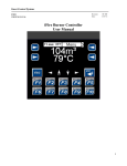
The logger’s keypad and display ___________________________________________________________ 12
Using the logger’s keypad and display_____________________________________________________ 12
Summary of keypad functions ___________________________________________________________ 13
Resetting the logger ____________________________________________________________________ 15
Coldbooting ________________________________________________________________________ 15
Warm reset _________________________________________________________________________ 16
Password ____________________________________________________________________________ 17
Setting the logger’s clock ________________________________________________________________ 18
Using Ls2Win _______________________________________________________________________ 18
Using the keypad/display_______________________________________________________________ 18
Chapter 2 : Interrogating the DL2e logger _________________________________________19
Logger status _________________________________________________________________________ 19
Using Ls2Win _______________________________________________________________________ 21
Using the keypad/display_______________________________________________________________ 21
Sensors status _________________________________________________________________________ 22
What the Sensors status provides _________________________________________________________ 22
Using Ls2Win _______________________________________________________________________ 23
Using the keypad/display_______________________________________________________________ 23
Error status ___________________________________________________________________________ 24
Using Ls2Win _______________________________________________________________________ 26
Using the keypad/display_______________________________________________________________ 26
Chapter 3 : Starting and Stopping Logging _________________________________________27
Starting logging________________________________________________________________________ 27
Using Ls2Win _______________________________________________________________________ 27
Using the keypad/display_______________________________________________________________ 28
Stopping logging_______________________________________________________________________ 29
Using Ls2Win _______________________________________________________________________ 29
Using the keypad/display_______________________________________________________________ 29
Chapter 4 : Collecting and Erasing Logged Data_____________________________________30
Data collection options __________________________________________________________________ 30
DL2e Hardware Reference
Page iii
Contents
Using Ls2Win _______________________________________________________________________ 32
Outputting data directly to a printer_________________________________________________________ 33
Preparation _________________________________________________________________________ 33
Checking printer operation _____________________________________________________________ 33
Using the keypad/display ______________________________________________________________ 34
Auto-printing _______________________________________________________________________ 35
To stop auto-printing: _________________________________________________________________ 35
Using other data collection devices _________________________________________________________ 36
Data integrity checks __________________________________________________________________ 36
Handshaking________________________________________________________________________ 36
Continuous data collection as a backup ____________________________________________________ 37
Erasing data from the logger’s memory ______________________________________________________ 37
Using Ls2Win _______________________________________________________________________ 37
Using the keypad/display ______________________________________________________________ 37
Chapter 5 : DL2e Logger Hardware ______________________________________________39
Power supplies ________________________________________________________________________ 41
Internal battery operation ______________________________________________________________ 41
Lithium cell_________________________________________________________________________ 42
External power supplies _______________________________________________________________ 43
WARNINGS________________________________________________________________________ 44
Rechargeable battery pack, type LBK1 ______________________________________________________ 46
Assembling the battery pack ____________________________________________________________ 47
Fitting the battery pack to the logger ______________________________________________________ 47
Recharging _________________________________________________________________________ 47
IMPORTANT WARNINGS ____________________________________________________________ 48
Overload protection___________________________________________________________________ 48
Electrical mains environment _____________________________________________________________ 48
Display (contrast) ______________________________________________________________________ 49
Installing IC’s _________________________________________________________________________ 49
Communication parameters_______________________________________________________________ 50
Communication cables __________________________________________________________________ 51
The logger’s RS232 serial port configuration________________________________________________ 51
Computer cables _____________________________________________________________________ 52
Cables for printers ____________________________________________________________________ 52
Testing communication__________________________________________________________________ 53
Terminal mode ______________________________________________________________________ 53
Echo test___________________________________________________________________________ 53
Diagnosing faults ____________________________________________________________________ 54
Other causes of communication problems __________________________________________________ 54
Field installation _______________________________________________________________________ 55
Temperature ________________________________________________________________________ 55
Moisture ___________________________________________________________________________ 55
Maintenance, Storage, Repairs and Recalibration ______________________________________________ 57
Maintenance ________________________________________________________________________ 57
Storage ____________________________________________________________________________ 57
Repairs ____________________________________________________________________________ 57
Recalibration service__________________________________________________________________ 57
Warranty and Service ___________________________________________________________________ 58
Terms and Conditions of Sale ___________________________________________________________ 58
Service and Spares ___________________________________________________________________ 58
Technical Support ____________________________________________________________________ 59
Chapter 6 : Sensors and Input Cards _____________________________________________60
Overview of electrical measurement techniques _______________________________________________ 60
Digital signals _______________________________________________________________________ 60
Analogue signals _____________________________________________________________________ 60
Analogue input cards _________________________________________________________________ 61
Supplementary cards __________________________________________________________________ 61
Voltage measurements ________________________________________________________________ 61
Current measurement _________________________________________________________________ 62
Page iv
DL2e Hardware Reference
Contents
Resistance measurements ______________________________________________________________ 62
Measuring small changes in resistance_____________________________________________________ 63
Potentiometric measurements ___________________________________________________________ 63
Power supplies to sensors (and other devices) _______________________________________________ 64
Summary of cards and on-board channels __________________________________________________ 65
Summary of connections for analogue measurements _________________________________________ 66
Input and supplementary cards ____________________________________________________________ 67
Installing input cards __________________________________________________________________ 67
Removing and fitting ribbon cables _______________________________________________________ 68
Analogue Input Card, type LAC1 __________________________________________________________ 69
15-ch mode _________________________________________________________________________ 69
30-ch mode _________________________________________________________________________ 69
Input protection (15-ch and 30-ch modes) __________________________________________________ 70
Analogue Input Card, type ACD1 __________________________________________________________ 73
4-Wire Card, type LFW1_________________________________________________________________ 75
Attenuator Card, type LPR1 Input Protection Card, type LPR1V ___________________________________ 80
AC Excitation Card, type ACS1 ___________________________________________________________ 83
Voltage, single-ended ___________________________________________________________________ 86
Voltage, differential_____________________________________________________________________ 89
Voltage, up to ±50V DC _________________________________________________________________ 92
Earth loops and common mode voltages _____________________________________________________ 95
Earth loops _________________________________________________________________________ 95
Common mode voltages _______________________________________________________________ 96
Current ______________________________________________________________________________ 98
Resistance, 2-wire _____________________________________________________________________ 101
Resistance, 3-wire _____________________________________________________________________ 104
Resistance, 4-wire _____________________________________________________________________ 106
Selecting a suitable excitation current ______________________________________________________ 108
Bridge measurements __________________________________________________________________ 109
Potentiometer ________________________________________________________________________ 113
Digital inputs, and Counter Card type DLC1 _________________________________________________ 115
Timing accuracy ____________________________________________________________________ 118
Providing additional digital status channels ________________________________________________ 120
Relay channels _______________________________________________________________________ 121
Intermittent logging - using relay and event trigger combinations _________________________________ 126
Requirement _______________________________________________________________________ 126
Explanation ________________________________________________________________________ 126
Manual control of logging _____________________________________________________________ 126
Example Program and Wiring for Intermittent Logging _______________________________________ 127
Thermistors__________________________________________________________________________ 128
Using thermistors with the logger _______________________________________________________ 128
Platinum Resistance Thermometer and other RTDs ____________________________________________ 131
Using PT100 And other RTDs with the DL2e logger _________________________________________ 131
Thermocouples _______________________________________________________________________ 133
Appendices__________________________________________________________________136
Appendix A : DL2e Technical Specifications ______________________________________ 138
Logging ____________________________________________________________________________ 138
Logging interval and speed ____________________________________________________________ 138
Input channels ______________________________________________________________________ 138
Analogue inputs ______________________________________________________________________ 138
Analogue Card, LAC1________________________________________________________________ 138
Analogue Card, ACD1________________________________________________________________ 138
4-Wire Card, LFW1__________________________________________________________________ 138
Attenuator Card, LPR1 _______________________________________________________________ 140
Input Protection Card, LPR1V__________________________________________________________ 140
Digital inputs and outputs _______________________________________________________________ 141
Digital inputs ______________________________________________________________________ 141
Relay outputs ______________________________________________________________________ 141
Counter Card, DLC1 _________________________________________________________________ 141
DL2e Hardware Reference
Page v
Contents
Other specifications ___________________________________________________________________ 142
Rechargeable battery pack LBK1 _________________________________________________________ 143
Electro-Magnetic Compatibility __________________________________________________________ 143
Appendix B : Accuracy of logger readings ________________________________________ 144
Adding errors from different sources _____________________________________________________ 144
Analogue accuracy ____________________________________________________________________ 145
Voltage reading accuracy _____________________________________________________________ 145
Resistance reading accuracy ___________________________________________________________ 146
Calculation of logger analogue accuracy: a worked example ___________________________________ 147
Arithmetic accuracy ___________________________________________________________________ 148
Analogue sensors: linear conversion to engineering units _____________________________________ 148
Counter and frequency sensors: linear conversion to engineering units ___________________________ 148
Linearisation errors __________________________________________________________________ 149
Appendix C: Calculating the speed of data readings _________________________________ 150
Appendix D : Resident linearisation tables ________________________________________ 152
Thermistor tables _____________________________________________________________________ 153
Thermocouple tables___________________________________________________________________ 154
Appendix E : Identifying components on cards ____________________________________ 155
Index ______________________________________________________________________156
Page vi
DL2e Hardware Reference
Hardware Reference
About this manual
Hardware Reference
About this manual
This manual contains information about:
•
using the keypad on the front panel
•
power supplies and the rechargeable battery pack
•
setting internal switches and rebooting,
•
installing additional cards and components,
•
connecting sensors
•
connecting cable assemblies
•
communications cables and modems
•
sensor linearisation tables
•
accuracy and technical specifications
•
maintenance, storage, repairs and guarantee.
It also contains general guidance on the scope and application of the measurement
techniques supported by the logger.
Other Documents and Help.
See the "Getting Started" manual for:
Separate Contents and
Indexes exist for :
- each on-line Help,
- Hardware Reference,
- Getting Started.
So keep searching!
DL2e Hardware Reference
•
Installation instructions.
•
A Guided Tour for an introduction to some of the logger’s facilities.
•
Learn the basics of logger operation in the Tutorial.
•
A brief introduction to features not covered in the tutorial.
View the on-line Help or press F1 in each of the Ls2Win applications for help on
using the Windows software:
Sensor Application Notes, including wiring instructions, are provided on-line in the
sensor library in the DL2Program Editor.
You can print off individual on-line Help topics.
Use all the Indexes and Contents Lists - in this manual, Getting Started, and in the
on-line Help for Ls2Win. They are all different.
Page 7
Hardware Reference
About this manual
Note the following specialist, technical manuals:
Page 8
•
DL2e Technical Reference manual, consisting solely of printed circuit board
schematics for the various cards and accessories.
•
DL2e Programmers Guide. This contains terse information for programmers
about communicating with the logger. It is provided on your installation disk as a
text file.
DL2e Hardware Reference
Hardware Reference
About the DL2e Logger
Waking and sleeping
Chapter 1 : About the DL2e Logger
The DL2e logger unit contains all the hardware required for capturing and storing data
from a wide variety of different types of sensor, under most environmental conditions.
It runs an internal logging program that is set up by the user, and tells the logger how
and when to acquire data.
The logger’s front panel keypad and display gives control over the essential features
which are needed for field operation away from a computer, such as starting and
stopping the logger, displaying current readings, providing status reports, and
outputting logged data to a local printer or intermediate collection device.
The Windows software Ls2Win also provides control over all the features available
from the front panel keypad. It also is used to program the logger. This involves
choosing the number of channels to be logged, the types of sensor and appropriate data
conversions, the rate at which each channel is to be logged, and action to be taken on
out-of-limits conditions.
It also provides a range of other features that are not available from the keypad, such as
timed start, triggering on events, collecting and manipulating logged data.
Password facility
Certain logger functions are protected from unauthorised use by a password facility.
This is set up in the logging program using the DL2e Program Editor, which is part of
Ls2Win. See also the on-line Help.
Waking and sleeping
The DL2e Logger can exist in one of two states, known as ‘awake’ and ‘asleep’,
corresponding to high and low levels of activity.
Awake
When awake all of the logger’s circuitry is powered up and all its functions are active.
The logger is awake during a LOG, WARM-UP or EVENT (see opposite), and while
communicating via its RS232 port, or performing any of the tasks controlled from its
keypad. There is normally a message displayed on the logger’s display, and this is the
simplest way to recognise when the logger is awake. Typical current consumption in
the awake state is 40mA.
Asleep
When asleep a minimum number of components are powered up, notably the clock (to
keep time), memory (to conserve data), and circuitry which enables the logger to be
woken. The logger’s display is always blank when the logger is asleep. Typical current
consumption in the asleep state is 40µA.
Waking the logger
The logger wakes of its own accord whenever required to LOG, EVENT, or WARMUP. See Logging, opposite.
To use the logger’s keypad functions press the WAKE key.
An incoming signal at the logger’s RS232 port wakes the logger. This occurs when you
communicate with the logger from your PC using the DL2 Control Panel, which is
installed on your desktop as part of Ls2Win.
DL2e Hardware Reference
Page 9
About the DL2e Logger
Logging
Hardware Reference
Putting the logger to Sleep
The asleep state is the logger’s preferred state, with low power consumption for battery
conservation. The logger automatically sleeps if it has woken specifically to LOG,
EVENT, or WARM-UP (i.e. provided that it is not also busy communicating or
operating under keypad control).
In other situations, the logger autosleeps if it receives no input from a user (i.e. a key
press, or communication via its RS232 port) within a reasonable period of time.
There is no manual method of putting the logger to sleep from the keypad: the logger is
simply left to autosleep.
The logger can be put to sleep by a warm reset (see page 16), but this method is not
recommended for routine use.
Autosleep
The logger autosleeps in the following conditions:
After 10 seconds when displaying the Keypad main menu if no key is pressed.
Within a few seconds if the logger is woken by noise at its RS232 port, such as may
occur if the power supply to a printer or computer is switched while connected to the
logger. The logger discriminates between noise and a genuine attempt to communicate
by waiting a few seconds for further signal.
After one or two minutes if no user input occurs (i.e. a key press or communication
signal) at any other time.
Autosleeping can be disabled when using the ‘auto-print’ feature.
See "Auto-printing" on page 35.
Logging
After starting logging, the logger normally autosleeps, and then wakes when required to
take readings from sensors or to switch warm-up relays. The logger is said to be
‘logging’, even though it is not actually recording data at a given instant, for example in
messages such as ‘logging started..’ or ‘already logging’.
LOG, EVENT, WARM-UP
While logging, recording of data may be initiated either by the logger’s internal clock
(readings taken at regular intervals, known as ‘timed’ data), or by a signal on a channel
programmed as a data trigger (or ‘event triggered’ data). Switching of a warm-up relay
is controlled by the logger’s clock.
These tasks take priority over keypad functions and communication. When carrying out
one of these ‘priority tasks’, the logger flashes up a message on its display to indicate
that other logger functions are temporarily suspended.
The respective messages are:
•
For recording timed data:
LOG
•
For recording event triggered data:
EVENT
•
Page 10
For switching a warm-up relay:
DL2e Hardware Reference
Hardware Reference
About the DL2e Logger
Logging
WARM-UP
The logger is said to be performing a LOG, EVENT or WARM-UP.
While communicating with the logger, you may notice appreciable delays in
responding to your key presses while the logger is busy performing a priority task. If
the logger is programmed to log timed data very frequently you may find it difficult to
establish communication with the logger, and data collection may be appreciably
slower than normal.
Occasionally the logger may attempt to display the message off screen (off the edge of
the logger’s display). This is unusual, most likely to occur when the logger is
displaying a General status report. You may then notice a delay in keypad operation
without any message being displayed.
Conflicting priority tasks
It is possible for an event trigger to occur while the logger is busy logging timed data,
and for timed data to become due while the logger is servicing an EVENT. If so, the
logger completes the first priority task before tackling the second one.
As a result, there may be a discrepancy between the time recorded by the logger in its
data file, and the actual time when an EVENT occurred, or when data was actually
logged (see "Timing accuracy" on page 118 for details).
If a LOG becomes due while the logger is still working on a previous LOG, an over-run
occurs (see " Over-runs" on page 26 for details).
EVENT detection is disabled on an event trigger channel while the logger is busy
servicing a previous EVENT on the same event trigger channel. The logger may miss
events occurring in short succession.
DL2e Hardware Reference
Page 11
About the DL2e Logger
The logger’s keypad and display
Hardware Reference
The logger’s keypad and display
Using the logger’s keypad and display
To use the logger’s keypad, wake the logger by pressing WAKE.
You must press WAKE while the logger is asleep. Any message on the screen indicates
that the logger is already awake, for example communicating or performing a LOG.
Disconnect any serial communication cable and allow the logger to autosleep (if
autosleeping has not been disabled). In emergency try a warm reset or, as a last resort,
coldboot the logger (see "Coldbooting" on page 15).
On its display, the logger echoes the key press:
<WAKE>
Keypad main menu
The logger displays General Status and Malfunction Reports (see "Logger " on page 19
and page "Error status" on page 24), followed by a message, known as the Keypad
main menu:
Press key if
required..
Keypad functions
You can now press any key to enter one of the logger’s seven ‘keypad functions’. The
keypad functions are named after the logger’s seven keys, and are summarised
opposite.
Note that you can curtail the General Status and Malfunction Reports at any time by
pressing one of the keys. If you hold the key down, you can also omit the main menu
message and go directly into one of the keypad functions.
On entering a keypad function, for example READ, the logger first confirms the key
press by displaying the name of the selected function.
<READ>
On exiting any of the keypad functions, the logger always returns to the Keypad main
menu. Note however, that the logger may autosleep if left too long without a key press.
There is no keypad function for putting the logger to sleep. The logger autosleeps (see
"Autosleep" on page 10).
Entering information
Some of the keypad functions require you to enter information, for example date and
time, password or a selection from a menu. To do so, use σ and/or θ until the value or
option that you require comes up on the display. To accept the displayed option press
the key corresponding to the keypad function that you are using.
The logger displays a prompt such as:
Page 12
DL2e Hardware Reference
Hardware Reference
About the DL2e Logger
The logger’s keypad and display
use <UP> <DOWN>
& <SET TIME>..
Confirming a selection
Some of the keypad operations require confirmation before proceeding, for example
erasing data or stopping logging. To confirm, press the key for the keypad function that
you are using. In the example below, press START to execute the operation you
requested. Pressing any other key, or leaving the logger to autosleep, aborts the
operation.
The logger displays a prompt such as:
<START> confirms
other keys abort
Summary of keypad functions
The keypad functions are named after their corresponding keys: WAKE, σ,θ, READ,
SET TIME, START and PRINT.
WAKE
The WAKE function displays a General status report:
•
Battery voltage and expected life
•
Current date and time.
•
Configuration name
•
Whether logging or not
•
Date and time of start and end of logging, if appropriate
•
Amount of memory installed and number of stored data.
•
Malfunction Reports: battery failed, memory filled and suspect data logged on any
channel.
See "Logger " on page 19 for details.
READ
The READ function is for checking a logging set up before or during logging:
•
Displays instantaneous values on input channels
•
Displays status of relay and event trigger channels.
•
Permits switching of relay channels under keypad control.
See page 23 for details.
SET TIME
The SET TIME function sets the time on the logger’s internal clock.
See "Setting the logger’s clock" on page 18 for details.
START
The START function starts and stops logging. See "Starting and Stopping Logging" on
page 27 for details.
PRINT
The PRINT function can be used to:
•
DL2e Hardware Reference
Print out data on a serial printer.
Page 13
About the DL2e Logger
The logger’s keypad and display
Hardware Reference
•
Output data in binary file format to a data collection terminal (not using Logger PC
Software).
•
Erase data.
See "Collecting and Erasing Logged Data" on page 30 for details.
σ
The σ function is for testing two-way serial communication, e.g. with a computer. See
"Error! Reference source not found." on page Error! Bookmark not defined. for
details.
θ
The θ function is for testing one way serial communication, e.g. with a printer. See
"Checking printer operation" on page 33 for details.
Page 14
DL2e Hardware Reference
Hardware Reference
About the DL2e Logger
Resetting the logger
Resetting the logger
Coldbooting
Coldbooting restores the logger to a known basic state with the following
consequences:
•
Any data stored in the logger is erased.
•
The logger carries out a RAM check, checking which RAM chip positions are
occupied, and whether any RAM chips are faulty.
•
The existing logging program is erased and the default configuration is installed.
•
Any Setup string for PRINT is erased.
XXXX See "Setup string for PRINT" in the on-line Help.
•
Auto-wrap (previously called the overwrite mode) is disabled.
See "Auto-Wrap" in the on-line Help.
The logger’s clock is not reset.
The logger automatically coldboots on waking if a new PROM is installed.
The logger must be coldbooted if:
•
RAM chips have been moved or installed
•
The logger has crashed irretrievably for any reason, and a warm reset (see
opposite) fails.
•
Input cards have been removed or installed, i.e. plugged into or out of the input
card stack.
The logger does not need to be coldbooted if only switches or ribbon cables have been
moved, or if attenuator or input protection cards types LPR1, LPR1V have been
installed.
To coldboot the logger
•
Open the logger’s case.
•
Hold down the ‘COLD BOOT’ and ‘STOP’ buttons on the main circuit board
(see Figure 2 - Main circuit board layout), and then -
•
Ø
if the logger is asleep, also press WAKE on the logger’s keypad,
Ø
if the logger is already awake, also press the ‘RESET’ button on the logger’s
main circuit board (see Figure 2).
The message ‘coldbooting..’ appears on the logger’s display, followed by a
sequence of reports as the logger checks RAM chips, installs a DEFAULT logging
program (described in Tutorial Lesson 3 in the Getting Started manual), and goes
to sleep.
Ensure that the sequence of reports above does occur. Any other type of message
indicates that the logger is not in fact coldbooting.
Note that the logger also coldboots if the logger wakes for any reason while the ‘COLD
BOOT’ and ‘STOP’ buttons are held down.
In extreme circumstances, you may have to remove all power from the logger before
coldbooting. Disconnect any external power supply, remove the logger’s internal
batteries, gently lift the spring terminal from the top of the lithium cell (see "Lithium
cell" on page 42) with a fingernail, and hold for 10 seconds. Replace the logger’s
batteries and coldboot as described above.
DL2e Hardware Reference
Page 15
About the DL2e Logger
Resetting the logger
Hardware Reference
Warm reset
A ‘warm reset’ puts the logger to sleep without destroying any information in the
logger’s memory (data, configuration, etc.). The logger can be woken to resume normal
operation after a warm reset. Warm reset is not as drastic as coldbooting. Try it in
preference to coldbooting if the logger crashes and gets stuck in an awake state.
Coldboot only as a last resort if a warm reset fails.
The logger normally autosleeps of its own accord and warm reset should not be used to
routinely put the logger to sleep. In particular, beware of resetting the logger while it is
in the middle of a LOG, EVENT or WARM-UP. This may interfere with the setting of
the logger’s clock in preparation for the next LOG, and have an unpredictable effect on
logging of timed data.
To carry out a warm reset
Page 16
•
Open the logger’s case.
•
Press and release the ‘RESET’ button (see Figure 2). When the button is released,
the logger’s display goes blank.
•
Repeat if necessary.
DL2e Hardware Reference
Hardware Reference
About the DL2e Logger
Password
Password
The DL2e Logger has a password facility for preventing loss of data or interruption of
logging due to unauthorised use of the logger’s keypad or PC software.
The password is set up as part of the logging program.
Once the logger is programmed with a password, the user has to enter it in order to
perform the following operations:
•
erase data from the logger’s memory
•
stop logging
•
start logging, if data is stored in the logger
•
re-program the logger, if data is stored in the logger
The password does not need to be entered in order to use any other keypad or software
function.
To program the logger with a password
Open or create a logging program using the DL2 Program Editor.
Enter up to 8 alphabetic characters in the Password box.
Send the program to the logger in the normal way.
Note that the logger’s keypad and display only offers upper case alphabetical characters
and spaces. If your password contains lower case or non-alphabetical characters you
cannot enter it from the logger’s keypad. (You can do this using any PC software.)
When prompted for a password
Using Ls2Win
DL2 Control Panel pops up the Password dialog, which prompts you to enter the
logger’s password.
Remember to use upper case or you will be locked out from using some of the Keypad
functions.
Using the keypad/display
When a password is required, a prompt appears on the top line and the cursor moves to
the left position on the bottom line.
password..?
_
Use σ and θ to cycle through the alphabet.
When the correct character appears, press the key corresponding to the keypad function
you are using: PRINT if erasing data, START if starting or stopping logging. The
cursor will move to the next position.
Enter 8 characters. If the password has less than eight characters, enter spaces to make
up 8 characters. To enter a space, press PRINT or START, as appropriate, without
pressing σ or θ.
Remarks
You can recall the logger’s current password by retrieving the logging program from
the logger.
DL2e Hardware Reference
Page 17
About the DL2e Logger
Setting the logger’s clock
Hardware Reference
Setting the logger’s clock
The logger has an internal clock that marks the date and time of all logged data. The
date and time can be set either from the program or from the front panel keypad. You
cannot set the clock while the logger is logging.
Leap Years
The logger does not keep track of years and cannot identify leap years. February is
always assumed to have 28 days. In a leap year, the logger’s date has to be set to the
correct date manually after 29th February.
Using Ls2Win
See the on-line Help in the PC's DL2 Control Panel program.
Using the keypad/display
At the Keypad main menu, press SET TIME.
The logger displays the following messages:
required..
<SET TIME>
use <UP> <DOWN>
& <SET TIME>
The logger displays the date and time.
& <SET TIME>
date: 28-01
The date is in European (day-month, dd-mm) or American (month-day, mm-dd) format,
depending on the setting of the ‘50/60’ switch (see "Electrical mains environment" on
page 48). The time is formatted as hours:minutes:seconds, hh:mm:ss.
Use σ and τ to adjust the value indicated by the cursor, and press SET TIME when the
displayed value is correct. The cursor then moves onto the next field. Note that the first
value that you set is always the month, irrespective of the date format.
The logger’s clock is actually set at the moment you press SET TIME to set the number
of seconds.
date: 28-01
time: 15:29:30
Page 18
DL2e Hardware Reference
Hardware Reference
Interrogating the DL2e logger
Logger status
Chapter 2 : Interrogating the DL2e logger
This chapter describes facilities that allow you to examine the current state of the
logger.
Status information is supplied on the following:
•
Logger, including battery voltage, date and time, logging program name, and
memory status.
•
Sensor channels, comprising instantaneous readings on input channels and status of
relay and event trigger channels. If using the logger’s keypad, relay channels can
also be exercised (i.e. turned on and off for testing purposes).
•
Datasets, including the amount of memory used and available
•
Errors (malfunctions reports), i.e. whether any problems have occurred while the
DL2e Logger has been logging, including full memory, battery failure, and suspect
data on input channels. Malfunction reports can be deleted so that only new
malfunctions get reported on the next occasion.
Either WAKE the logger from the Front Panel, or run a DL2 Control Panel on your PC.
General Status Report
A general status report appears transiently on the Front Panel when you wake the
logger. This information may also be viewed in the DL2 Control Panel on your PC.
See also the on-line Help available in each of the following component programs of the
Windows software Ls2WIN:
•
DL2 Program Editor - to create and edit logging programs.
•
DL2 Control Panel - to control and monitor the logger
•
Dataset Import Wizard - to retrieve logged data into Microsoft Excel.
•
DL2 Dataset Viewer - to view raw data files once saved to your PC.
Logger status
Logger status information is displayed on the Logger and Datasets panels, in the DL2
Control Panel on your PC.
It also appears transiently on the DL2e Front Panel as part of the general status report
when you wake the logger.
PROM version
The PROM version is only shown on your PC - in the Logger panel in the DL2 Control
Panel. It does not appear on the logger’s Front Panel Display.
Battery voltage and % life expectancy
The reported battery voltage is the voltage available to power the logger.
The voltage available to power the logger is not always the full battery or external
power supply voltage, being reduced by a diode drop (approximately 0.6V) in the
following cases:
•
If the logger is powered from an external power supply
•
If the logger is powered from its internal batteries with the power supply selector
switch set to ‘EXTERNAL’.
The reported battery voltage is intended as a guideline only. Fluctuations may occur
due to polarisation effects in the logger’s internal alkaline cells. In particular, the
batteries appear to recover during a long period of inactivity, but their voltage then falls
rapidly to its previous level when the logger is awake.
DL2e Hardware Reference
Page 19
Interrogating the DL2e logger
Logger status
Hardware Reference
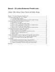
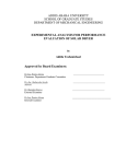
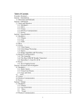
The battery life is calculated on the basis of a linear interpolation between 7V (0% left)
and 8.5V (99% left) and applies to alkaline cells only. A battery voltage in excess of
10V is reported as >10V, and voltages in excess of 8.5V are reported as 99% left.
Figure 1 - Battery life interpolation
Date and time
The formatting of the date is linked to the setting of the ‘50/60’ switch (see Figure 2 Main circuit board layout):
•
‘50’ gives European date formatting (i.e. day-month).
•
‘60’ gives American date formatting (i.e. month-day).
Leap years
The logger does not keep track of years, and cannot identify leap years. February is
always assumed to have 28 days. In a leap year you must re-set the correct date
manually after 29th February.
Program (or configuration) name
This is the name of the file containing the logging instructions that you download from
the PC to the logging program that is installed in the logger and which tells it when to
log, which channels to log, how to record results and so on. The Front Panel display
calls this the configuration, abbreviated to "config'n". In Ls2Win call this the logging
program.
Logging started
Shows the date and time when a command to start logging was issued. It is the date and
time of a key press (if logging has been started from the keypad), or a command issued
by means of the PC, and not the precise date and time of the first logged data:
•
For an immediate start, either using the PC or the keypad, there is a short delay
between issuing the instruction to start and the first logged data: the reported time
may be up to 2 seconds earlier than the time of the first logged data.
•
If the logger is set to start at a pre-set time, or set for a triggered start, there is
generally a longer time delay between issuing the instruction to start logging and
the first logged data.
Standing by
This message indicates that the logger is not yet logging, and contains no stored data
from a previous logging session.
Page 20
DL2e Hardware Reference
Hardware Reference
Interrogating the DL2e logger
Logger status
Logging stopped
Shows the date and time when logging stopped automatically (as a result of its memory
filling up or detection of a battery failure: see "Low battery" on page 41), or was
terminated from the keypad or PC. This may not necessarily be the same as the time
and date of the last logged reading.
RAM STATUS and
STORED DATA
The logger’s memory may be partitioned into up to three independent areas or
‘datasets’.
•
One area can be set aside for timed data (i.e. data stored at the regular time
intervals specified in the logging program).
•
Two areas can be set aside for event triggered data (that is data stored when events
are detected on event trigger channels) if channels 61 and 62 are programmed as
event trigger channels.
These areas of memory are referred to as TIMED RAM, TRIG/61 RAM and TRIG/62
RAM or datasets respectively, and their status is reported separately.
Note that:
•
1K is 1024 bytes, and that each reading requires 2 bytes of memory.
•
All TIMED RAM is available for data, for example 128K of TIMED RAM is
131072 bytes, and can store 65536 readings.
•
Event triggered data is stored with an additional 7 bytes of date and time
information for each repetition of an event triggered sequence, and the number of
event triggered data that can be stored in a given amount of memory is reduced
accordingly.
•
DL2 Control Panel also reports the number of data since data was last retrieved.
These readings can be retrieved from the logger separately. See the on-line Help
for details.
•
Auto-wrap mode allows the logger to continue logging timed data when TIMED
RAM fills up, by overwriting old data (See the on-line Help for details). Auto-wrap
mode status is only reported by Ls2Win.
See also the on-line help for the DL2 Control Panel program.
Using Ls2Win
The DL2 Control Panel displays logger status information. See also its on-line Help and
Lesson 2 in "Getting Started".
Using the keypad/display
At the Keypad main menu, or while the logger is asleep, press WAKE.
The status report consists of a sequence of messages, each of which is displayed for
approximately two seconds.
It can be curtailed at any point by pressing any key.
DL2e Hardware Reference
Page 21
Interrogating the DL2e logger
Sensors status
Hardware Reference
Sensors status
What the Sensors status provides
This shows the current status of all channels that have been programmed as sensors. It
can be displayed on your PC in the Sensors panel of the DL2 Control Panel, or on the
logger's Front Panel display, using the keypad READ function.
The DL2 Control Panel displays a single value for each channel.
The READ function continuously updates the displayed value for a single channel,
allowing sensor connections to be conveniently tested. Relay channels can be exercised
and event trigger channels can be tested prior to starting logging.
This information is independent of logging, and can be obtained before or while
logging with no interference to logged data.
Each channel is identified by a number, label, and sensor code (for input channels) or
by a channel function (for other non-input types of channel).
Input channels
The READ button on the Front Panel, or the Sensors panel in the DL2 Control Panel,
either gives an instantaneous reading in engineering units, or it gives an error message
if appropriate. See also: Error status on page 24 for interpretation of error messages,
and the additional notes below for counter and frequency channels.
Counter channels
If the logger is logging, the selected channel(s) show the accumulated count without
affecting logged data.
If the logger is not logging, the counter is reset to zero before returning a Channel
Report.
Using the READ function, an updated accumulating count is displayed.
DL2 Control Panel displays only a single value, and not an accumulating count. If not
logging, this is normally zero, unless you apply a high frequency input signal.
Frequency type channels
The logger samples frequency inputs over ½ second periods. Hence it has a resolution
of 2 Hz for this purpose (e.g. for an input signal of 1 Hz, the display alternates between
0 and 2 Hz). Note that this does not apply for logged data, when the resolution of
frequency channels corresponds to the selected sampling interval
Relay channels
The status of a relay channel (MAL, OUT and WRM functions) is either ON or OFF.
Using the keypad READ function, the relays can be exercised for testing purposes (see
"Using the keypad/display" on page 23).
Sensors powered through warm-up relays are normally only powered up during the
warm-up periods specified in the logging program.
To obtain valid readings from a ‘warmed-up’ channel, the warm-up relay has to
be switched ON.
Warm-up relays are aautomatically switiched ON when you select a channel and press
Read Now in the Sensors panel of the DL2 Control Panel.
Remember you must manually switch warm-up relays ON when using the keypad
READ function (see page 23).
Page 22
DL2e Hardware Reference
Hardware Reference
Interrogating the DL2e logger
Sensors status
On exiting the status report, warm-up relays are returned to the state required for
logging, i.e. ON in a warm-up period, OFF otherwise. However, if logging is in
progress, the logger switches warm-up relays OFF at the end of a warm-up period, even
if they have been switched ON for a Channel Report. If this occurs, you will see faulty
readings from warmed-up channels.
Event trigger channels
Event trigger channels are reported as being either a s-trigger (start trigger), or d-trigger
(data trigger), with a status SET or CLR (clear).
When SET, the channel detects events and the logger acts accordingly.
When CLR, the channel ignores events.
Both start and data trigger channels are CLR when the logger receives a program, and
become SET when logging is started.
When a start trigger detects an EVENT, the logger starts recording data and the start
trigger becomes CLR, ignoring any further events.
Data trigger channels remain SET until logging is stopped or event triggered memory
fills up.
Using Ls2Win
Sensor status information is displayed in the Sensors panel of DL2 Control Panel. See
also its on-line Help and Lesson 2 in "Getting Started".
Using the keypad/display
At the Keypad main menu press READ.
The logger displays the sensor code and label for channel 1, or the first programmed
channel (in numerical order) if channel 1 is not programmed).
ch reading units
1 TM1
cold-jn
After a pause, the sensor code and label are replaced with a reading in engineering
units, or by an error message if the sensor is faulty or incorrectly connected.
ch reading units
1_ 20.95 deg C
Error messages may be o/s limits (outside limits), over-range, or noisy. These
conditions are discussed in detail on page "Sensor malfunctions" on page 25.
ch reading units
1_ o/s limits
The display is up-dated regularly until:
•
you press σ or τ to move on to another channel
•
you press READ to exit the READ function, and return to the Keypad main menu
•
the logger autosleeps
To change channels
Press σ or τ.
The reading on the next (or previous) programmed channel in numerical order will be
displayed.
1 20.95 deg C
2_ 999.9 ohm
Note: Even if two channels are displayed, only the channel marked by the underline
cursor is updated (i.e. channel 2 in this example).
DL2e Hardware Reference
Page 23
Interrogating the DL2e logger
Error status
Hardware Reference
Fast scrolling
Hold down σ or τ for fast scrolling through the channels.
Exercising relay channels
When you move onto a relay channel, the logger initially displays its status, and then
switches the relay between ON and OFF states at 2s intervals.
When σ or τ are pressed to move onto another channel, the relay remains switched in
the state last displayed. You can use this feature to power up a sensor manually, which
during normal logger operation would need to be powered using the warm-up relay
(WRM) function.
On exiting the READ function, or when the logger autosleeps, the relays are returned to
their normal state (i.e. the state they would be in if they had not been switched by the
READ function).
Note that logging requirements take priority over manual operation of the relays. If the
logger wakes to LOG or WARM-UP, it will override any manual settings of a relay. In
particular, the logger will not allow a warm-up relay to be switched off manually during
a warm-up period preceding a reading.
Testing event trigger channels
An event trigger channel in the CLR state does not normally detect events. When
reporting its status, the logger activates the trigger in a test mode. Events are then
detected and an EVENT message displayed, but the normal trigger function remains
disabled.
When finished...
Press READ to return to the Keypad main menu.
Error status
During logging, the logger detects and acts on four categories of malfunction:
•
Battery failure
•
Memory full
•
Sensor malfunctions
•
Over-run errors
The action taken by the logger on encountering each of these malfunctions and
associated malfunction reports is described in "Sensor malfunctions" below.
The logger’s WAKE function and the Errors panel in the PC's DL2 Control Panel
reports battery, memory and sensor malfunctions (but not over-runs).
Battery failure
The logger reads the battery voltage each time it wakes. If the voltage available to
power the logger is less than 7.0 Volts:
•
The logger briefly displays battery failure on its display.
•
If logging, the logger stops logging, compiles a malfunction report and switches
the malfunction-warning relay (if programmed). This is to conserve any remaining
battery life and avoid any risk of corrupting or losing logged data.
•
The logger autosleeps.
Remarks
The logger can only perform this routine if there is enough power available for the
logger to wake. If the power supply becomes completely disconnected, the logger will
be unable to take any action. On reconnection of the power supply, the logger will fail
to report battery failure. If logging, the most likely outcome is a series of over-run
errors as the logger attempts to catch up on lost logging opportunities.
Page 24
DL2e Hardware Reference
Hardware Reference
Interrogating the DL2e logger
Error status
The mechanism for detecting battery failure is not the same as for reading the battery
voltage when reporting Logger status. The logger may not detect a battery failure even
though it reports a battery voltage less than 7V, or the logger may have detected a
battery failure, while reporting a battery voltage greater than 7V (due to battery depolarisation).
Memory full
If an area of the logger’s memory (TIMED, TRIG/61, TRIG/62) fills up, the logger:
•
Briefly displays the message memory full.
•
Stops logging data of the relevant data type (TIMED, TRIG/61 or TRIG/62).
•
Compiles a malfunction report.
• Switches the malfunction warning relay (if programmed).
If all areas of the logger’s memory are full, the logger also stops logging. This is
reported on the Logger panel of the PC's DL2 Control Panel and in the status report
displayed on the Front Panel.
Sensor malfunctions
The logger detects three categories of sensor malfunction: over range, noisy and outside
limits. If they occur during a channel report, they are simply reported in error messages.
On detecting a sensor malfunction while logging data, the logger takes the following
action:
•
Flags the logged data with the appropriate flag (see on-line Help).
•
Compiles a malfunction report, indicating the type of sensor malfunction, and, if it
is the first malfunction recorded for that particular channel, the date and time. Note
that the malfunction report is more specific than the flags attached to data or error
messages displayed in the Sensors status report:
• Switches on the malfunction warning relay (if programmed).
Note : The logger cannot detect errors whist issuing a sensors/channel status report.
That is, data are not flagged and the malfunction report and malfunction warning relay
are not affected by malfunctions detected during a Sensors status report, even if the
logger is logging.
Over range
An over range condition occurs if:
•
On analogue channels, the logger’s full scale input range of ±2.096 Volts has been
exceeded (for resistance channels this is equivalent to 1048 kΩ, 104.8 kΩ, 10.48
kΩ, and 1048 Ω for excitation currents of 2, 20, 200, 2000 µA respectively).
•
On counter channels, a count of 65472 has been exceeded.
•
On averaged channels, the accumulated total of readings within the averaging
period has exceeded the logger’s arithmetical capacity, 2x10⁹ µV, or for non-linear
sensors, 2 x 10⁷ engineering units. This is reported as ave too large in
malfunction reports.
•
For non-linear sensors, the input falls outside the linearisation table. This is
reported as outside table in malfunction reports.
•
A valid cold-junction temperature is not available for a thermocouple channel that
requires a cold-junction reference. This is reported as bad cold-jn. in malfunction
reports.
Noisy
The logger will not autorange both up and down during a single reading. It records a
value in the less sensitive range and flags the reading as noisy.
Outside limit
Upper and lower limits for valid readings can be set to any reasonable level and will
usually be the most sensitive test for malfunction (see Valid Range in the on-line Help).
DL2e Hardware Reference
Page 25
Interrogating the DL2e logger
Error status
Hardware Reference
Outside limits readings are reported as outside limit in malfunction reports, and as o/s
limits in Channel Reports.
Over-runs
Over-runs occur when storing timed data if the logger finds that the time for its next
LOG has already passed. Whenever this happens, the logger saves time by storing
copies of previous readings (or adding them to averages etc.) instead of taking new
readings. This is very unlikely to occur in normal use, but might happen if:
•
The logger is programmed to read faster than it is able to, e.g. 60 thermistors every
5 seconds. See Appendix C for information about logging speed.
•
The logger is programmed to read close to the limits of its speed and an unusual
coincidence causes it to be exceptionally slow, e.g. all channels requiring
autoranging on the same LOG (as can happen on the very first LOG).
•
The logger is programmed to log timed and event triggered data, and the length of
time spent recording triggered data is sufficient to cause it to over-run on timed
readings.
Storing faulty data
Readings involving either sensor malfunctions or over-runs are recorded with lower
resolution (10 bits instead of 12 bits). See also the on-line Help.
Faulty readings do not contribute to the minimum and maximum values in data file
headers. See also the on-line Help.
If problems occur with individual readings on a channel employing data compression,
the resulting compressed values are flagged accordingly.
Deleting malfunction reports
Malfunction reports can be deleted from the logger’s memory, so that in future the
logger reports fresh occurrences of malfunctions only. Deleting malfunction reports
also resets the malfunction warning relay to OFF, if programmed. Any flagged data
stored in the logger’s memory remain flagged.
Using Ls2Win
The DL2 Control Panel displays error status information in the Errors panel. See also
its on-line Help.
Using the keypad/display
Displaying malfunction reports
Press the WAKE key to wake the logger. BATTERY FAILURE, MEMORY FILLED
and sensor malfunction reports are then displayed after the logger status report.
To end malfunction reports, at any time, press any key on the logger’s keypad.
To delete malfunction reports
After displaying the malfunction reports, the logger offers the option of deleting them.
to delete report_
Press WAKE to delete the malfunction reports, or any other key if you want to retain
them in the logger’s memory.
<WAKE> confirms
other keys abort
Page 26
DL2e Hardware Reference
Hardware Reference
Starting and Stopping Logging
Starting logging
Chapter 3 : Starting and Stopping Logging
Starting logging
Logging may be started from the keypad, or using the PC's DL2 Control Panel
program. Three different methods of starting the logger are available:
•
Immediate start
•
Pre-set time start
•
Event triggered start
Any data stored in the logger is erased on starting. The logger issues a warning to
remind you that data is to be erased. If the logger is programmed with a password, you
will have to enter the password in order to proceed.
As soon as the logger receives the instruction to start logging, it considers itself to be in
a logging condition. The Logger Status indicates that Logging has started. Resetting the
logger’s clock is not permitted, even if the logger has not yet logged any data. In
particular, note that this applies to timed and event triggered starts, when a considerable
time interval can elapse between issuing the instruction to start logging and actually
storing the first data.
The logger stores the time of receiving the instruction to start. This is the time reported
in the Logger panel of the DL2 Control Panel (see "Logger " on page 19), and does not
coincide precisely with the time of the first logged data (even for immediate start).
Immediate Start
This method of starting occurs if logging is started from the keypad, or if the immediate
start option is selected using the PC. The logger sets its clock to log timed data as soon
as possible after receiving the command to do so. There may be a 2-second delay
between issuing the command and the first logged timed data.
If a start trigger channel has been programmed, event triggered starting occurs instead
(see below).
To start logging at a pre-set time
Using the PC, the logger can be made to start at a pre-set date and time (for example,
on 31st January at midnight).
Event triggered start
The logger can be armed to start logging when a signal is detected on channel 61.
The logger must be programmed with channel 61 as a start trigger channel (see on-line
Help). When started from the logger’s keypad, or using the immediate start option via
the PC, the logger will delay logging until it receives a signal on channel 61.
Note that this is different from the action of a data trigger. After an event triggered start,
the logger proceeds logging as if an ordinary immediate start had occurred, acquiring
timed data at regular intervals, with no further inputs required on the start trigger
channel. A data trigger causes the data to be logged whenever an input is detected on
the data trigger channel, in parallel with timed data.
Using Ls2Win
Click Start or Re-start in the Logger panel of DL2 Control Panel, then make a selection
from the available options in the Start Logging dialog. See also the on-line help.
DL2e Hardware Reference
Page 27
Starting and Stopping Logging
Starting logging
Hardware Reference
Using the keypad/display
Event triggered start only
For a triggered start, first program channel 61 as a start trigger (see on-line Help). Then
proceed as for Immediate start.
Immediate start
At the Keypad main menu, press START.
<START>
If the logger is already logging, you are asked if you want to stop logging (see Stopping
Logging, on page 29).
already logging
to STOP:
If data exists from a previous logging session, you will be asked if you want to erase it.
28 readings
to be erased
If the logger contains data and is programmed with a password, you will be prompted
to enter it.
password..?
The logger prompts you to press START again to confirm that you want to start logging
and erase any previous data. Press any other key if you decide not to start logging.
<START> confirms
other keys abort
If the logger has been programmed with a Start trigger channel, a message appears
indicating that the start trigger is set, i.e. awaiting a signal to start logging.
start trigger
set..
If there is no start trigger channel, the first LOG starts after 1 to 2 seconds.
other keys abort
logging started
The message LOG appears briefly, indicating that a set of timed readings has been
taken.
other keys abort
LOG ing started
Page 28
DL2e Hardware Reference
Hardware Reference
Starting and Stopping Logging
Stopping logging
Stopping logging
Logging may be stopped by using either the front panel keypad or via the PC. There is
also an internal ‘STOP’ button. Note there are no facilities using an event trigger to
stop logging, nor for stopping at a pre-set time.
Stopping logging is protected by passwords (except if the ‘STOP’ button is used).
There is no need to stop logging in order to collect logged data, or to use any other
Windows software or front panel function.
Logging stops automatically in the event of a battery failure. If the memory available
for a data type (TIMED, TRIG/61, TRIG/62) fills up, the logger stops logging data of
that data type (but note that overwrite mode allows the logger to continue logging timed
data).
Using Ls2Win
Click Stop in the Logger panel of DL2 Control Panel.
Using the keypad/display
At the Keypad main menu, press START.
<START>
A message indicates that the logger is already logging. If this message does not appear,
then this procedure will start logging instead of stopping it (see the previous section).
already logging
to STOP:
If the logger contains stored data and is also programmed with a password, you are
prompted to enter it.
password..?
Press START again to confirm that you want to stop logging. Press any other key if you
decide not to stop logging.
<START> confirms
other keys abort
Logging stops after confirmation and the logger returns to the main menu.
logging stopped
Using the internal STOP button
Open the logger’s lid, and hold down the STOP button (see Figure 2 - Main circuit
board layout). While the STOP button is held down, do one of the following:
•
If the logger is asleep, wake the logger by pressing WAKE.
•
If the logger is already awake, press the RESET button (see Figure 2 - Main circuit
board layout).
Logging will also stop if the STOP button is held down when the logger wakes of its
own accord in order to log data.
This method of stopping logging is not protected by passwords.
DL2e Hardware Reference
Page 29
Collecting and Erasing Logged Data
Data collection options
Hardware Reference
Chapter 4 : Collecting and Erasing Logged Data
Data can be collected from the logger at any time during logging. There is no need to
stop logging.
Data output from the logger can be controlled either from the logger’s keypad, or from
your PC.
Data that you have collected can be erased from the logger’s memory to create space
for more data. By repeatedly collecting and erasing data, you can acquire as much data
as you like (regardless of the logger’s memory capacity) without interrupting logging.
You can collect data from the logger in the following ways:
•
Printing out data directly from the logger using a printer.
•
Using the Dataset Panel in the PC's DL2 Control Panel to collect data to a
computer file. Data files can be imported in to Microsoft Excel directly using
Dataset Import Wizard, or converted to comma separated ASCII (.dat) format files
which are suitable for importing into other data processing programs
•
Using the Data Import Wizard to import data directly into a Microsoft Excel
Spreadsheet.
•
Outputting data to an intermediate data collection device, and subsequently
transferring to a computer for further processing. Suitable devices may be standalone disks, cassette drives, solid state data collection terminals or simple
computers that are unable to run Ls2Win.
Regardless of the technique used, you will have to specify the format, quantity, data
type and starting point of the data to be collected. These options and the techniques
themselves are described below.
Two related features that you may find useful are:
•
Auto-printing: the logger can be set up to output data automatically whenever it
stores new data to its memory (see the on-line Help).
•
Auto-wrap (or Overwrite mode): automatic overwriting of old data when the
logger’s memory fills up (see the on-line Help for the DL2 Control Panel).
Note that data stored in the logger’s memory cannot be displayed directly on the
logger’s display or computer screen. It must first be collected to a disk file using
Ls2Win.
Data collection options
Data type
The logger partitions its memory and stores and outputs timed and event triggered data
separately. Ls2Win refers to these as TIMED, TRIG/61 and TRIG/62 ‘datasets’. The
logger refers to tham as ‘data types’.
File format
The DL2e system makes use of four data formats, referred to by their associated file
name suffices: .BIN, .HFD, .DAT and .PRN.
In Ls2Win you will see references to .bin, .hfd and .dat formats. If you use the keypad
to output data, you will be offered .PRN and .BIN formats.
.BIN , .HFD
The .BIN format is a binary format containing compressed data (2 bytes per reading),
as retrieved from the logger using a fast binary protocol or output directly from the
logger using the PRINT function.
Page 30
DL2e Hardware Reference
Hardware Reference
Collecting and Erasing Logged Data
Data collection options
The .HFD format is a hexadecimal format containing compressed data (4 bytes per
reading), retrieved from the logger using a hexadecimal protocol – which permits
frequent checks during transmission but is substantially slower than the binary protocol.
Both these file formats can be imported directly into Microsoft Excel using Dataset
Import Wizard, or you can open them for viewing in Dataset Viewer – DL2 Control
Panel does this for you automatically after retrieving a dataset.
Neither of these file formats are suitable for printing, or importing into other data
processing programs directly. They need to be converted to .DAT format: open the file
in Dataset Viewer and select the Save As command (File menu).
Their structure is described in the DL2e Programmers’ Guide.
.DAT
Comma separated ASCII format, with text enclosed in double quotes and data values
separated by commas.
The Save As command (File menu) in Dataset Viewer creates .DAT files from .BIN or
.HFD files. The detailed file structure is described in the Reference Topics section of
Dataset Viewer’s on-line Help.
.DAT files can be input directly into many data processing software packages, and are
easily read by programmes written in common computing languages. They can also be
imported into Microsoft Excel using Dataset Import Wizard.
.DAT files can be viewed and printed out directly (for example using Notepad), but the
presentation is cluttered with quotes and commas.
.PRN
Printable ASCII format, with data in engineering units, space separated and aligned in
columns.
The .PRN format is suitable for printing directly.
The contents and arrangement of data is similar to .DAT files, with the following major
differences:
•
Items are separated by spaces instead of commas, and aligned in columns
•
Text items are not enclosed in double quotes
•
Error flags are appended to readings (instead of preceding the reading that they
refer to)
Data starting..
The logger keeps a record of where to find the first item of data in its memory and, if it
has been outputting data, a record of where to find the next data to be output.
The logger can thus allow you to specify whether you want to collect data which
follows on from the last data that you have collected (‘follow-on data’), or to duplicate
the data that you have already collected (i.e. data starting from the first item in the
logger’s memory).
You will only be offered this choice if you have already collected data from the logger
on one or more occasions, and not erased it from the logger’s memory. You cannot of
course collect data that you have erased from the logger’s memory.
Differences between timed and event triggered data
When collecting timed data, you will be prompted with the date and time of the first
line of data that will be output.
When collecting event-triggered data you will be prompted with the date and time of
the last line of data which was collected on the previous occasion (and which will not
be collected again).
Number of data (to be output)
Your logger may contain more data than you can handle in a single disk file. If you
don’t want to collect all the data stored in the logger into a single file, you can specify
the number of readings you require. You can then collect another batch of data that
follows on from the first file, and so on.
DL2e Hardware Reference
Page 31
Collecting and Erasing Logged Data
Data collection options
Hardware Reference
Note that the number you specify will be only approximate, as the logger has to output
complete ‘lines’ of data. A line of data is a group of readings that have been stored on
any single occasion, and appear on a single line in a printout or .DAT file.
The size of a data file depends on the logging program as well as the number of data it
contains. For a given quantity of data, a configuration with a small number of input
channels (and hence a lot of lines) will produce a larger data file than a configuration
with many input channels (and hence few lines).
Size of files
The table below shows the number of bytes in each element (File Header, Channel
Header, Date-time, and Reading) in the various formats of logger data files. You can
calculate the size of data files from:
File size (bytes) = (r x number of readings) + (d x number of lines of data) + (c x
number of channels in data file) + h
Data type
File format
file header h
Channel header c
Date-time d
Reading r
TIMED
.DAT
219
90
24
15
.HFD
248
38
8
4
.BIN
120
30
1
2
TRIG/61 and TRIG/62
.DAT
.HFD
.BIN
221
248
120
90
38
30
24
24
9
15
4
2
Using Ls2Win
In the Datasets panel of DL2 Control Panel, select the dataset in which you want to
erase readings, click Retrieve, and make suitable selections in the Retrieve Dataset
dialog.
Page 32
DL2e Hardware Reference
Hardware Reference
Collecting and Erasing Logged Data
Outputting data directly to a printer
Outputting data directly to a printer
The front panel PRINT function is used to output data directly from the logger to a
printer. (You may find it faster and more convenient to use the PC to collect data to a
disk file and to obtain a printout from that, see the on-line Help).
Preparation
Requirements
•
a printer with an RS232 serial interface (not parallel)
•
a suitable cable. "Communication cables" on page 51 describes how to construct a
suitable cable. Loggers-to-computer cables are generally not suitable.
Communication parameters
The logger’s communications parameters (baud rate, data bits and parity) must be set to
match those of the printer (see "Communication parameters" on page 50). Refer to your
printer’s manual for information about setting the printer’s communication parameters.
When the logger is subsequently connected back to a PC, the logger’s communication
parameters must be reset to match those in the Properties dialogue of the PC's DL2
Control Panel program. If you change the logger’s communication parameters, then
either reset the logger’s internal switches to their original positions after printing, or
modify the settings in the Properties window next time you use the DL2 Control Panel
program.
Handshaking
Set the printer for hardware handshaking (see "Handshaking" on page 36).
Connection to printer
Connect the printer to the logger’s RS232 connector using a suitable cable, and set the
printer on-line.
Checking printer operation
A simple test is available to ensure that the logger is communicating correctly with a
printer.
At the logger’s main menu, press τ. The logger outputs a sequence of printable
characters.
<DOWN>
printer test.._
If the logger and printer are correctly connected and set up, the printer will repeatedly
print out the following sequence:
!"#$%&’()*+,-./0123456789::<=>?@ABCDEFGHIJKLMNOPQRSTUVWXYZ[
]^_’abcdefghijklmnopqrstuvwxyz{|}~
To stop the printer press any key.
DL2e Hardware Reference
Page 33
Collecting and Erasing Logged Data
Outputting data directly to a printer
Hardware Reference
Troubleshooting printer problems
Common problems and likely causes are:
Symptom
Likely cause
No printout at all or very intermittent
printing
Faulty or incorrectly wired cable
Complete nonsense
Logger/printer baud rate or data bits setting
not matched.
Approximately half of the printout
incorrect, e.g. italics or nonsense
characters.
Logger printer parity settings not matched
Several lines of correctly formatted
printout followed by missing data.
Incorrect wiring of handshake line in cable,
or wrong type of handshake set up in
printer.
Using the keypad/display
At the Keypad main menu, press PRINT.
In the menus that follow, use σ and τ to toggle between the options, and press PRINT
to accept the option displayed.
use <UP> <DOWN>
& <PRINT>
Select PRINT, and press PRINT to accept.
PRINT or ERASE..
PRINT
Select TIMED, TRIG/61 or TRIG/62 as required, and press PRINT to accept.
DATA TYPE..?
TIMED
The message inactive source indicates that the logger is not programmed to record the
type of data you have selected.
inactive source
Select .PRN format. The alternative .BIN format is unsuitable for printing but you
might choose it if using an alternative data collection device
(see "Using other data collection devices" on page 36.
FORMAT..?
.PRN
Select a date and time for the first logged data that you want to have output:
data starting...
11/07 15:46:03
Specify the number of readings to be output. If there are less than 1K (1024) readings
stored, all readings is the only option. Otherwise you can choose a number of K
readings. If you want to auto-print, select all readings.
Page 34
DL2e Hardware Reference
Hardware Reference
Collecting and Erasing Logged Data
Outputting data directly to a printer
number of data
all readings
Ensure your printer is connected and online. Press PRINT to confirm that the above
choices are correct, and to start printing.
<PRINT> confirms
other keys abort
The message "printing.." indicates that the logger is busy outputting data. When
finished, the logger either offers auto-printing (see below) or returns to the Keypad
main menu.
printing..
Auto-printing
Auto-printing allows you to print out data of a specified type automatically as it is
logged to memory.
First start logging. The logger only offers the auto-print option if it is already logging.
Select the PRINT function, select the data type (TIMED, TRIG/61, TRIG/62) that you
want to auto-print, select all readings and confirm.
When the logger has finished printing all the data up to the present time, it offers the
option to auto-print.
AUTO-PRINT
yes
Disabling autosleep
Some printers and data collection devices may spuriously interpret powering up of the
logger’s serial port as a character (for example, when the logger wakes to log data).
To prevent this happening, you can disable autosleep by selecting no in the
AUTOSLEEP menu, but note that this will result in greatly increased power
consumption.
AUTOSLEEP
no
The logger now returns to the Keypad main menu.
Auto-printing does not interfere with the logger’s keypad functions, and you can use
the PC to communicate with the logger in the normal manner. The logger suspends
auto-printing while the serial port is busy with another function (for example,
communicating). The backlog of data is output on the next occasion when the logger
would normally auto-print (i.e. when data of the given type is next due to be logged).
Note: To disable autosleep, fit a shorting link on the main board in position H2. See
Figure 2 - Main circuit board layout.
To stop auto-printing:
At the Keypad main menu, press PRINT.
If the logger has been auto-printing, it stops auto-printing and exits the PRINT function.
ending
auto-print..
DL2e Hardware Reference
Page 35
Collecting and Erasing Logged Data
Using other data collection devices
Hardware Reference
Using other data collection devices
It is possible to use any data storage device with a suitable RS232 serial port for
collecting data from the logger. The process is identical to outputting data to a printer,
except that you can choose the .BIN format option. You can then transfer the data to
your PC for processing as required.
This technique may be of interest if you need to collect data from a logger situated at a
remote site without interrupting logging. However, if you have to purchase a piece of
equipment specifically for this purpose, we strongly recommend that you consider a
portable PC instead: it will be considerably more flexible, and probably not much more
expensive than a portable floppy disk drive or dedicated data collection terminal.
Suitable devices may be stand-alone disks, cassette drives, solid-state data-collection
terminals or simple computers which are unable to run Ls2Win. We don’t support any
specific piece of equipment, and can only offer general advice here. Refer to the user
manual supplied with the equipment for information on how to set it to receive data
from the logger, and for procedures for transferring data to a computer.
If the device requires a sequence of control codes to initialise it for receiving data, this
may be set up using the Setup string for PRINT facility (see the on-line Help), but only
for .PRN format data.
Data output in .PRN format is slow. If your equipment is capable of receiving 8-bit
data, then .BIN format is strongly recommended. The data can then be transferred to
your computer for conversion into .DAT format using the PC. Remember that it is
essential to use an 8-bit serial word format to collect .BIN format data.
Data integrity checks
For .BIN format data, the logger performs bytecount and checksum calculations and
displays the results when it has finished outputting the data.
13576 bytes
checksum = 22143
These values enable you to verify that data has been correctly received. The bytecount
is simply the number of bytes of data the logger has output. The checksum is calculated
by adding together the binary values of each byte of data, (ignoring overflow in excess
of FFFFh). Both values are displayed in decimal.
If the data collection device also performs bytecount and checksum calculations, you
can compare the results to verify the integrity of the data you have collected.
Handshaking
Your equipment may be unable to store data as fast as the logger transmits it, especially
.BIN format data. To avoid losing data, your equipment should have a facility for
‘handshaking’. This controls the data output from the logger to a rate the equipment can
accept, so that none is lost. Refer to the equipment’s user manual for details of how to
implement its handshaking facility.
The logger can respond to two forms of handshaking: hardware handshaking, and
software or XON/XOFF handshaking. Hardware handshaking is only suitable for .PRN
format data output. Follow the instructions in Communication cables, page
"Communication cables" on page 51, for constructing a printer cable.
XON/XOFF handshaking is only available when the logger is transmitting .BIN format
data. In XON/XOFF handshaking, the receiving equipment transmits an XOFF
character (ASCII code 19) to the logger when a pause in data transmission is required,
and an XON character (ASCII code 17) when ready for data transmission to resume.
Since the XON and XOFF information is received in the same way as any other
incoming data, a simple 3-wire cable (transmitted data, received data and 0V) is
sufficient to implement XON/XOFF handshaking. See "Communication cables" on
page 51 for details of the logger’s RS232 connector.
Page 36
DL2e Hardware Reference
Hardware Reference
Collecting and Erasing Logged Data
Erasing data from the logger’s memory
Continuous data collection as a backup
By using the auto-print feature (see "Auto-printing" on page 35), a data collection
device can act as a backup for the logger’s memory, with simultaneous storage of data
to the logger’s memory and data collection device. Note that if you auto-print .BIN
format data, you will almost certainly have to disable the logger’s auto-sleep feature.
Any spurious characters in a .BIN file caused by the logger waking up will render the
file completely useless.
Erasing data from the logger’s memory
Data can be erased from the logger’s memory in order to clear space for more data, and
may be carried out while the logger continues to log. It is generally advisable to check
that the collected data has not become corrupted during collection before irreversibly
erasing it from the logger’s memory. You can do this by using Ls2Win. A duplicate set
of data can be collected from the logger if a data collection fault is suspected.
As the three data types (TIMED, TRIG/61, TRIG/62) are stored and output from the
logger independently, they can also be erased independently.
Timed data and event-triggered data are stored differently in the logger, and there are
minor differences when erasing.
Timed data
You will only be permitted to erase data that has previously been collected from the
logger. Any data logged since the last collection is protected from erasure until it has
been collected.
Event triggered data
When erasing event triggered data the logger erases all data of the specified data type
up to the current time, irrespective of whether it has been previously collected. There is
therefore a risk of erasing data that has not been collected from the logger, for example
if an EVENT occurs between collecting and erasing event triggered data. To minimise
this risk, you should confirm that the number of event triggered data stored corresponds
to the number of data that you have already collected before erasing event triggered
data.
Protection from erasure
Data can be protected from being accidentally erased by configuring the logger with a
password (see page 17).
Using Ls2Win
In the Datasets panel of DL2 Control Panel, select the dataset in which you want to
erase readings, and click Delete Retrieved Records or Delete All Records.
Using the keypad/display
At the Keypad main menu, press PRINT.
If the logger has been auto-printing, it stops auto-printing and exits the PRINT function.
Press PRINT again to proceed with erasing data.
ending
auto-print..
In the menus that follow, use σ and τ to toggle between the options and press PRINT to
select the displayed option.
Select ERASE. Press PRINT.
DL2e Hardware Reference
Page 37
Collecting and Erasing Logged Data
Erasing data from the logger’s memory
Hardware Reference
PRINT or ERASE..
ERASE
If the logger has been programmed with a password, you will be prompted to enter it.
See page 17 for details of how to enter a password.
password..?
Select TIMED, TRIG/61 or TRIG/62 data type. Press PRINT to accept the option
shown.
DATA TYPE..?
TIMED
The logger briefly displays the date and time up to which data will be erased.
For timed data, this is the date and time of the first item of data which will not be
erased.
erase data up to
12/02 11:15:30
For Event triggered data, this is the current date and time, to indicate that all data of the
selected type (TRIG/61 or TRIG/62) up to the present time will be erased.
Press PRINT to proceed with the erasing data.
<PRINT> confirms
other keys abort
Page 38
DL2e Hardware Reference
Hardware Reference
DL2e Logger Hardware
Erasing data from the logger’s memory
Chapter 5 : DL2e Logger Hardware
This section contains information on various hardware-related topics, that concern
general operation of the logger, rather than its data collection and measurement
functions. Sub-sections within this chapter deal with:
DL2e Hardware Reference
•
Power supplies
•
Rechargeable battery packs
•
Installing IC’s
•
Communication parameters
•
Making communication cables
•
Modems
•
Testing communication
•
Electrical mains environment
•
Display viewing angle
•
Field installation
•
Security
•
Maintenance, storage, repairs and guarantee
Page 39
DL2e Logger Hardware
Erasing data from the logger’s memory
Hardware Reference
Figure 2 - Main circuit board layout
Page 40
DL2e Hardware Reference
Hardware Reference
DL2e Logger Hardware
Power supplies
Power supplies
The logger can be powered by its own internal batteries, or from an external power
supply. Suitable external power supplies include mains DC adapters, 12V car batteries
and solar power systems.
The power supply selector switch determines whether the logger draws power from the
external power supply socket, or from its own internal batteries.
An internal lithium cell backup enables the logger to survive short periods without a
power source, for example when changing batteries.
The logger’s power supply can be accessed via relay channels 63 and 64, for powering
up sensors and other devices, by fitting jumpers to the terminal panel (see "Relay
channels" on page 121).
The power supply selector link
The location of the power supply selector link is shown opposite. Set the switch to:
•
‘INTL’ to power the logger from its internal batteries
•
‘EXTL’ to use an external power supply
The internal batteries are still available as a backup source of power, in the event of the
external power supply being interrupted (or dropping significantly below the internal
battery voltage). The ‘EXTL’ setting is not recommended if the internal batteries are to
be used as the only source of power: the voltage available for powering the logger is
reduced by a diode drop (around 0.6 V) from the actual battery voltage and the useful
battery life is reduced by 40%.
Internal battery operation
Battery life
At 20°C a new set of alkaline AA cells typically provides enough power for:
•
the logger to take about 500,000 typical voltage readings. If using data
compression, the number of stored readings will be much less than this. Non-linear
channels, thermocouples in particular, and fast changing channels with autoranging are read at a slower rate and will give proportionally fewer readings from a
set of batteries.
or
•
1 year of sleeping activity
or
•
24 hours’ waking activity, i.e. keypad use or communicating with a computer.
The Logger panel of the DL2 Control Panel displays the battery voltage and an
estimate of % battery life remaining.
Effective battery life is reduced at extremes of the logger’s operating temperature
range (-20°C to +60°C).
Low battery
The logger checks the battery or power supply voltage each time it wakes and if the
voltage is less than 7.0 V it:
DL2e Hardware Reference
•
briefly displays the message battery failure on its display
•
if logging, stops logging and compiles a malfunction report.
•
returns to sleep
Page 41
DL2e Logger Hardware
Power supplies
Hardware Reference
•
DL2 Control Panel will fail, displaying an error message..
Change the battery to resume normal operation.
Remarks
It is common for batteries to recover slightly after a period of rest. It is possible to wake
the logger after it has stopped logging due to battery failure and to find a battery report
a little above 7.0 V.
The check for low battery voltage occurs only when the logger wakes from sleeping. A
logger kept awake for extended periods, for example with autosleep disabled while
auto-printing, can run down its batteries well below the critical battery voltage, with
unpredictable results. If you want to operate the logger in this way, it is preferable to
connect an external mains power supply adapter.
If the logger’s battery voltage is allowed to continue dropping, it will eventually be
unable to wake at all. If batteries are removed for changing when a LOG is due, the
logger will be unable to wake to execute its battery failure routine, with unpredictable
consequences.
At a battery voltage of around 3V, the lithium cell backup battery takes over. It
provides power for retaining configuration information and stored data in the logger’s
memory, and for keeping the logger’s clock going.
Replacing batteries
When replacing batteries:
•
Use alkaline cells only. Other less expensive types of primary battery are not
suitable. They can leak corrosive chemicals and cause permanent damage to the
logger.
•
Ensure you insert the batteries the right way round, as indicated on the battery
holder.
•
Always replace a complete set of batteries. Don’t mix batteries that have been
discharged by different amounts.
You can change batteries without stopping logging, but you must ensure that you can
complete the procedure while the logger is asleep, between LOGs. If the logger’s power
supply is interrupted during a LOG, it may be unable to resume after the power supply
is restored.
If you need to change the batteries and continue to log data at frequent intervals,
provide an external power supply while changing the batteries.
Lithium cell
The lithium cell is mounted on the logger’s main circuit board (see Figure 2 - Main
circuit board layout on page 40). It provides backup power for the logger’s memory and
clock for a period of up to 2 months.
If the logger is to be stored away or left inoperative for a period of time, remove the
lithium cell to avoid discharging it unnecessarily. Lithium cells have a shelf life of 10
years, and don’t need routine replacement.
It is not possible to determine the remaining life of the lithium cell.
Replace the lithium cell if you know it is partially discharged, for example, if the
logger’s battery voltage has dropped below 3V for an extended period of time.
To replace the lithium cell
If you have important data stored in the logger’s memory, ensure that the logger is
fitted with a good set of batteries, or connected to a power supply. Otherwise the stored
data will be lost when you remove the lithium cell.
Any 3 Volt, 20 mm diameter lithium cell is suitable.
Page 42
DL2e Hardware Reference
Hardware Reference
DL2e Logger Hardware
Power supplies
Slide the lithium cell out of its holder, and slide in the replacement, +ve terminal
uppermost. Ensure that the spring contact grips the cell firmly.
Handling Lithium cells
When handling the lithium cell, take care not to touch the insulator between the two
halves of the case. The deposit left by a fingerprint conducts enough electricity to
shorten the life of the cell significantly.
External power supplies
The logger requires a power supply capable of providing 70 mA plus any current drawn
from a single LFW1 voltage source (max. 60mA) at 7 to 15 V DC (i.e. 130mA total).
The supply voltage does not need to be regulated.
Suitable power supplies include:
•
12V rechargeable batteries, such as a car battery or rechargeable battery pack, type
LBK1 (see following page).
•
Mains DC power supplies, such as are commonly used for powering portable
radios. These power supplies are normally fully isolated, which is desirable. If not,
you may need to take additional care when connecting sensors to avoid earth loops
(see "Earth loops" on page 95).
•
Solar power systems (a system is available from Delta-T - please enquire).
Power supply connections
A flying lead is supplied in the Spares and Accessories pack. Use it to make up a
suitable cable:
Flying lead
Power
supply
RED
+
BLACK
–
Set the power supply selector switch to ‘EXTL’ (see Figure 2 - Main circuit board
layout), and plug the cable into the external power supply socket
(see fig 12-3 on page 46).
It is advisable to keep a good set of internal batteries fitted in the logger. The logger
will draw power from whichever source, internal or external, has the higher voltage.
This means that, if the external power supply fails, or is disconnected (e.g. to charge an
external battery pack), the logger will continue to operate from its internal batteries.
Power supply failure
Low battery above explains the action taken by the logger when a power supply failure
occurs.
DL2e Hardware Reference
Page 43
DL2e Logger Hardware
Power supplies
Hardware Reference
WARNINGS
Do not connect external power supplies of greater than 15V. Damage to the logger may
result.
When more than one battery is used to power the DL2e and its attached sensors, the
whole system must be checked to ensure that no battery can be subjected to reverse
currents at any time.
Non-rechargeable batteries may swell, leak or explode if subjected to reverse
currents.
This is particularly relevant to the internal alkaline batteries if fitted.
It is essential to trace all the possible connections for the different settings of the
INTL/EXTL power selector on the main circuit board, and the relay channel power
select links. Fig 12-2 shows an overview of the DL2e power supply connections.
NOTE:
The internal lithium battery is completely protected, and can be ignored for these
issues.
Check the following:
•
The positive power supply routes from internal and external batteries.
•
The analogue and digital earth and battery 0V return rails.
External batteries may legitimately be connected to:
•
The DL2e external power supply socket.
•
The relay channels 63 and 64.
•
The counter channels 61 and 62 (negative, or digital earth terminal).
•
any channel input (analogue earth terminals at the end of each screw terminal
connector).
If external battery power is connected to relay channels 63 or 64:
remove the internal jumpers to the relay.
If external power is used to supply the DL2e, but it is not connected through the
external power socket:
remove the internal battery, OR
set the INTL/EXTL selector to EXTL, and label it to prevent INTL being
accidentally selected.
Page 44
DL2e Hardware Reference
Hardware Reference
DL2e Logger Hardware
Power supplies
Figure 3 - power supply 0V schematic
DL2e Hardware Reference
Page 45
DL2e Logger Hardware
Rechargeable battery pack, type LBK1
Hardware Reference
Rechargeable battery pack, type LBK1
The battery pack contains a rechargeable sealed lead-acid battery in a weatherproof
housing which mounts externally onto the logger enclosure. Fully charged, it has a
capacity approximately 50% greater than the normal internal set of 6 alkaline AA cells,
and can power the logger for up to 36 hours of communicating or keypad operation or
for approximately 750,000 readings.
Figure 4 - Fitting the external battery pack
Components
The battery pack comprises:
•
battery unit, lead-acid battery plus enclosure,
•
power supply lead, for connecting to the logger’s external power supply socket,
•
charging lead.
Loggers supplied with battery packs have the rubber gasket and four threaded inserts
ready fitted. Otherwise the battery pack is supplied with:
Page 46
•
threaded inserts,
•
5mm Allen key,
•
M6x6 hex socket cap screw,
•
rubber gasket.
DL2e Hardware Reference
Hardware Reference
DL2e Logger Hardware
Rechargeable battery pack, type LBK1
Assembling the battery pack
Battery packs ordered together with loggers are supplied assembled ready to use.
Otherwise:
•
Screw the four threaded inserts into their bushes (just as the threaded inserts which
retain the terminal compartment cover). Use the Allen key and socket cap screw as
illustrated above.
Take particular care to ensure that the inserts are fitted centrally and squarely in
their bushes.
•
Fit the rubber gasket in its slot. If desired, use an adhesive (such as cyanoacrylate)
to prevent it falling out when the battery pack is removed for recharging.
Fitting the battery pack to the logger
•
Locate the battery pack over the gasket and inserts, and tighten the thumbscrews
finger-tight.
•
Plug the power supply lead into the battery pack and logger’s external power
supply sockets.
•
Set the logger’s power supply switch to ‘EXTL’ (Figure 2 - Main circuit board
layout).
Internal batteries
Do not remove the logger’s internal batteries. Internal batteries in good condition are
essential to provide backup power whenever the battery pack is removed for
recharging.
Even while asleep and not logging, the logger draws a small amount of current to
power its clock and memory. In the absence of any other power supply, this has to be
supplied by the lithium cell, which will eventually get discharged and fail as a backup
battery.
The internal batteries also allow the battery pack to be removed for recharging without
interrupting logging.
Recharging
The battery pack should be recharged as soon as possible after the logger reports a
battery voltage of less than 10V. Note that the reported % battery life is based on the
discharge curve of alkaline cells, and gives no indication of the charge state of the
battery pack.
To recharge the battery pack
•
Remove the battery pack from the logger: disconnect the power supply lead and
loosen the knurled thumbscrews.
•
Plug the charging lead into the battery pack socket. Connect the other end to the
charger:
Charging lead
•
DL2e Hardware Reference
Charger
RED
+
BLACK
–
Charge for 16 hours in a well-ventilated space, according to the specifications
below. A suitable battery charger is available from Delta-T.
Page 47
DL2e Logger Hardware
Electrical mains environment
Hardware Reference
Charging specifications
Voltage
The battery pack must be charged at a constant voltage, which is temperature
dependent:
Conditions of charging for 16 hours at constant voltage. Do not exceed specified
voltage
Conditions of charging for 16 hours at constant voltage.
Do not exceed specified voltage
Temperature
Charging voltage
15°C
13.98 ± 0.18 V
20°C
13.80 ± 0.18 V
25°C
13.65 ± 0.18 V
Current
The charging current must be limited to less than 1 Amp.
IMPORTANT WARNINGS
Do not exceed the specified voltage, as this can lead to the release of
explosive gases and damage to the battery.
Do not recharge the battery pack while fitted to the logger. Accidental
overcharging can lead to a build up of explosive gases in the sealed
external battery compartment.
Overload protection
The battery pack is fused to protect against accidental overload. In the event of a fuse
blowing:
•
Find the cause and correct the fault.
•
Remove the battery pack (described above), replace the 1A fuse (see Fig 12-3), and
replace the battery pack.
Electrical mains environment
The logger’s analogue measurement circuitry is designed to be synchronised with
electrical mains frequency. This enables it to reject mains frequency noise which may
be induced in signal cables installed close to mains wiring.
The 50/60 switch (DIP switch 4) on the logger’s main circuit board (see Figure 2 Main circuit board layout) selects 50 or 60 Hz operation and should be set to match
your local electrical mains frequency. This is to reduce noise on readings due to the
mains supply.
The position of the 50/60 switch also determines the format the logger uses for
displaying the date:
50/60 switch
ON
50 Hz
European day-month (dd-mm)
OFF
60 Hz
American month-day (mm-dd)
The factory setting is ON: 50 Hz mains, European date format.
Page 48
DL2e Hardware Reference
Hardware Reference
DL2e Logger Hardware
Display (contrast)
Display (contrast)
Wake the logger and turn the contrast adjustment trimmer (see Figure 2 - Main circuit
board layout) to obtain good display contrast.
Installing IC’s
You may need to install IC’s in the logger’s main board:
•
additional memory (RAM) IC’s
•
PROM: you will need to replace this if you want to install an updated version of
the logger’s internal control program.
Proceed as follows:
Take anti-static precautions
Observe normal procedures for handling CMOS devices in order to prevent static
damage:
•
Disconnect the logger from all external devices and power supplies. Ensure that no
important data are stored in the logger, then remove the internal batteries and the
lithium cell.
•
Keep the IC’s in conductive holders or foam until insertion. Earth yourself to the
logger’s safety earth terminal (see Fig 12-2) and the IC holder by touching them
simultaneously.
Removing IC’s
If an IC needs to be removed, gently prise it out with a small screwdriver, alternately
inserting the flat blade under each end of the IC. Take care not to bend the legs.
IC position and orientation
The positions of memory and PROM IC’s are illustrated in Figure 2 - Main circuit
board layout. The IC’s must be inserted as illustrated, with the notch on the left, when
looking at the main board with the printed text upright.
Fitting memory expansion
Memory expansion IC (type LME6) is fitted in RAM 1 position (see Figure 2 - Main
circuit board layout). Fitting this device will double the reading capacity available to
the DL2e.
Inserting IC’s
To insert an IC, make sure all the pins are straight and they line up correctly with the
holes on the socket. If they do not line up, use a ruler or other flat object to bend them
slightly. Push the IC into the socket, making sure that none of the pins get bent
underneath.
When finished
After installing or removing IC’s, replace the batteries and lithium cell and coldboot the
logger.
The logger will automatically coldboot when next woken, if the batteries and lithium
cell have been removed as instructed above.
DL2e Hardware Reference
Page 49
DL2e Logger Hardware
Communication parameters
Hardware Reference
Communication parameters
The logger communicates with other devices such as computers and serial printers
through the RS232 serial port on the side panel of the logger’s case (on older loggers,
the RS232 connector is on the front panel).
Communication parameters determine the speed and format of serial data
communication. For the logger to communicate successfully with a computer, printer or
other device, their communication parameters must be set to match identically.
To change the logger’s communication parameters, use switches on the main board.
See Figure 2 - Main circuit board layout, with the following options:
Baud rate
9600, 4800, 2400, 1200, 600, 300, 150, 75. Move the baud rate selector switch to the
appropriate position.
For use with DL2 Control Panel, this setting must match the baud rate selected in the
DL2 Connection Properties dialog. You will be prompted automatically when creating
a new DL2 Control Panel, or you can select the Properties command (File menu) to
select a baud rate for an existing DLControl Panel.
Data bits
7 - DIP switch 1 OFF
8 - DIP switch 1 ON
If using DL2 Control Panel, select 8 data bits
Stop bits
1 (fixed)
Parity
None - DIP switch 2 OFF
Even - DIP switch 2 ON, DIP switch 3 OFF
Odd - DIP switch 2 ON, DIP switch 3 ON
If using DL2 Control Panel, select None.
Factory settings
9600 baud, 8 data bits, 1 stop bit, and no parity.
These are also the default settings for the DL2 Control Panel.
Note that changes in the baud rate setting take effect immediately. Changes in DIP
switch settings take effect only when the logger wakes, unless the logger is executing
the echo test (σ - see " Error! Reference source not found." on page Error!
Bookmark not defined.) or printer test (τ - see Outputting data directly to a printer on
33), in which case the change is immediate.
Page 50
DL2e Hardware Reference
Hardware Reference
DL2e Logger Hardware
Communication cables
Communication cables
The construction of communication cables varies, depending on the device that is to be
connected to the logger. Different cables are required for connecting the logger to:
•
computers
•
printers
•
modems
The logger’s RS232 serial port configuration
There are two types of RS232 connector fitted to the logger. Older loggers are fitted
with a 25-pin male D-connector on the front panel (male connectors have pins, female
have sockets). Newer loggers are fitted with a 9-pin male D-connector on the side
panel. A matching female connector is required for the logger end of the cable.
Five communication functions are implemented on the logger’s D-connector:
Pin no.
(25 pin)
Pin no.
(9 pin)
Signal
Function
1, 7
5
GND
Signal Ground - 0 V reference for all other
signals.
2
3
TXD
Transmitted Data - the logger sends data on this
line.
3
2
RXD
Received Data - the logger receives data on this
line.
4
7
RTS
Request to Send - an output line used by the
logger to indicate that it has data available for
transmission.
When the logger is ready to transmit data it puts
a positive voltage on this line, otherwise it holds
it at a negative voltage. This signal can be
ignored unless you want to use the logger with a
modem.
5
8
CTS
Clear to Send - an input line, which can be used
to stop and start data transmission.
If a negative voltage is applied to this line, it
causes the logger to halt data transmission.
Otherwise, (i.e. if disconnected or held at a
positive voltage), the logger will continue to
transmit any data that has been requested (either
by a computer, or if PRINT has been used)
DL2e Hardware Reference
Page 51
DL2e Logger Hardware
Communication cables
Hardware Reference
Computer cables
IBM compatible computers are almost universally fitted with one of two styles of serial
port connector: 25-pin and 9-pin male D-connectors. You will require a matching
female D-connector. The pin connections required for both styles of cable are shown in
the table below.
Logger
PC
Pin no.
(25 pin)
Pin no.
(9 pin)
Signal
Signal
Pin no.
(9 pin)
Pin no.
(25 pin)
7
5
GND
ßà
GND
5
7
2
3
TXD
ßà
RXD
2
3
3
2
RXD
ßà
TXD
3
2
If your computer is fitted with a different style of connector, refer to its user manual to
determine which signals are carried by which pins.
Remarks
The flow of information between the computer and logger is controlled by the software.
The CTS line should not be connected to the computer.
At the computer end you may find it necessary to fit wire links to join CTS-RTS and
DSR-DCD-DTR. If you do so, you might find it convenient to make the cable
symmetrical, and fit the same links at the logger end (not shown in the table). This
won’t affect logger operation.
Cables for printers
Printers are not generally able to print data as fast as the logger can send it.
To prevent loss of data, your printer should have a control line, which should supply a
positive voltage when the printer is ready to accept data, and a negative voltage when it
needs data transmission to pause. This pin should be connected to the CTS pin of the
logger.
The connections required are shown below, for a typical printer with a 25-pin Dconnector. The pin numbers given are for one of the most common printer RS232 port
configurations, but printer RS232 ports are not standardised, and you should refer to
your printer manual to determine which pins carry which signals.
Pin no.
(25 pin)
7
2
5
Page 52
Logger
Pin no.
(9 pin)
5
3
8
Signal
GND
TXD
CTS
Connection
Printer
Typical
pin no.
GND
7
RXD
3
Flow control
typically:
DTR
20
RTS
4
SRTS
19
Signal
DL2e Hardware Reference
Hardware Reference
DL2e Logger Hardware
Testing communication
Testing communication
The following test procedure may help you solve logger-computer communication
problems:
Connect the logger to your computer.
Start a terminal program using a baud rate that matches the logger's baud rate:
If using Windows HyperTerminal, proceed as follows:
From the Start menu select Programs, Accessories, Hyperterminal, HyperTerminal.
In the Connection Properties dialog enter a name for the connection, eg '9600 baud on
COM1'
In the Connect To dialog select the serial port to which your modem is connected in
Connect using list.
In the Port Settings tab of the COMx Properties dialog, select Bits per second, Data bits
and Parity to match the settings that you wish to use, Stop bits 1, Flow control None,
and click OK.
Terminal mode
At the Communication Options window, press <Ctrl>-T. This puts the computer into
Terminal Mode displaying the headin gacross the top of the screen.
-TerminalMode-
Anything you now type at the computer keyboard will be sent to the computer’s serial
port (and not directly to the screen). The screen displays information arriving at the
computer’s serial port.[KB2]
Echo test
Wake the logger using WAKE and at the keypad main menu press <σ> briefly. This
puts the logger into echo test mode.
<UP>
echo test..
Press briefly. Don’t hold <σ> down, or the logger will carry out the Hayes modem
initialisation routine.
If you do not obtain the echo test.. message, but instead get a different message
on the display:
Initialising Hayes modem.. or Communicating
allow the logger to autosleep, and start again.
In echo test mode, the logger simply displays any character it receives at its RS232
port, and echoes it back to the Transmitted Data line of its RS232 port.
Press a few keys on the computer keyboard, not too fast. Each character will be sent to
the logger and should now appear on the logger’s display. The logger then echoes, i.e.
re-transmits each character, and they should appear unaltered on the computer screen.
Anything you type should thus appear on the computer screen having been to and from
the logger.
DL2e Hardware Reference
Page 53
DL2e Logger Hardware
Testing communication
Hardware Reference
Diagnosing faults
If what you type does not appear on the computer screen exactly as keyed in:
•
check that the logger is in echo test mode, as described above.
•
check that you are not typing too fast (the logger responds relatively slowly in echo
test mode).
The table below lists symptoms of possible communication problems, with likely
causes and their solutions.
Symptom
Cause
Nothing that you type
appears on the
computer screen, nor
on the logger’s display
Transmitted data signals
from the computer are
failing to reach the logger.
Solution
Check that the logger is correctly
connected to the computer serial port
specified in the Communication Options
dialogue window
Check your cable wiring, particularly
connections to the logger’s RXD and
GND (25-pin connector pins 1, 3, 7 or
9-pin connector pins 2 and 5)
Your computer or logger may have a
faulty RS232 port
Characters you type
appear on the logger’s
display, but not on the
computer screen
Nonsense characters
appear on the logger’s
display and/or
computer screen
Data signals from the
computer are reaching the
logger, but data signals from
the logger are failing to
reach the computer
Check your cable wiring, particularly
connections to the logger’s TXD and
GND (25-pin connector pins 1, 2, 7 or
9-pin connector pins 3 and 5)
The logger’s
communication parameter
settings (baud rate, data bits,
parity) don’t match the
terminal program’s serial
port settings.
Check the terminal program’s serial port
settings. If using HyperTerminal, select
the Properties command (File menu),
but note that if you want to change the
settings, you must exit and re-start
HyperTerminal before the new settings
take effect.
Your computer or logger may have a
faulty RS232 port
Check the logger’s communication
parameters settings (see Communication
parameters" on page 50)
Alternate appearance
of a star shaped
symbol in the logger’s
display
Logger is no longer in echo
test mode
Put logger back into echo test mode (see
"Error! Reference source not found."
on page Error! Bookmark not
defined.). Note that you can change the
logger’s communication parameters
without exiting echo test mode.
When finished..
• To exit the logger’s echo test mode, press any of the logger’s keys.
Other causes of communication problems
Long cables, particularly if screened, may be unable to sustain high baud rates. Try
using a lower baud rate.
Cables installed in electrically noisy environments may be affected by electrical
interference. Try using screened cable, in which case you may also need to use a lower
baud rate
Page 54
DL2e Hardware Reference
Hardware Reference
DL2e Logger Hardware
Field installation
Field installation
This section explains how to make the DL2e logger secure and weatherproof for
operation in the field.
Temperature
The logger is specified to work from -20°C to +60°C.
Battery life is reduced at temperature extremes.
The logger’s display works at -20°C, but may become slow and difficult to read at low
temperature.
Exposure to sunlight
The case will slowly degrade if left in bright sunlight over long periods. For this reason,
and to prevent over-heating, the logger should be installed in a shaded location.
When reading thermocouples
For best accuracy, minimise heat flow down the thermocouple wires to the terminal
panel:
•
Use thin sensor cables.
•
Minimise temperature differences by coiling some of the sensor cable next to the
logger, in the shade.
Moisture
The logger has two compartments, the main case and the terminal compartment, which
need to be separately protected from moisture.
Main case
The main case is waterproof but not hermetically sealed. It ‘breathes’ as the
temperature changes and moist air gets drawn into the case.
To achieve high quality analogue performance, the inside of the logger’s case must be
kept dry. High levels of humidity can cause inaccurate readings even in the absence of
condensation.
A bag of desiccant should be fitted inside the main case (held by the two clips opposite
the RS232 connector) and replaced regularly. The humidity indicator on the front panel
is blue when dry. The desiccant bag should be replaced as soon as the indicator starts to
turn pink.
Terminal compartment
Fig 12-4 shows how to assemble the terminal compartment cover:
•
Ensure gaskets are fitted to the terminal panel and extension piece, and that the
foam sealing strip on the rear of the cover plate is in good condition (replace if
necessary).
•
Thread the sensor cables through the extension piece before plugging the
connectors into the terminal panel.
•
Spread the sensor cables evenly along the bottom edge of the extension piece and
fit the cover plate, compressing the foam rubber seating strip against the sensor
cables.
The terminal cover does not normally form an airtight seal, owing to gaps between the
foam and the sensor cables. The ‘drip’ in the cover plate is designed to shed rain and
under most conditions further sealing is not needed.
If flooding or heavy spraying is anticipated, seal the cable exits with silicone glue.
DL2e Hardware Reference
Page 55
DL2e Logger Hardware
Field installation
Hardware Reference
Figure 5 - Logger assembly for field installation
In exposed situations it may be better to provide a second layer of protection by
enclosing the whole logger in a plastic bag with desiccant and a seal at the sensor cable
exit.
High resistance and high impedance voltage measurements are particularly sensitive to
the effects of moisture films on the logger’s terminals. As an additional precaution
against the effects of moisture or corrosive atmospheres, spray the terminals and
connector blocks with water repellent contact oil, such as RS Components product
stock number 567-610.
Avoid petroleum distillate sprays. These contain solvents that affect the rubber grips
and labels on the terminals.
Regenerating desiccant
Place the bags in an oven at 110-120°C for 7 hours (approx.) to regenerate expired
desiccant. Exceeding this temperature may cause the glue sealing some types of
desiccant package to melt. When the water has been driven off, remove the capsules or
bags and seal them in a plastic bag to cool down, until they are ready for use.
Page 56
DL2e Hardware Reference
Hardware Reference
DL2e Logger Hardware
Maintenance, Storage, Repairs and Recalibration
Maintenance, Storage, Repairs and Recalibration
Maintenance
To keep the logger functioning properly:
•
Keep the batteries and desiccant fresh.
•
Avoid use beyond -20ºC to +60ºC.
•
Avoid storage beyond -30ºC to + 60ºC.
•
Don’t leave the logger in direct strong sunlight.
Storage
If the logger is put away for storage for a long period of time, remove the main battery
and the lithium cell and keep the logger in a dry place within -30ºC to +60ºC.
When the logger is again required for use, replace the batteries and cold boot the logger
(see Resetting the Logger XXXX TO DO)
Then program the logger for your requirements.
Storing rechargeable battery packs (LBK1)
Battery packs may be stored at -5° to +40°C. They have a storage life in excess of 10
years if kept fully charged. The interval between recharging the stored battery packs
depends on storage temperature.
Storage temp. °C
Interval between
recharging
20°C
16 months
30°C
10 months
40°C
4 months
Repairs
The only repair recommended for users to carry out is the replacement of input
protection components on LAC1 and LFW1 cards. Spares kits are available from DeltaT.
In the event of a logger problem that you can’t solve, please contact your local Delta-T
representative if you have one, or Delta-T Devices directly. It will be useful if you can
provide the following information:
•
the serial numbers of the logger and any input card(s)
•
the logger’s PROM version (found on the software General status report)
•
the version of computer software you are using.
Recalibration service
In our experience, the DL2e logger’s calibration is typically much more stable than the
worst case figures quoted in the specification.
A calibration service is available if you are concerned about the logger’s long-term
accuracy. See "Service and Spares" on page 58.
The DL2e logger should be recalibrated every year to guarantee conformance to
specifications.
For more information please contact your local Delta-T representative.
DL2e Hardware Reference
Page 57
DL2e Logger Hardware
Warranty and Service
Hardware Reference
Warranty and Service
Terms and Conditions of Sale
Our Conditions of Sale (ref: COND: 1/00) set out Delta-T's legal obligations on these
matters. The following paragraphs summarise Delta-T's position but reference should
always be made to the exact terms of our Conditions of Sale, which will prevail over
the following explanation.
Delta-T warrants that the goods will be free from defects arising out of the materials
used or poor workmanship for a period of twelve months from the date of delivery.
Delta-T shall be under no liability in respect of any defect arising from fair wear and
tear, and the warranty does not cover damage through misuse or inexpert servicing, or
other circumstances beyond our control.
If the buyer experiences problems with the goods they shall notify Delta-T (or DeltaT’s local agent) as soon as they become aware of such problem.
Delta-T may rectify the problem by supplying faulty parts free of charge, or by
repairing the goods free of charge at Delta-T's premises in the UK, during the warranty
period,
If Delta-T requires that goods under warranty be returned to them from overseas for
repair, Delta-T shall not be liable for the cost of carriage or for customs clearance in
respect of such goods. However, we much prefer to have such returns discussed with us
in advance, and we may, at our discretion, waive these charges.
Delta-T shall not be liable to supply products free of charge or repair any goods where
the products or goods in question have been discontinued or have become obsolete,
although Delta-T will endeavour to remedy the buyer’s problem.
Delta-T shall not be liable to the buyer for any consequential loss, damage or
compensation whatsoever (whether caused by the negligence of the Delta-T, our
employees or agents or otherwise) which arise from the supply of the goods and/or
services, or their use or resale by the buyer.
Delta-T shall not be liable to the buyer by reason of any delay or failure to perform our
obligations in relation to the goods and/or services, if the delay or failure was due to
any cause beyond the Delta-T’s reasonable control.
Service and Spares
Users in countries that have a Delta-T Agent or Technical Representative should
contact them in the first instance.
Spare parts for our own instruments can be supplied from our works. These can
normally be despatched within a few working days of receiving an order.
Spare parts and accessories for sensors or other products not manufactured by Delta-T,
may have to be obtained from our supplier, and a certain amount of additional delay is
inevitable.
No goods or equipment should be returned to Delta-T without first obtaining the
agreement of Delta-T or our agent.
On receipt at Delta-T, the goods will be inspected and the user informed of the likely
cost and delay. We normally expect to complete repairs within a few working days of
receiving the equipment. However, if the equipment has to be forwarded to our original
supplier for specialist repairs or recalibration, additional delays of a few weeks may be
expected.
Page 58
DL2e Hardware Reference
Hardware Reference
DL2e Logger Hardware
Warranty and Service
WARNING: before returning a meter to Delta-T you should collect any readings
stored in the meter. If the battery should become disconnected or run down while
transferring to Delta-T then the meter readings may be lost.
Technical Support
Check other Support Material
If you are having difficulties with this application note or the products listed within,
then check for support information in documents supplied with the products. Individual
manuals for Delta-T products contain some technical support information specific to
that product.
Check the Delta-T Website
Delta-T put upgrades and support information on their web-site. This is also a useful
source of free upgrades, such as upgrading Ls2Win.
Contact Local Agent
To obtain support with the information contained in this application note or other
matters related to the products described here, contact your local agent or distributor. A
list of local agents/distributors is available on the Delta-T web site.
Contact Delta-T Directly
If you are not able to contact a local agent/distributor then contact Delta-T directly.
Delta-T can be contacted via any of the following methods:
Web Site:
e-mail:
http://www.delta-t.co.uk
[email protected]
Phone:
+44 (0)1638 742922
Fax: +44 (0)1638 743155
Post: Delta-T Devices Ltd
128, Low Road,
Burwell,
CAMBS
UK
CB5 0EJ
DL2e Hardware Reference
Page 59
Sensors and Input Cards
Overview of electrical measurement techniques
Hardware Reference
Chapter 6 : Sensors and Input Cards
Overview of electrical measurement techniques
Electrical signals can be broadly categorised as analogue or digital.
Digital signals
Digital signals have two valid states, with instantaneous (in reality very short)
transitions between them. The two states are variously called ON/OFF, HIGH/LOW,
TRUE/FALSE, 0/1.
Electrically, the two digital states are often represented by the presence/absence of a
voltage, or by the open/closed state of a switch. Both forms are suitable as inputs to the
logger.
Digital signals can convey information in numerous ways. The logger has the following
functions for interpreting digital signals:
Digital status
Indicates which digital state is present at a point in time.
EXAMPLE: a switch indicating whether a door is open or closed.
Counter
Counts digital pulses continuously and returns the number of accumulated counts.
While logging, counter channels continue to accumulate counts even while the logger is
asleep. Counter channels are reset when they are logged, and each logged reading
represents the number of counts accumulated since the counter was last logged.
EXAMPLE: tipping bucket rain gauge. Each tip of the bucket briefly closes a switch.
The counter channel detects and counts the switch closures, and the recorded number of
counts represents a quantity of rainfall.
Frequency
Again, the logger counts pulses continuously, but calculates an average frequency by
dividing the accumulated count by the sampling interval.
EXAMPLE: anemometer. Each rotation causes a brief switch closure. A frequency
channel counts the switch closures and divides by the sampling interval. This may be
scaled to give the average wind speed over each sampling interval.
Event
An event trigger channel detects a rising edge transition between digital states.
Depending on the configuration of the event trigger channel:
•
data trigger: the logger records the date and time, and data from specified channels
to memory reserved for event triggered data
•
start trigger: the logger starts logging, just as if it had been started manually.
The logger has two on-board digital channels (which are present in all loggers), which
can be used for any of the above functions. Counter cards, type DLC1, can be fitted to
the logger. Each counter card gives the logger an additional 15 counter or frequency
channels (not digital status or event trigger).
Analogue signals
Analogue signals have a continuously varying values. The logger fitted with an
analogue input card can be used to measure DC voltage, current and resistance.
Page 60
DL2e Hardware Reference
Hardware Reference
Sensors and Input Cards
Overview of electrical measurement techniques
Analogue input cards
There are three analogue input cards for the logger: types LAC1, ACD1 and LFW1.
Any channel on these cards can be used for DC voltage, current and resistance
measurements.
LAC1
The LAC1 card is a general-purpose analogue card. It can be set up to provide 30
analogue channels (using two terminal groups) for less demanding applications, or 15
channels (occupying a single terminal group) for higher precision measurements. The
mode of operation (‘15-ch’ or ‘30-ch’) is determined by the position of a slider switch
on the card, and ribbon cable connections to the card. The two modes of operation are
distinct, and should not be confused. They require different sensor connections and
have different capabilities. Refer to page "Analogue Input Card, type LAC1" on page
69 for details.
ACD1
The ACD1 card provides up to 15 channels for AC/DC voltage measurement. Inputs
can be ±2V dc or 2V-ac rms, and two or three wire resistance measurements.
Measurements of ac are true rms. AC Excitation Source Card type ACS1, is also
available for use with this card.
LFW1
The LFW1 card provides up to 12 channels (6 channels per terminal group). It can be
used for sophisticated analogue techniques (4-wire resistance and bridge
measurements) as well as for general-purpose voltage, current and resistance
measurements.
Supplementary cards
LPR1, LPR1V
The supplementary cards, types LPR1 and LPR1V, are fitted in series with analogue
input cards, and don’t themselves provide additional channels.
The LPR1V is an input protection card which provides additional protection for LAC1,
ACD1 and LFW1 cards against overload voltages accidentally applied to input
channels (the input channels are already protected against small overload voltages).
ACS1
AC Excitation Source card, intended primarily for use with analogue input card type
ACD1.
Provides a 2.0V square-wave excitation signal for up to 60 AC resistance sensors, such
as ‘gypsum block’ or ‘granular matrix’ soil moisture sensors.
Voltage measurements
LAC1, LFW1 and ACD1 cards can be used to measure DC voltages in the range of ±
2V. ACD1 can also measure voltages in the range 0-2V ac (rms).
Voltages up to ±50V can be measured by fitting resistors in a divider configuration.
Divider resistors can be fitted to the logger’s screw terminals. Alternatively, if using a
LAC1 or ACD1, the resistors can be mounted on an LPR1 or LPR1V card.
Single-ended and differential sensor connections
Voltage connections to either card can be single-ended or differential (except that in 30ch mode the LAC1 accepts only single-ended connections).
DL2e Hardware Reference
Page 61
Sensors and Input Cards
Overview of electrical measurement techniques
Hardware Reference
In single-ended connection schemes, the logger’s negative input terminal is connected
to the logger’s earth. In differential connection schemes neither of the logger’s input
terminals is connected directly to the logger’s earth, and the difference in voltage
between the ‘+ and’ - input terminals is measured.
The choice between single-ended and differential connection determines the logger’s
ability to measure a signal accurately, and doesn’t affect the logging program.
As a general rule, good results can be obtained using single-ended connections with
either analogue card. The exceptions are:
•
low level signals (such as thermocouples measuring ambient temperatures): LAC1
in 30-ch mode is not recommended: 15-ch mode is better (see "Voltage, singleended" on page 86).
•
electrically noisy environments: differential connection with bias resistors or
sensor earthing is recommended for best rejection of induced electrical noise,
particularly with sensors that have a low level output connected to the logger with
long lengths of unscreened cable in noisy electrical environments. Fully floating
connection is not recommended.
•
existing alternative earth paths: to avoid problems associated with earth loops,
sensors should be earthed via a single route only. A single-ended connection
provides an earth path, and should be avoided in situations where earth paths
already exist, such as:
>
electrically interconnected sensors, for example arrays of thermocouples in
contact with metalwork, groups of sensors sharing a common power supply
>
sensor sharing the logger’s power supply
>
multiple mains power supplies if not fully isolated, including a mains powered
computer.
The alternative is to use fully floating differential connections. These can in turn give
rise to common mode problems. See " Earth loops" on page 95 for a discussion of earth
loops and common mode problems.
Current measurement
Current is measured by fitting a precision shunt resistor in parallel with the current
source and measuring the voltage generated across the resistor:
I=
Vmeasured
Rprecision
LAC1, ACD1, and LFW1 cards can be used for current measurements, and the
guidelines for choosing between single-ended and differential connections apply in the
same way as for voltage measurements (see above).
The precision resistor can be fitted directly to the logger’s screw terminals.
Alternatively, if using a LAC1 or ACD1, the resistor can be mounted on an LPR1 or
LPR1V card.
Examples of current source sensors are: 4-20mA sensors, photodiodes.
Resistance measurements
For general purpose resistance measurements the logger passes a precision excitation
current through the resistor, measures the voltage drop across it, and calculates the
resistance using Ohm’s law:
R=
Page 62
Vmeasured
Iknown
DL2e Hardware Reference
Hardware Reference
Sensors and Input Cards
Overview of electrical measurement techniques
You choose an excitation current from 2, 20, 200 or 2000µA. The logger performs the
conversion from mV to Ω or kΩ for you.
2-, 3- and 4-wire connection schemes
LAC1, ACD1, and LFW1 cards can be used for general purpose resistance
measurements. 2-wire, 3-wire and 4-wire connection schemes are available. They differ
in accuracy, but don’t affect the logging program.
2-wire connection schemes are most straightforward, and are available on both LAC1
and LFW1 cards. The measured resistance includes the resistance of the connecting
leads, so 2-wire connections are suitable for measuring relatively large resistance’s
where the resistance of connecting cables is negligible.
The LAC1 in 30-ch mode introduces an additional error of up to ±20Ω, and is not
recommended for accurate measurement of resistance’s smaller than around 10 kΩ.
For improved accuracy, consider the following options:
•
Minimise cable resistance errors: keep cable lengths as short as possible, and use
heavy-duty low-resistance cable.
•
Compensate for cable resistance by configuring individual channels with an offset
(for linear conversion to engineering units only, and not for non-linear sensors - see
"Conversion factor and offset", in the on-line Help.
•
Use 3-wire connection to a LAC1 or ACD1, where only one connecting lead - the
return lead - contributes to resistance error. For economy of wiring, a single heavyduty low resistances return lead can be shared between several sensors.
•
Use 4-wire connection to an LFW1, which virtually eliminates cable resistance
errors and is suitable for measuring resistance’s down to a few ohms.
Measuring small changes in resistance
Some sensors require accurate measurement of small deviations from a known base
resistance value. Examples are strain gauges and platinum resistance sensors.
Strain gauges are commonly connected in bridge circuits. An excitation voltage (or
current) is applied to the bridge, and if the values of the 4 resistors in the bridge are
symmetrical, the output voltage is zero. Small changes in resistance unbalance the
bridge, causing a differential output voltage, proportional to the imbalance and the
excitation.
The LFW1 card can provide precision excitation for bridge measurements (see "Bridge
measurements" on page 109). Alternatively, you can provide excitation from a
precision voltage source and measure the bridge output as a simple voltage (beware of
common mode problems). See "Power supplies to sensors" on page 64.
Another technique available using the LFW1 card is an offset for resistance
measurements: a base resistance value is subtracted from the sensor resistance (this is
done electrically on the LFW1 card), and the logger measures the deviation from the
base resistance value. This arrangement is sometimes known as a ¼ bridge.
This technique is particularly suited to the PT100 platinum resistance sensor, where a
base resistance can be specified to a high degree of accuracy, and several PT100’s can
be referenced to the same base resistor. It can also be set up for other sensor types.
Potentiometric measurements
The voltage excitation facility on the LFW1 can be used for potentiometer
measurements, avoiding the need to measure an absolute resistance (see
"Potentiometer" on page 113).
DL2e Hardware Reference
Page 63
Sensors and Input Cards
Overview of electrical measurement techniques
Hardware Reference
Power supplies to sensors (and other devices)
Many sensors require a power supply, including most that have a voltage (analogue or
digital) or current output. Notable exceptions are thermocouples (voltage) and
photodiodes (current).
Don’t confuse power supplies with excitation voltages used for resistance and bridge
sensors. Excitation is precise: sensor output is proportional to excitation level. Power
supply is not: within limits, the supply voltage does not affect sensor output.
Relay channels 63 and 64 can be used to draw power from the logger’s own battery (or
power supply), or to control external power supplies.
Sensors can be permanently connected to the logger’s battery by fitting the power
supply jumpers (see Figure 33 - sensor connections: relays). Alternatively, in situations
where economical power consumption is required, use the logger’s warm-up function
to power up sensors for just long enough to take a reading.
See also "Comments on earth loops and common mode" on page 95.
Page 64
DL2e Hardware Reference
Hardware Reference
Sensors and Input Cards
Overview of electrical measurement techniques
Summary of cards and on-board channels
Card
LAC1, 30-ch mode
Channels/
Terminal Groups
Capability
15 or 30 channels,
1 or 2 terminal groups,
15 channels per terminal group
VOLTAGE: single-ended,
LAC1, 15-ch mode
15 channels,
1 terminal group
VOLTAGE: single-ended, differential,
RESISTANCE: 2-wire, 3-wire
LFW1
6 or 12 channels,
1 or 2 terminal groups,
6 channels per terminal group
VOLTAGE: single-ended, differential,
RESISTANCE: 2-wire, 4-wire,
BRIDGE: full, half, 3-wire, quarter: current
or voltage excited,
POTENTIOMETER
LPR1
1 or 2 terminal groups,
fitted in series with LAC1
(provides no additional
channels)
Resistor mounting positions:
SHUNT: for current measurement,
DIVIDER: for voltage measurement, up to
±50V
LPR1V
1 or 2 terminal groups, fitted in
series with LAC1 or LFW1
(provides no additional
channels)
Additional input protection.
Also, if fitted to LAC1:
provides resistor mounting positions, as
LPR1
DLC1
15 channels
COUNTER,
FREQUENCY
ACD1, ACS1
15 channels,
1 terminal group
VOLTAGE: AC voltage true rms. 2V ac rms
crest factor 1.0 to 1.7,
DC voltage ±2V dc,
RESISTANCE: 2-wire, 3-wire
ACS1
1-4 terminal groups fitted in
series with 1-4 ACD1’s.
Enables AC-excited resistance measurements
by ACD1
On-board digital
channels
channels 61, 62
COUNTER,
FREQUENCY,
DIGITAL STATUS,
EVENT TRIGGER
On-board relay
channels
channels 63, 64
Change-over relays, can be programmed for:
warm-up,
control output,
malfunction warning (ch 64 only)
DL2e Hardware Reference
RESISTANCE: 2-wire (±20Ω error)
Page 65
Sensors and Input Cards
Overview of electrical measurement techniques
Hardware Reference
Summary of connections for analogue measurements
Recommended cards and sensor connections for analogue measurement applications:
Signal
Examples
Card(s) & sensor
connections
Comments
low-level dc
thermocouples
LAC1 15-ch, ACD1,
LFW1 single-ended
general purpose dc
voltage
measurements
powered
transducers,
solarimeters
LAC1 15-ch or 30-ch,
ACD1, LFW1, singleended
LAC1 30-ch may introduce an offset
error, typically ±20µV and is not
recommended for low level signals
dc voltages
susceptible to
electrical noise
long, unscreened
leads,
close to switch gear
or power cables
LAC1 15-ch, ACD1,
LFW1, differential with
earthed sensor or bias
resistors
Beware of introducing earth loops
with existing
connection to the
logger’s earth
sensors in contact
with metalwork,
interconnected
power supplies
LAC1 15-ch, ACD1,
LFW1, fully floating
differential
signals in the range
±2 to ±50V
vehicle electrical
supply
divider resistors fitted
to LPR1, or LPR1V or
across screw terminals
Divided voltage measured using LAC1,
ACD1, or LFW1 as above. Use
conversion factor to obtain absolute
voltage values. LPR1(V) can be used with
LAC1 or ACD1 for this purpose.
ACD1 (dc / true rms)
2Vac rms (crest factor 1.0 to 1.7).
shunt resistors fitted to
LPR1, LPR1V or
across screw terminals
Shunt voltage measured using LAC1,
ACD1, or LFW1 as above. Use
conversion factor to obtain absolute
current values. LPR1(V) may be used
with LAC1 or ACD1 for this purpose.
VOLTAGE
ac voltage 0-2V
CURRENT
4-20mA loop
transducers,
photodiodes
RESISTANCE
10kΩ to 1MΩ
100kΩ thermistor
<10kΩ, negligible
cable resistance
2kΩ thermistors on
short leads
on-board cold
junction thermistor
significant cable
resistance
2kΩ thermistors on
long leads
LAC1 15-ch or 30-ch,
2-wire, ACD1, LFW1
LAC1 15-ch or 30-ch,
2-wire or 3-wire,
ACD1, LFW1
LAC1 15-ch
ACD1
LFW1, 4-wire
small changes from
precise base value
small changes, no
well-defined base
value
potentiometer
PT100
wind direction
LFW1, potentiometric
AC-excited
gypsum blocks
granular matrix
ACD1 + ACS1
Page 66
strain gauge
Use short, heavy cables. Program channel
with offset to null out cable resistance.
LAC1 15-ch 3-wire connection is
preferable to 2-wire
Connected to channel 1 by switch on
terminal panel
If LFW1 unavailable, use LAC1 15-ch 3wire connection in preference to 2-wire
connection
LFW1, 4-wire, with
offset adjustment
LFW1, full, half or 3wire bridge
Can also measure resistance using 2-, 3or 4-wire connections as above
ac excitation provided by card ACS1.
ac readings taken by card ACD1.
DL2e Hardware Reference
Hardware Reference
Sensors and Input Cards
Input and supplementary cards
Input and supplementary cards
The logger can be fitted with up to four input cards, one card for each terminal group.
Any combination of input cards is permitted:
•
Standard analogue card, type LAC1
•
AC analogue card, type ACD1
•
4-wire card, type LFW1
•
Counter card, type DLC1
In addition, the logger may be fitted with one or two supplementary cards, which do not
provide additional channels by themselves, but are fitted in series with analogue input
cards:
•
Attenuator card, type LPR1
•
Input protection card, type LPR1V
The standard logger case can accommodate up to four cards in total. A case height
extension is available if you are using LPR1 or LPR1V cards and need to fit more than
four cards in total.
AC excitation can be provided for sensors that require it.
•
AC Excitation source card, type ACS1
This card fits on the inside of the terminal panel, and does not affect the number of
input cards that can be fitted.
Installing input cards
NOTE: This procedure does not apply for LPR1, LPR1V, which are fitted on top of the
input card stack (see "Capabilities" on page 80), or ACS1 which fits on the terminal
board (see "AC Excitation Card, type ACS1" on page 83)
DL2e Hardware Reference
•
Complete any operation that you have started. Ensure that the logger contains no
valuable data. It will be lost when you power down the logger in order to install or
change a card.
•
Remove the lid of the logger.
•
Disconnect the logger from computers, printer and external power supply. Remove
internal batteries and the lithium cell.
•
Remove any LPR1 or LPR1V cards from the top of the stack.
•
In newer loggers, the top card in the input stack is retained by four slotted nylon
nuts. Use a screwdriver to remove these nuts, and replace them with the standoff
pillars supplied with the card.
•
Position the long pins on the underside of the card in the corresponding socket on
top of the input card stack and gently push down. Make sure that the pins are not
offset from the socket and that the pins are not bent. When the card is correctly
positioned the four corner holes will align with the studs at the top of the standoff
pillars.
•
Replace any LPR1 or LPR1V cards at the top of the stack.
•
Screw down the four slotted nylon nuts (on new style loggers) or the standoff
pillars supplied with the card (older style loggers) onto the protruding studs to
secure the board in position.
•
Re-connect the logger’s power supplies, remembering to replace the lithium
battery. The logger will coldboot.
•
Set up the input card and fit ribbon cables to the terminal panel, as described in the
following sections:
>
LAC1: "Analogue Input Card, type LAC1" on page 69
>
ACD1: "Analogue Input Card, type ACD1" on page 73
Page 67
Sensors and Input Cards
Input and supplementary cards
Hardware Reference
>
LFW1: "4-Wire Card, type LFW1" on page 75
>
DLC1: "Digital inputs, and Counter Card type DLC1" on page 115.
Do this before fitting another card on the input stack, while all the components on the
card are accessible.
Removing and fitting ribbon cables
•
Do not apply excessive force to the hook-shaped latches as they are easily broken
•
When fitting ribbon cables ensure that the connectors mate completely before
hooking the latches over
•
When removing a ribbon cable, gently pull both latches back just far enough to
eject the ribbon connector
•
Note that the ribbon cables are not symmetrical. If you are having trouble making a
ribbon cable stretch far enough, try reversing it!
Terminal labels are supplied with the logger and with each input card. Use these to
number the screw terminal blocks for your card.
Page 68
DL2e Hardware Reference
Hardware Reference
Sensors and Input Cards
Analogue Input Card, type LAC1
Analogue Input Card, type LAC1
The LAC1 is a general-purpose analogue input card. It can be set up as a 30 channel
card (‘30-ch’ mode) for simple analogue measurements, or as a 15 channel card (‘15ch’ mode) for higher precision applications.
15-ch mode
Capability
Channels
15 channels are available on one terminal group.
Voltage inputs
Differential. A wire link can be fitted on the screw terminal block for single-ended
measurements. This gives better offset performance and accuracy than 30-ch mode
single-ended measurements.
Resistance measurements
3-wire current excited. A wire link can be fitted on the screw terminal block for 2-wire
measurements, with better performance than 30-ch 2-wire measurements (does not
suffer ±20Ω offset error).
Setting up
15/30 switch
Set to ‘15’ position.
Ribbon cables
Connect from any terminal group on the terminal panel to the card connector marked
‘differential’. Make no connections to the other two connector on the card.
Programming Issues
Programming an Input Channel
Select Input Card Type ‘LAC1, 15-channel’ for the channel group that is connected to
the LAC1 card. The Input Channel tab of the Channel Properties dialog for this channel
group will then offer suitable sensor types in the Sensor Type list, or if you select
<Custom sensor type> the Measurement tab will offer suitable options in the Electrical
Measurement list.
Programming a Sensor Type
In the Measurement tab of the Sensor Type Properties dialog, select one of the
following Electrical Measurement / Connection Requirements combinations:
•
•
•
DC Voltage: ‘Single-ended’, ‘Differential, low CM’, ‘Differential, high CM’
Resistance: ‘2-wire’, ‘3-wire’
Thermocouple: ‘Single-ended’, ‘Differential, low CM’, ‘Differential, high CM.'
30-ch mode
Capability
Channels
15 or 30 channels, one or two terminal groups.
DL2e Hardware Reference
Page 69
Sensors and Input Cards
Analogue Input Card, type LAC1
Hardware Reference
Voltage inputs
Single-ended only with unspecified voltage offset depending on the sensors connected
to the card, typically ±20µV.
Resistance measurements
2-wire only, with additional offset error up to ±20Ω (typically ±6Ω).
Setting up
15/30 switch
Set to ‘30’ position.
Ribbon cables
Connect one or two ribbon cables from one or two terminal groups on the terminal
panel.
•
terminal groups 1-15, 31-45 connected only to the terminal block labelled
‘1-15/31-45’
•
terminal groups 16-30, 46-60 connected only to the terminal block labelled
‘16-30/46-60’.
Programming Issues
Programming an Input Channel
Select Input Card Type ‘LAC1, 30-channel’ for the channel group that is connected to
the LAC1 card. The Input Channel tab of the Channel Properties dialog for this channel
group will then offer suitable sensor types in the Sensor Type list, or if you select
<Custom sensor type> the Measurement tab will offer suitable options in the Electrical
Measurement list.
Programming a Sensor Type
In the Measurement tab of the Sensor Type Properties dialog, select one of the
following Electrical Measurement / Connection Requirements combinations:
•
•
DC Voltage: ‘Single-ended’
Resistance: ‘2-wire’
Thermocouple: ‘Single-ended’.
Input protection (15-ch and 30-ch modes)
Input channels on the LAC1 are protected against a continuous overload voltage up to
±15 V. They can also survive brief spikes at much higher voltages. The shorter the
spike the higher the voltage.
Page 70
DL2e Hardware Reference
Hardware Reference
Sensors and Input Cards
Analogue Input Card, type LAC1
Additional input protection can be obtained by fitting an input protection card LPR1V
in series with the LAC1.
Figure 6 - LAC1 analogue input card
DL2e Hardware Reference
Page 71
Sensors and Input Cards
Analogue Input Card, type LAC1
Hardware Reference
Figure 7 - LAC1 input stage schematic diagrams
Page 72
DL2e Hardware Reference
Hardware Reference
Sensors and Input Cards
Analogue Input Card, type ACD1
Analogue Input Card, type ACD1
The AC Card, type ACD1, is a general-purpose analogue input card. It has the
capability to measure 15 differential input channels, which may be dc voltages in the
range ± 2V, ac voltages in the range 2V rms, and resistances.
Accuracy for dc voltage, and resistance readings, is the same as that for the LAC1 in 15
channel mode.
The ACD1 is intended mainly for measuring sensors that have an ac output signal, or
that are excited by the ac source card type ACS1.
Capability
Channels
15 channels are provided on one terminal group...
Voltage inputs
Differential. A wire link can be fitted on the screw terminal block for single-ended
measurements. Inputs signals up to ±2V dc or 2Vac (true rms) can be measured.
Resistance measurements
3-wire current excited. A wire link can be fitted on the screw terminal block for 2-wire
measurements.(see Figure 8 - ACD1 circuit board layout).
Setting up
Ribbon cables
Connect one ribbon cable from the card to any terminal group.
All sensor connections are as LAC1 in 15-channel mode (differential).
Figure 8 - ACD1 circuit board layout
Programming Issues
Programming an Input Channel
Select Input Card Type ‘ACD1’ for the channel group that is connected to the ACD1
card. The Input Channel tab of the Channel Properties dialog for this channel group will
then offer suitable sensor types in the Sensor Type list, or if you select <Custom sensor
DL2e Hardware Reference
Page 73
Sensors and Input Cards
Analogue Input Card, type ACD1
Hardware Reference
type> the Measurement tab will offer suitable options in the Electrical Measurement
list.
Programming a Sensor Type
In the Measurement tab of the Sensor Type Properties dialog, select one of the
following Electrical Measurement / Connection Requirements combinations:
•
•
•
•
Page 74
AC Voltage: ‘Voltage AC’
DC Voltage: ‘Single-ended’, ‘Differential, low CM’, ‘Differential, high CM’
Resistance: ‘2-wire’, ‘3-wire’
Thermocouple: ‘Single-ended’, ‘Differential, low CM’, ‘Differential, high CM’
DL2e Hardware Reference
Hardware Reference
Sensors and Input Cards
4-Wire Card, type LFW1
4-Wire Card, type LFW1
The 4-Wire Card, type LFW1, is an input card intended mainly for measuring sensors
needing 4-wire connection. These include bridge-connected sensors, such as strain
gauges, and low value resistors, such as platinum resistance thermometers PT100. 4wire resistance measurements minimise cable resistance errors.
A voltage source and the logger’s programmable current source are available to each
channel for sensor excitation. The sensor output is measured as a differential voltage
input.
Capability
Channels and terminal groups
The LFW1 provides 1 or 2 terminal groups of 6 channels per terminal group. Each
channel is provided with current and voltage sources on separate terminals.
Voltage inputs
Differential. A wire link can be fitted on the screw-terminal connector block for singleended measurements.
Resistance measurements
4-wire current excited. Wire links can be fitted to the screw terminal connector block
for 2-wire measurements.
Resistance offset
A switchable offset is available for accurate measurement of small changes from a base
resistance value. A typical application is PT100 measurements. When ON, it is applied
to every resistance-measuring channel on the card. The offset is factory set for
optimising PT100 temperature measurements in the range -20°C to +60°C. It can be
adjusted as required.
Bridge measurements
Bridges can be excited using either a voltage or current source. The bridge output is
measured as a differential voltage.
•
•
Voltage excitation is provided for each channel. The voltage source is factory set
to 1.048V, but can be adjusted up to 4V if required. The voltage source can supply
60mA, which has to be shared between all voltage excited channels in a terminal
group. The voltage source is applied to all 6 channels in a terminal group whenever
a reading is being taken from any channel in the group.
Current excitation: the current source normally used for resistance measurements
is available on each channel for bridge excitation.
Potentiometric measurements
The voltage and current sources can be used to excite a potentiometer. The
potentiometer output, measured as a differential voltage, represents a ratio of
resistance’s and is independent of the absolute resistance of the potentiometer.
Input protection
The + , − and ψ terminals on the LFW1 are protected against a continuous overload
voltage up to 15 volts. Inputs can also survive brief spikes at much higher voltages: the
shorter the spike the higher the voltage.
Additional input protection can be obtained by fitting an input protection card (LPR1V)
in series with the LFW1, but shunt and divider resistors must not be fitted to the
LPR1V.
DL2e Hardware Reference
Page 75
Sensors and Input Cards
4-Wire Card, type LFW1
Hardware Reference
Setting up
Ribbon cables
Any terminal group can be connected to either A or B ribbon connector blocks.
Cold junction thermistor
The LFW1 card cannot be used to read the cold-junction thermistor. If using the LFW1
card with terminal group 1-15, ensure that both halves of the cold junction thermistor
switch are in the OFF position.
LFW1 connector blocks
Each LFW1 channel has 5 screw terminal connections for:
+
I
V
Negative differential voltage input.
Positive differential voltage input.
Earth, excitation return.
Current source, configurable to 2, 20, 200 or 2000 mA.
Voltage source, adjustable 1-4 V.
Use the LFW1 label set to label the terminal blocks.
Voltage measurement
Set the R/PRT switch to ‘R’ (i.e. no resistance offset) if you require differential voltage
measurements with significant common mode voltages, e.g. bridge measurements. If in
doubt, avoid mixing differential voltage measurements and offset resistance
measurements on the same LFW1 card.
Single-ended voltage measurements are not affected by the setting of the R/PRT switch.
A resistance offset degrades the logger’s ability to reject common mode noise.
Resistance measurements
Decide whether a resistance offset is required, and whether you are going to fit your
own offset resistor, or use the factory-set value of 107.79Ω for temperature
measurements in the range -20° to +60°C using PT100 sensors.
R/PRT switch and jumper L1
• No offset: R/PRT switch set to ‘R’
•
Factory-set offset: R/PRT switch set to ‘PRT’, jumper L1 in ‘20C’ position.
•
Alternative offset: R/PRT switch set to ‘PRT’, jumper L1 in ‘R4’ position. See
Calibration of resistance offset below for further instructions.
Calibration of resistance offset
Jumper L1 selects either the factory set offset value for a PT100 at 20°C, or a value of
your choice.
Preparation: factory set offset
To recalibrate the card for a 20°C PT100 offset:
•
Ensure that jumper L1 is fitted in the ‘PRT’ position, as illustrated opposite.
•
Connect a 107.79Ω calibration resistance to one of the LFW1 channels using the 4wire connection scheme, and program this test channel with the sensor code PT4.
Do not use the sensor codes PRT or PT3.
Preparation: alternative offset
To set up a resistance offset value of your choice:
•
Page 76
Move the jumper L1 to the ‘R4’ position (the card is supplied with the jumper in
the ‘PRT’ position as illustrated in Figure 9)
DL2e Hardware Reference
Hardware Reference
Sensors and Input Cards
4-Wire Card, type LFW1
•
fit stable resistors in positions R1 and R4. Select R4 to be slightly greater than
Rbase(the new resistance offset), and calculate R1 using the formula:
R1
× Vin max < 2.097V
R1 + R2
•
Connect a calibration resistance of the exact value Rbase to one of the LFW1
channels using the 4-wire connection scheme and program the logger to read this
test channel. In setting up Sensor Characteristics, remember that the logger will
measure Rbase less than the actual resistance: enter Rbase as an offset, or subtract
Rbase from actual resistance values when entering a linearisation table.
Figure 9 - LFW1 4-wire analogue input card
DL2e Hardware Reference
Page 77
Sensors and Input Cards
4-Wire Card, type LFW1
Hardware Reference
Figure 10 - LFW1 input stage schematic diagram
Adjustments
With a calibration resistor connected to a suitably programmed test channel, proceed as
follows:
•
Connect a voltmeter across the pair of pins labelled ‘AMP’ on the logger’s main
board.
•
Set the R/PRT switch to the ‘R’ position and READ the test channel.
•
Adjust the 20C trimmer until the reading corresponds exactly to Rbase, (20°C if
recalibrating the factory set PT100 offset) and the OFFSET trimmer so that the
voltmeter gives a reading close to zero.
•
The 20C and OFFSET trimmer settings interact, and you may have to repeat the
adjustment a few times until the results stabilise.
Voltage sources
There are two voltage sources on an LFW1, one for each group A and B of 6 channels.
Each source is automatically turned on whenever one of the 6 channels in that group is
measured.
Voltage source adjustment trimmers A and B
Adjust the voltage source outputs for their respective channel groups from 1.0486 Volts
up to about 4 Volts.
Current limiting
The 6 channels in a group can draw a total of 60mA from the voltage source. Higher
currents are automatically limited to prevent damage from accidental short-circuits, etc.
The current limiting LED (light emitting diode) indicator on the card lights whenever
the voltage source is overloaded and unable to supply enough current at the required
voltage.
For example: 1.048V is suitable for exciting a full group of six 120Ω strain gauges,
since the current drain would be:
V × n 1.048V × 6
=
= 52.4mA
R
120Ω
Page 78
DL2e Hardware Reference
Hardware Reference
Sensors and Input Cards
4-Wire Card, type LFW1
If the voltage is increased and the total required current rises to 60mA, current limiting
takes place and the current limiting LED indicator lights. The voltage source is then not
stabilised, and might cause misleading readings.
With sensors of higher resistance or if there are fewer than 6 in a terminal group, the
voltage may be increased to give more sensor output and sensitivity.
Adjusting the voltage source
•
To increase the voltage: turn trimmers A or B clockwise. Beware of creating
common mode problems by applying too large an excitation voltage to bridge
sensors (see "Common mode voltages" on page 96).
•
To reset the voltage source: turn trimmers A and B fully anti-clockwise to reset the
voltage sources to 1.0486V. This value is precise and repeatable.
Programming Issues
Programming an Input Channel
Select Input Card Type for the channel group that is connected to the LFW1 depending
on resistance offset setting:
•
No offset: ‘LFW1, no offset’
•
Factory-set offset: ‘LFW1, 20C PT100 offset’
•
Alternative offset: ‘LFW1, custom offset’
The Input Channel tab of the Channel Properties dialog for this channel group will then
offer suitable sensor types in the Sensor Type list, or if you select <Custom sensor
type> the Measurement tab will offer suitable options in the Electrical Measurement
list.
Programming a Sensor Type
In the Measurement tab of the Sensor Type Properties dialog, select an Electrical
Measurement / Connection Requirements combination from one of the following
groups:
No offset:
•
DC Voltage: ‘Single-ended’, ‘Differential, low CM’, ‘Differential, high CM’,
‘Potentiometer’, ‘Bridge’
• Resistance: ‘2-wire’, ‘3-wire’, ‘4-wire, no offset’
• Thermocouple: ‘Single-ended’, ‘Differential, low CM’, ‘Differential, high CM’
Factory-set offset
• DC Voltage: ‘Single-ended’, ‘Differential, low CM’, ‘Potentiometer’
• Resistance: ‘4-wire, 20C PT100 offset’
• Thermocouple: ‘Single-ended’, ‘Differential, low CM’
Alternative offset
•
•
•
DL2e Hardware Reference
DC Voltage: ‘Single-ended’, ‘Differential, low CM’, ‘Potentiometer’
Resistance: ‘4-wire, 20C custom offset’
Thermocouple: ‘Single-ended’, ‘Differential, low CM’
Page 79
Sensors and Input Cards
Attenuator Card, type LPR1
Input Protection Card, type LPR1V
Hardware Reference
Attenuator Card, type LPR1
Input Protection Card, type LPR1V
Capabilities
Channels
LPR1 and LPR1V are supplementary cards, for fitting in the logger in series with an
analogue input card. Each serves two terminal groups, but provides no additional
channels.
Voltages up to ±50V and currents
Both LPR1 and LPR1V have sockets for mounting precision resistors. When fitted in
series with a LAC1 card, resistors can be fitted in a voltage divider configuration to
attenuate voltages up to ±50V to a value that the logger can measure, or as shunts for
converting currents to voltages.
Input protection
LPR1V has transient absorbing varistors fitted on all inputs. It can be fitted in series
with LAC1 and LFW1 cards to provide additional input protection.
Setting up
Fitting precision resistors
Precision resistors should only be fitted to LPR1 and LPR1V cards connected to a
LAC1 card. LAC1 can be set for 15-ch or 30-ch operating mode.
Resistor positions are labelled on the card with channel numbers 1-30. If you need to fit
resistors to channels outside this range, refer to Appendix E.
Voltage divider resistors
Cut track links on the underside of the card for channels to be fitted with divider
resistors, and fit resistors R1 and R2 .
Select R1 and R2 so that:
•
•
R1 < 24 kΩ.
R1
× Vin max < 2.097V
R1 + R2
•
Note that the logger’s effective input impedance for the divided channel is then R1
+ R2 . This may affect the measurement of high impedance voltage sources.
•
Precision resistors are recommended: 0.1% resistors give an additional worst case
error of 0.2%.
Shunt resistors
Ensure the track link on the underside has NOT been cut.
Fit resistor R1 only. Select R1 so that:
R1 =
Page 80
400 × 10kΩ
2000 − V
R1 × Iin max max.
•
Ensure that the current source can drive
•
Precision resistors are recommended: 0.1% resistor gives 0.1% additional error.
•
To avoid additional contact resistance error, don’t select too low a value.
DL2e Hardware Reference
Hardware Reference
Sensors and Input Cards
Attenuator Card, type LPR1
Input Protection Card, type LPR1V
Figure 11 - LPR1 and LPR1V supplementary input cards
DL2e Hardware Reference
Page 81
Sensors and Input Cards
Attenuator Card, type LPR1
Input Protection Card, type LPR1V
Hardware Reference
Fitting the card in the logger
Mount the card on top of the input card stack.
Use the standoff pillars supplied with the card. For newer style loggers, you may have
to remove the slotted nylon nuts from the top of the stack and replace them with
standoff pillars before fitting the card. After locating the card on the stack, screw down
the nylon nuts or standoff pillars onto the protruding studs to secure the card in
position.
Connect the card to the logger’s terminal panel and an analogue card, as illustrated in
Figure 12.
Figure 12 - Fitting LPR1 or LPR1V to input card stack
If the LAC1 is set for 30-ch mode, see "Analogue Input Card, type LAC1" on page 69
for restrictions on use of terminal groups.
Remarks
Channels without resistors fitted or cut track links are unaffected by the LPR1 card.
The LPR1V can affect the logger’s precision when measuring resistance using the 2 µA
excitation current. This is due to the capacitance of the varistors on the LPR1V.
Measurements with larger excitation currents are much less affected and are preferable
for measuring resistance’s smaller than 100 kΩ.
Figure 13 - LPR1, LPR1V input stage schematic diagram
Page 82
DL2e Hardware Reference
Hardware Reference
Sensors and Input Cards
AC Excitation Card, type ACS1
AC Excitation Card, type ACS1
The ACS1 card provides AC excitation for up to 60 AC resistance sensors, such as
‘gypsum block’ or ‘granular matrix’ soil moisture sensors. The card applies ±2.0V
square wave excitation (125Hz ±30Hz) to each selected channel via a (10 kΩ ±1%)
socketted resistor and a 10 µF bipolar electrolytic isolating capacitor.
The ACS1 card operates from a supply of 7-15 Vdc, and has a quiescent current
consumption of < 10mA.
Capability
Channels
The isolating capacitors prevent any dc polarisation of the sensors. An ACD1 is used to
measure the ac voltage across the sensor, which can be interpreted as a resistance (see
below).
Channels to be supplied with the AC excitation must have the corresponding shorting
link and resistor fitted on the ACS1 card, see Figure 16 - ACS1 circuit board - channel
details . To measure non-AC excited sensors on other input channels when the ACS1 is
fitted, the corresponding socketted resistors and shorting links should be removed. This
is necessary for ACD1 channels measuring DC volts or resistance, or any other kind of
sensor and for channels connected to LAC1, DLC1, and LFW1 cards when an ACS1 is
fitted. These channels are then not affected by the ACS1.
Installation
The ACS1 card mounts on the inside of the DL2e terminal panel, attached by 4 x 34way through connectors. To install apply even pressure across the card, gradually
easing the 4 connectors together. The normal 34-way ribbon cables connect between
the ACS1 and the input card. (NOTE polarisation marking on ACS1 card).
The ACS1 is powered from the DL2e power (7-15Vdc) via a warm up relay, with
jumper fitted. This is connected via flying leads (with header) soldered to the CH63 NO
& CH62 0V pins on the inner side of the terminal card.
If the ACS1 has not been factory fitted, then you will need to connect the power supply
lead. See Figure 17 - ACS1 power connections for details.
Setting up
Interpreting readings
The 2000 mV AC from the ACS1 is divided by the 10 kΩ resistor on the ACS1 card in
series with the sensor resistance.
The resulting Vac reading can be interpreted afterwards as a sensor resistance.
•
AC mV reading where R is the sensor resistance in kΩ
Therefore
R=
400 × 10kΩ
400 ×10 kΩ
if V = 400mV then R =
= 2.5kΩ
2000 − V
1600
If measuring soil moisture, the sensor calibration will relate sensor resistance to soil
matrix potential. Setting a channel of the logger to read soil temperature will also be
useful, as the readings can then be compensated for temperature variations.
DL2e Hardware Reference
Page 83
Sensors and Input Cards
AC Excitation Card, type ACS1
Hardware Reference
Figure 14 - ACS1 system diagram
Figure 15 - ACS1 circuit board layout
Page 84
DL2e Hardware Reference
Hardware Reference
Sensors and Input Cards
AC Excitation Card, type ACS1
Figure 16 - ACS1 circuit board - channel details
Viewed from inside
the DL2e’s case
Relays
Figure 17 - ACS1 power connections
DL2e Hardware Reference
Page 85
Sensors and Input Cards
Voltage, single-ended
Hardware Reference
Voltage, single-ended
Single-ended sensor connection is suitable for measuring DC voltages up to ±2V. The
source impedance of the voltage source should be less than 24kΩ for full logger
accuracy. LAC1 in 30-ch mode is not recommended for accurate measurement of low
level signals (less than ±32mV). It can introduce a relatively large offset error, typically
in the region of 20µV, in addition to the logger’s normal differential offset.
Setting up
LAC1, 30-ch mode
•
Set the 15/30 switch to ‘30’.
•
Install ribbon cable(s) from one or two terminal groups to the corresponding ‘s/e
30-channel’ position(s) on the card.
The − terminal of each channel is linked to earth on the card. There is no need for an
external link.
LAC1, 15-ch mode (& ACD1)
•
Set the 15/30 switch to ‘15’
•
Install one ribbon cable only, from any terminal group to the ‘differential’ position
on the card
•
Fit link L1 between − and
on screw terminal block
ACD1
•
Set as LAC1, 15-ch mode.
LFW1
•
Install one or two ribbon cable(s) from any terminal group(s) to either or both
positions on the card.
•
Fit link L2 between − and
on the screw terminal block.
Programming Issues
When programming a sensor type, or entering measurement details for a <Custom
sensor type>, proceed as follows in the Measurement tab of the Sensor Type or Channel
Properties dialog:
1.
Select Electrical Measurement ‘DC Voltage’.
2.
If programming a sensor type, select Connection Requirement ‘Single-ended’.
Remarks
•
Page 86
Beware creating earth loops, particularly if you have:
>
electrically interconnected sensors,
>
sensors operating on a mains power supply, or sharing the logger’s power
supply. The alternative is to use fully floating differential connections (see
"Voltage, differential" on page 89).
•
For better common-mode noise rejection, consider differential connection with
earthed sensor or bias resistors (see Figure 19 - Sensor connections: differential
voltage).
•
The logger’s input impedance is only specified for the logger when awake, and
may drop significantly when the logger sleeps. If using a sensor with a high source
impedance, check that it can respond quickly enough (within 250ms) to the change
in the logger’s input impedance as it wakes.
DL2e Hardware Reference
Hardware Reference
Sensors and Input Cards
Voltage, single-ended
Accuracy
The logger’s basic voltage measurement accuracy, and other factors affecting accuracy,
are described in Appendices A and B.
Note that the LAC1 in 30-channel mode has an offset error, typically in the region of
20µV, in addition to the differential offset quoted in the specification.
See also
DL2e Hardware Reference
•
LAC1 card (on page 69), LFW1 card, (on page 75).
•
Discussion of single-ended versus differential connections (page 61)
•
Earth loops and common mode voltages (on page 95).
•
Voltage measurements up to ±50V (on page 92).
Page 87
Sensors and Input Cards
Voltage, single-ended
Hardware Reference
Figure 18 - Sensor connections: voltage, single-ended
Page 88
DL2e Hardware Reference
Hardware Reference
Sensors and Input Cards
Voltage, differential
Voltage, differential
Differential sensor connection is suitable for measuring DC voltages up to ±2V. Source
impedance of the voltage source should be less than 24kΩ for full logger accuracy.
Fully floating
Fully floating connection is suitable for sensors with an existing connection to the
logger’s earth, or with a low-impedance common-mode voltage less than ±2V.
Bias resistors, earthed sensor
Differential connections with the sensor earthed or with bias resistors fitted, are
superior alternatives to single-ended connection. These schemes are recommended for
inputs susceptible to picking up high-impedance common-mode noise, for example
thermocouples on long leads in electrically noisy environments.
Setting up
LAC1, 15-ch mode
•
Set 15/30 switch to ‘15’.
•
Connect one ribbon cable only, from any terminal group to the position marked
‘differential’ on the card.
ACD1
•
Connect a ribbon cable from any terminal group to the card.
LFW1
•
Set the R/PRT switch to ‘R’ position for optimum common mode rejection (see "4Wire Card, type LFW1" on page 75).
•
Connect one or two ribbon cable(s) from any terminal group to either or both
positions on the card.
LAC1, ACD1 and LFW1
•
Fit bias resistors or earth the sensor, if appropriate. 100kΩ is generally a suitable
value for bias resistors.
Programming Issues
When programming a sensor type, or entering measurement details for a <Custom
sensor type>, proceed as follows in the Measurement tab of the Sensor Type or Channel
Properties dialog:
1.
Select Electrical Measurement ‘DC Voltage’.
2.
If programming a sensor type, also select Connection Requirement ‘Differential,
low CM’ if the sensor output has a negligible common mode (for example a sensor
powered from the logger’s power supply), or ‘Differential, high CM’ if the sensor
output has a significant common mode. The latter setting will exclude the sensor
type from being programmed for a LFW1 card set up to provide a resistance offset,
where common mode can introduce significant reading errors.
Remarks
The logger’s input impedance is only specified for the logger when awake, and may
drop significantly when the logger sleeps. If using a sensor with a high source
impedance, check that it can respond quickly enough (within 250ms) to the change in
the logger’s input impedance as it wakes.
DL2e Hardware Reference
Page 89
Sensors and Input Cards
Voltage, differential
Hardware Reference
Accuracy
The logger’s voltage measurement accuracy is described in Appendices A & B.
See also
Page 90
•
LAC1 card (on page 69), LFW1 card (on page 75).
•
Discussion of single-ended versus differential connections ("Voltage
measurements" on page 61)
•
Earth loops and common mode voltages (on page 95).
•
Single-ended sensor connections (on page 86).
•
Voltage measurements up to ±50V (on page 92).
DL2e Hardware Reference
Hardware Reference
Sensors and Input Cards
Voltage, up to (50V DC
Figure 19 - Sensor connections: differential voltage
DL2e Hardware Reference
Page 91
Sensors and Input Cards
Voltage, up to (50V DC
Hardware Reference
Voltage, up to ±50V DC
The connection schemes shown here are suitable for measuring DC voltages up to
±50V. Divider resistors mounted either on the screw terminals or on an LPR1 or
LPR1V card in series with a LAC1 card are required for this purpose.
Setting up
Mounting divider resistors on screw terminals
•
Set up LAC1, ACD1 or LFW1 and fit ribbon cables for single-ended or differential
voltage measurement, as described in "Analogue Input Card, type LAC1" on page
69 and "4-Wire Card, type LFW1" on page 75.
•
Fit divider resistors R1 and R2 to the screw terminal block. You will have to solder
one end of R2 to your sensor lead, or provide your own terminal block.
Using LPR1 or LPR1V
•
On the LPR1 or LPR1V, fit divider resistors R1 and R2, and cut the track links on
the underside of the card for the required channels.
•
Set the LAC1 for 15-ch or 30-ch mode operation, and connect terminal group(s) to
the appropriate position on the card (see Figure 12 - Fitting LPR1 or LPR1V to
input card stack).
Link L1
•
Sensor connections to the screw terminal block can be single-ended or differential
(see "Voltage, single-ended" on page 86 or " Voltage, differential" on page 89). Fit
link L1 if required.
Selecting divider resistor values
•
Use precision resistors.
•
Select R1 to be < 24kΩ.
•
Select R2 such that Vin ×
•
Ensure the voltage source can drive an impedance of R1 +R2 . Most voltage sources
will drive a 10kΩ + 100kΩ combination.
R1
< 2V
R1 + R 2
Calibrating the divider (optional)
•
Program the divided channel with sensor code VLT.
•
Apply a precisely known voltage Vin , and READ the channel to obtain Vread.
•
The conversion factor for configuring the logger is then:
Vread
Vin
Programming Issues
When programming a sensor type, or entering measurement details for a <Custom
sensor type>, proceed as follows in the Measurement tab of the Sensor Type or Channel
Properties dialog:
Page 92
1.
Select Electrical Measurement ‘DC Voltage’.
2.
If programming a sensor type, also select Connection Requirement as described in
Voltage, single-ended or Voltage, differential sections.
3.
Enter suitable conversion factor and offset (or linearisation table) for converting
the input signal seen by the logger (ie scaled by R1/(R1 + R2) or determined by
calibration), to engineering units.
DL2e Hardware Reference
Hardware Reference
Sensors and Input Cards
Voltage, up to (50V DC
Accuracy
The logger’s voltage measurement accuracy is fully described in Appendices A and B.
Divider resistors contribute the following additional errors:
If using a calculated value for the conversion factor, add the tolerances of each resistor,
e.g. a pair of ±0.1% resistors contribute a maximum error of ±0.2%. You may also
need to take contact resistances into account.
The temperature coefficient (tempco) of each resistor has to be added if the logger is to
operate over an extended temperature range, e.g. if using a pair of +15ppm/°C resistors
and operating over -20°C to +60°C, the maximum tempco error contribution is:
2 × ±40°C × ±15 ppm = ±1200 ppm ≡ ±0.12 % about a 20°C base.
Remarks
Channels connected via an LPR1 or LPR1V card with uncut tracks and no resistors
fitted behave as normal channels. Remember to repair cut tracks if reconfiguring the
channel for another purpose without shunt or divider resistors.
See also
DL2e Hardware Reference
•
"Analogue Input Card, type LAC1" on page 69,
•
"4-Wire Card, type LFW1" on page 75),
•
LPR1 card (" Capabilities" on page 80).
•
Discussion of single-ended versus differential connections ("Voltage
measurements" on page 61)
•
Earth loops and common mode voltages (on page 95).
•
Single-ended (page 86) and differential (page 89) sensor connections.
Page 93
Sensors and Input Cards
Voltage, up to (50V DC
Hardware Reference
Figure 20 - Sensor connections: voltage up to +/-50V
Page 94
DL2e Hardware Reference
Hardware Reference
Sensors and Input Cards
Earth loops and common mode voltages
Earth loops and common mode voltages
Earth loops
An earth loop is literally two or more earth conductors connected in a loop
configuration, caused when there is more than one connection route between a sensor
and the logger’s earth.
You will create an earth loop if you make a single-ended connection to a sensor whose
0V output is already electrically connected to the logger’s earth. Figure 21 illustrates
some possible earth loop connection routes to look out for.
Current flowing round an earth loop causes a voltage drop in the cable connecting the
sensor to the logger’s negative − input terminal, producing an error in the voltage
reading.
Figure 21 - Potential interconnections between sensor output -V and logger earth.
Do not use single-ended connections if any of these routes are present in your
system.
Earth loops can cause significant and unpredictable problems, and they should be
avoided in all situations. Voltages can be generated in metalwork by effects that you
may be unaware of, for example electrochemical and thermocouple effects of dissimilar
metals in contact with each other. In electrically noisy environments, electrical
induction can cause currents to flow in earth loops resulting in unstable or inaccurate
readings.
DL2e Hardware Reference
Page 95
Sensors and Input Cards
Earth loops and common mode voltages
Hardware Reference
Configurations which are prone to earth loop problems include:
•
Multiple thermocouples attached to common metalwork (e.g. motor vehicle
chassis). If electrically isolated sensors are not practical, connect one sensor as
single-ended and the others as differential.
•
Sensor and logger powered from a common power supply. If the sensor output is
electrically isolated from the sensor’s power supply, then you should use singleended. Otherwise (common earth or low impedance common mode) use fullyfloating differential connections
•
Using non-isolated mains power supplies. Most mains power supplies, such as
regular plug-in mains DC adapters, are fully isolated. If you use more than one
non-isolated power supply in your logging system, mains earth provides a potential
earth loop route. Again, beware of creating earth loops with single ended sensor
connections.
•
Connecting a logger to a mains powered computer might be a potential earth loop
completion, and could cause intermittent errors coinciding with connecting a
computer for communication.
Common mode voltages
In differential voltage measurements, neither of the logger’s input terminals is directly
connected to the logger’s earth. The logger measures the difference between the
voltages on its + and − input terminals, both of which float relative to the logger’s
earth.
For example, the input voltages on the logger’s + and − terminals could be +1.6V and
+0.9V respectively, relative to the logger’s earth. The logger would then measure a
normal mode voltage of 0.7V. The common mode voltage in this example is
(0.9V + 1.6V)/2 = +1.25V.
Common mode range
The logger’s common mode range is the range of common mode voltage over which its
full accuracy specification applies.
The value of the logger’s common mode range depends on the relative polarities of the
common mode and normal mode voltages:
•
same polarity: ±2V
•
opposite polarities: ±1.05V.
To guarantee the better common mode performance (i.e. where common and normal
mode voltages are of the same polarity), the sensor output must be unipolar, and
connected such that the voltage potential at the logger’s + input is further from the
logger’s earth potential than its − input (For a negative common mode voltage, this
means that the logger's + input should be more negative than its − input).
For sensors with a bipolar output (i.e. that provide an output voltage which may be
either positive or negative with respect to the common mode potential), you must
assume the lower common mode range figure of ±1.05V.
Small excursions outside the common mode range cause subtle errors which might be
difficult to detect. Larger excursions cause complete malfunction of the analogue input
circuitry.
Look out for the following sources of common mode voltages:
•
The outputs of bridge sensors have a common mode voltage. For typical bridges
made up of four equal resistances, the common mode voltage is equal to half the
excitation voltage. The common mode voltage will be a problem if the excitation
voltage is too large and referenced to the logger’s earth. For example:
>
Page 96
Bipolar bridges excited by the LFW1 voltage source if it has been set above
2.1V.
DL2e Hardware Reference
Hardware Reference
Sensors and Input Cards
Earth loops and common mode voltages
>
DL2e Hardware Reference
Bridge excitation provided by a voltage source external to the logger, and
powered from the logger’s power supply. If it is necessary to share the
logger’s power supply, you may need to bias the excitation power supply to
bring the sensor output into the logger’s common mode range.
•
Induced voltages, where sensors and connecting leads that are electrically isolated
from the logger’s earth behave as aerials, picking up electrical noise signals. Such
voltages are high impedance. They don’t have any current driving capacity and can
be eliminated without detrimental effect by earthing either the sensor, or one of the
logger’s input terminals. You can’t measure these common mode voltages with a
normal voltmeter because the effect is like earthing the signal.
Nevertheless, induced common mode voltages can easily push the inputs outside
the logger’s common mode range and make the signal unreadable. This is why
single-ended connections (or other earthing schemes) are essential for sensors that
are otherwise electrically isolated from the logger.
•
Voltage sources between the logger’s earth and the sensor, e.g. where an earth loop
occurs. Such voltage sources are low impedance. You can measure them with a
voltmeter, and if they exceed the logger’s common mode range, the common earth
connections must be broken by using isolated power supplies, or optically isolated
data links. Earthing the inputs doesn’t work.
Page 97
Sensors and Input Cards
Current
Hardware Reference
Current
The connection schemes on this page are suitable for measuring DC current. Examples
of sensors with a current output are photodiodes and 4-20mA loop transducers. A shunt
resistor, mounted either on the screw terminals or on an LPR1 or LPR1V card in series
with a LAC1 card, is required for this purpose.
Setting up
Mounting shunt resistors on screw terminals
•
Set up the LAC1 or LFW1 and fit ribbon cables for single-ended or differential
voltage measurement, as described on pages "Analogue Input Card, type LAC1" on
page 69 or "4-Wire Card, type LFW1" on page 75.
•
Fit the shunt resistor R1 to the screw terminal block and connect the sensor.
Using LPR1 or LPR1V
•
Fit the shunt resistor resistor R1 on LPR1 or LPR1V for the channel required. Do
not cut the track on the underside of the board.
•
Set the LAC1 for 15-channel or 30-channel operation, and connect terminal
group(s) to the appropriate position on the card (see "Capabilities" on page 80).
Link L1
•
Sensor connections to the screw terminal block can be single-ended or differential
(see "Voltage, single-ended" on page 86 or " Voltage, differential" on page 89). Fit
link L1 if required.
Selecting a shunt resistor
•
Use a precision resistor, or calibrate.
•
Ensure that your current source has enough drive voltage. For example, using a
100Ω shunt resistor to measure a 4-20mA transducer, the sensor needs to provide a
maximum voltage of 20mA x 100Ω = 2000mV = 2V
•
Check that the resistor you choose can dissipate sufficient power. For example, a
100Ω shunt resistor driven by a 4-20mA transducer will need to dissipate 20mA x
2V = 40mW. Standard 0.25W resistors are suitable.
•
Avoid very low value shunt resistors, as contact resistance can contribute
significant errors.
Calibration (optional)
•
Program the divided channel with sensor code VLT.
•
Apply a precise current Iin, and READ the channel to obtain Vread.
•
The conversion factor for configuring the logger is then:
Vread
Iin
Programming Issues
When programming a sensor type, or entering measurement details for a <Custom
sensor type>, proceed as follows in the Measurement tab of the Sensor Type or Channel
Properties dialog:
Page 98
•
Select Electrical Measurement ‘DC Voltage’.
•
If programming a sensor type, also select Connection Requirement as described in
Voltage, single-ended or Voltage, differential sections.
•
Enter suitable conversion factor and offset (or linearisation table) for converting
the input signal seen by the logger (ie the voltage across the shunt resistor in mV,
which equals the current in mA scaled by R1 ) to engineering units.
DL2e Hardware Reference
Hardware Reference
Sensors and Input Cards
Current
Accuracy
The logger’s voltage measurement accuracy figures (see Appendices A and B) apply to
current measurements, with the following additional error contributions from the shunt
resistor:
•
If using a calculated value for the conversion factor, add the tolerance of the
resistor.
•
The temperature coefficient (tempco) of the shunt resistor has to be added if the
logger is to operate over an extended temperature range.
For example, if using a +15ppm/°C resistor and operating over -20° to +60°C, the
maximum tempco error contribution is:
±40°C x 15ppm = 600ppm = ±0.06% (about a 20°C base).
See also
•
DL2e Hardware Reference
2-wire 4-20mA current loop transducers, on page 125.
Page 99
Sensors and Input Cards
Current
Hardware Reference
Figure 22 - Sensor connections - current
Page 100
DL2e Hardware Reference
Hardware Reference
Sensors and Input Cards
Resistance, 2-wire
Resistance, 2-wire
2-wire connection is suitable for general-purpose resistance measurement, where cable
resistance is negligible. For accurate measurement of resistance’s less than about 10kΩ,
use LAC1 in 15-ch mode (or LFW1). LAC1 in 30-ch mode contributes an additional
error of up to ±20Ω.
Setting up
LAC1, 30-ch mode
•
Set the 15/30 switch to ‘30’.
•
Connect ribbon cable(s) from one or two terminal groups to the corresponding
position(s) marked ‘s/e 30-channel’ on the card.
•
The cold junction thermistor can be switched to channel 1 for approximate
temperature measurements. See Figure 23 - Sensor connections: 2-wire resistance.
LAC1, 15-ch mode (& ACD1)
•
Set the 15/30 switch to ‘15’.
•
Connect one ribbon cable only, from any terminal group to the position marked
‘differential’ on the card.
•
Sensor connection: the + and − terminals are linked on the screw terminal block.
Connect the resistance to be measured across +/- and
.
•
The cold junction thermistor can be switched to channel 1. See Figure 23
LFW1
•
In most cases, set the R/PRT switch to ‘R’. Use the ‘PRT’ position if you require a
resistance offset. You can compensate for it by entering a zero offset in the logging
program.
•
Connect one or two ribbon cable(s) from any terminal group to either or both
positions on the card.
Programming Issues
When programming a sensor type, or entering measurement details for a <Custom
sensor type>, proceed as follows in the Measurement tab of the Sensor Type or Channel
Properties dialog:
4.
Select Electrical Measurement ‘Resistance’.
5.
If programming a sensor type, also select Connection Requirement ‘2-wire’.
6.
For Excitation, select the largest excitation that can accommodate the range of
resistance’s that you need to measure, but note that 2000 µA excitation current is
unsuitable for use with LAC1, 30-ch mode. Refer also to "Selecting a suitable
excitation current" on page 108.
7.
Hint: For sensors with linear conversion to engineering units, you can compensate
for cable resistance and LAC1 30-ch mode internal errors by entering an offset
value.
To determine the offset: program the channel(s) with no offset, fit cables to each
channel and short out the sensors themselves, then READ each channel to obtain
the required offset value.
Accuracy
The logger’s resistance measurement accuracy is fully described in Appendices A and
B. Additional errors inherent in 2-wire measurements are:
DL2e Hardware Reference
Page 101
Sensors and Input Cards
Resistance, 2-wire
Hardware Reference
•
The resistance of connecting cables, which is included in the resistance measured
by the logger.
•
LAC1 in 30-ch mode has an additional ±20Ω (±6Ω typical) error.
Remarks
•
Minimise cable resistance errors by using short cable runs of thick, low resistance
cables.
LAC1 30-ch mode has an internal series resistance of 690Ω (max). The full scale
resistance that can be measured is thus reduced from the nominal value for each
excitation current. For example, when using 200µA excitation current, the actual full
scale will be 10500Ω - 690Ω = 9810Ω (worst case).
See also
3-wire connection for LAC1, under "Resistance, 3-wire" on page 104,
4-wire connection for LFW1, under "Resistance, 4-wire" on page 106.
Page 102
DL2e Hardware Reference
Hardware Reference
Sensors and Input Cards
Resistance, 2-wire
Figure 23 - Sensor connections: 2-wire resistance
DL2e Hardware Reference
Page 103
Sensors and Input Cards
Resistance, 3-wire
Hardware Reference
Resistance, 3-wire
The LAC1 card in 15-ch mode or ACD1 can be used for 3-wire resistance
measurements. This connection scheme is suitable for general-purpose resistance
measurement.
Errors due to cable resistance are not completely eliminated, but are smaller than with
2-wire measurements. Only one of the sensor connection wires contributes to cable
resistance error. This return wire can be made of thick low-resistance cable, and shared
between several sensors for economy.
3-wire bridge
Do not confuse 3-wire resistance with 3-wire bridge measurements. Many sensors
specified for 3-wire connection, for example PT100 platinum resistance thermometers,
must be measured using the bridge technique. This requires an LFW1 card with
precision bridge completion resistors.
Setting up
•
Set the 15/30 switch to ‘15’.
•
Connect one ribbon cable only, from any terminal group to the position marked
‘differential’ on the card.
•
Sensor connection: the + and - terminals are wired separately to one end of the
sensor. The other end of the sensor returns to earth
using low resistance cable.
The return can be common to several sensors.
Programming Issues
When programming a sensor type, or entering measurement details for a <Custom
sensor type>, proceed as follows in the Measurement tab of the Sensor Type or Channel
Properties dialog:
1.
In the Measurement tab select Electrical Measurement ‘Resistance’.
2.
If programming a sensor type, also select Connection Requirement ‘3-wire’.
3.
For Excitation, select the largest excitation that can accommodate the range of
resistance’s that you need to measure, but note that 2000 µA excitation current is
unsuitable for use with LAC1, 30-ch mode. Refer also to "Selecting a suitable
excitation current" on page 108.
4.
Hint: for sensors with linear conversion to engineering units, you can compensate
for cable resistance by entering an offset value.
To determine the offset: program the channel(s) with no offset, fit cables to each
channel and short out the sensors themselves, then READ each channel to obtain
the required offset value.
Accuracy
The logger’s resistance measurement accuracy is fully described in Appendices A and
B.
The only cable resistance included in the resistance measured by the logger is that of
the earth return lead.
See also
"Resistance, 2-wire" on page 101.
"Resistance, 4-wire" on page 106.
Page 104
DL2e Hardware Reference
Hardware Reference
Sensors and Input Cards
Resistance, 3-wire
Figure 25 - Sensor connections: 3-wire resistance
DL2e Hardware Reference
Page 105
Sensors and Input Cards
Resistance, 4-wire
Hardware Reference
Resistance, 4-wire
The LFW1 card is required for 4-wire resistance measurements. 4-wire connection
virtually eliminates cable resistance errors, and is suitable for precision resistance
measurements, particularly of low resistance values.
A resistance offset can be applied for accurately measuring small changes of resistance
from a stable and repeatable base value. This method is particularly recommended for
PT100 platinum resistance thermometer measurements.
Setting up
•
Connect one or two ribbon cable from any terminal group to either or both
positions on the card.
Simple resistance measurements
•
Set the R/PRT switch to the ‘R’ position.
PT100, offset 20°C
•
For PT100 measurements, optimised for environmental temperature measurements
in the range -20° to +60°C:
•
Set the R/PRT switch set to the ‘PRT’ position
•
Fit jumper L1 in the ‘PRT’ position
Other resistance offsets
•
Set the R/PRT switch set to the ‘PRT’ position
•
Fit jumper L1 in ‘R4’ position
•
Fit resistors R1 and R4, and calibrate as described in "Calibration of resistance
offset" on page 76.
Programming Issues
When programming a sensor type, or entering measurement details for a <Custom
sensor type>, proceed as follows in the Measurement tab of the Sensor Type or Channel
Properties dialog:
1.
In the Measurement tab select Electrical Measurement ‘Resistance’.
2.
If programming a sensor type, also select the appropriate Connection Requirement
for the intended LFW1 card setting, ie ‘4-wire, no offset’, ‘4-wire, 20C PT100
offset’, or ‘4-wire, custom offset’.
3.
For Excitation, select the largest excitation that can accommodate the range of
resistance’s that you need to measure.
4.
If you have chosen ‘4-wire, 20C PT100 offset’ or ‘4-wire, custom offset’, when
entering conversion factor and offset values or linearisation table bear in mind that
the logger measures a resistance which is lower than the real resistance value by
the value of the resistance offset.
To program a channel for 4-wire PT100 measurement with resistance offset :
1.
Select Input Card Type ‘LFW1, 20C PT100 offset’ for an input channel group.
2.
In the Input Channel tab of the Channel Properties dialog, select sensor type
Platinum Resistance Thermometer (type Pt100), 4-wire, 20C PRT offset, which is a
Delta-T approved sensor type, provided in the standard Ls2Win sensor library.
Accuracy
The logger’s resistance measurement accuracy is fully described in Appendices A and
B.
Page 106
DL2e Hardware Reference
Hardware Reference
Sensors and Input Cards
Resistance, 4-wire
Remarks
Switching in the resistance offset has the effect of degrading the common mode
performance of differential voltage measurements on the card. Avoid mixing
differential voltage measurements and offset resistance measurements on the same
LFW1.
See also
Bridge measurements, for accurately measuring small changes in resistance, e.g. for
strain gauges (see "Bridge measurements" on page 109).
Figure 26 - Sensor connections: 4-wire resistance
DL2e Hardware Reference
Page 107
Sensors and Input Cards
Selecting a suitable excitation current
Hardware Reference
Selecting a suitable excitation current
The logger measures resistance by passing a selected excitation current through the
unknown resistance and measuring the resulting voltage.
Normally, you should choose the largest excitation current that accommodates the
maximum resistance to be measured:
Excitation
current
2mA
200µA
20µA
2µA
Standard sensor type
RR1
RR2
RR3
RR4
Maximum resistance
850Ω
10.5kΩ
105kΩ
1.05MΩ
The main exception to this rule is that the 2000µA excitation current is unsuitable for
use with LAC1 in 30-ch mode. You should also consider the following:
Heating effects
The heating effect of the excitation current on resistive temperature sensors is only a
problem with miniature sensors if logging at 1s intervals or using READ with the
2000µA excitation current. The factors to consider are:
•
Power dissipation = I2 R, i.e. proportional to the square of excitation current
•
Duration: typically, excitation current will be passed only for the duration of an
analogue reading, say 0.1s. Auto-ranging may occasionally cause more than one
reading as the logger changes range. Using READ applies excitation current
continuously to that sensor.
•
Thermal mass of the sensor
•
Ability of the sensor to dissipate heat to the surrounding medium, by any of
conduction, convection and/or radiation.
EXAMPLE: A miniature, 1.7mm diameter, PT100 probe has a self heating
error of 0.43°C/mW in still air, falling to 0.08°C/mW in 1m/s moving air. If it
were logged every second with 2mA excitation current, in still air at 0°C:
self heating error
= 0.43°C/mW x I2 R x duty cycle
= 0.43°C/mW x 2mA 2 x 100Ω x 0.1sec/sec
= 0.43°C/mW x 0.4mW x 0.1
= 0.017°C
Polarisation
Certain types of sensor suffer electrical polarisation, for example gypsum-block soilmoisture sensors. Use the ACS1 + ACD1 combination for measuring these resistances.
Leakage
Small leakage of excitation current may occur. The 2µA range is particularly
susceptible, because a small leakage will have a proportionately large effect. To
minimise inaccuracies due to leakage:
•
Avoid the 2µA excitation current wherever possible.
•
Take precautions against formation of moisture films in damp conditions, the
commonest cause of leakage:
•
Page 108
>
Ensure the logger is fitted with fresh desiccant
>
Spray contact oil on terminals and keep the terminal compartment dry
Varistors used on the LPR1V card are susceptible to leakage. Avoid 2µA
excitation current with LPR1V especially.
DL2e Hardware Reference
Hardware Reference
Sensors and Input Cards
Bridge measurements
Bridge measurements
The LFW1 card is required for bridge measurements. Bridge circuits allow small
changes in the resistance of one or more arms of the bridge to be measured.
A precise excitation voltage or current is applied across one diagonal of the bridge and
the resulting voltage across the other diagonal of the bridge is a measure of any
imbalance in the bridge resistors.
The output of the bridge is proportional to the applied excitation. Bridge sensitivity is
often quoted in mV/V, that is millivolts output per volt of excitation.
Full bridge
In a full bridge, all four bridge resistors are mounted remotely from the logger. One or
more of the resistors are sensing devices, with a resistance that changes in response to
the applied stimulus. The remaining resistors are bridge completion resistors. In some
arrangements, dummy sensors are used as bridge completion resistors, to cancel out
temperature and other environmental effects.
In half and 3-wire bridges, bridge completion resistors are mounted on the logger’s
terminal panel. For economy, groups of similar half or 3-wire bridges can share bridge
completion resistors.
Half bridge
In a half bridge, two resistors R1 and R2 effectively act as a potential divider when
excited by a voltage or current source. The completion resistors R3 and R4, provide a
reference voltage so that the logger reads zero when the bridge is balanced.
3-wire bridge
A 3-wire bridge enables sensitive measurement of changes in resistance with minimal
cable resistance errors, and only 3 wires to the sensor. In fig Figure 27, R1 is the sensor,
and R2, R3 and R4 are bridge completion resistors. If 4-wire sensors are available, a 4wire resistance measurement with resistance offset is easier to implement, needing no
resistors mounted on the screw terminal block.
Quarter bridge
Quarter bridge is a term commonly used for 4-wire resistance measurements with a
resistance offset (see "Resistance, 4-wire" on page 106).
6-wire bridge
In a 6-wire bridge the excitation voltage actually received by the bridge is sensed,
rather than assumed as being equal to the excitation voltage output by the logger. To
implement a 6-wire bridge, a separate logger channel should be programmed to record
the excitation voltage at the bridge, and the bridge data corrected after collection to disk
file. A simpler procedure is to measure the excitation voltage at the sensor manually, as
described in Conversion to engineering units below.
Integral excitation
Another common form of bridge sensor contains an integral excitation source. This
type of sensor requires a power supply rather than excitation, which may be turned on
and off using the logger’s relay channels. The sensor output is measured on an
individual channel as a simple voltage. See remarks below about possible common
mode problems with this type of sensor.
Setting up the LFW1 card
•
DL2e Hardware Reference
Connect one or two ribbon cable(s) from any terminal group to either or both
positions on the card.
Page 109
Sensors and Input Cards
Bridge measurements
Hardware Reference
•
Set the R/PRT switch to the ‘R’ position. When switched to ‘PRT’, the logger’s
common mode rejection ratio (CMRR) can be substantially degraded.
Excitation
Bridge output is proportional to the applied excitation voltage. Sensitivity is often
quoted in mV/V, that is millivolts of output per volt of excitation.
Voltage excitation
A voltage source is automatically applied to the V terminal of each of the 6 channels in
a terminal group whenever any channel in the terminal group is being read.
•
You can adjust the voltage source for each of the two channel groups on the
LFW1, if required (see " Voltage sources" on page 78).
•
Ensure the current limiting LED indicator does not light. This indicates current
limiting and that the voltage source output is reduced.
Current excitation
• Connect the bridge to the I terminal instead of the V terminal (Figure 27 - Sensor
connections: bridge measurements), and program the channel as a resistance
channel with the required excitation current (see below). The excitation current is
only applied to a channel while it is being read, as for normal resistance
measurements.
Bridge completion resistors
Half and 3-wire bridges require precision bridge completion resistors mounted on the
logger’s screw terminal blocks. These should be precise and stable, for example 0.1%,
15ppm/°C.
Half bridge
•
Mount resistors R3 and R4 on the logger’s screw terminal block. Select values in
the range 100Ω to 10kΩ, such that R3/R4 = R1/R2 at the point where the bridge
output is zero.
3-wire bridge
•
Mount resistors R2, R3, R4 on the logger’s screw terminal block. Select values
equal to R1. For a voltage excited bridge, the I terminal can be used as a spare
terminal for mounting R2.
For both half- and 3-wire bridges, the resistance of the two current- carrying wires, Rx
and Ry , appear in opposite halves of the bridge. Their effects cancel out provided that
they have the same resistance. It is important that these two wires are of the same
length and type.
Sharing bridge completion resistors
•
R3 and R4 can be shared between up to 6 similar half or 3-wire bridges in any
terminal group, as illustrated in Figure 27 - Sensor connections: bridge
measurements.
Calibration
Bridges can be calibrated by applying known stimuli to the sensor and noting the
logger’s resulting readings. This gives calibration data that can be used for configuring
the logger, either by deriving a conversion factor and zero offset, or entering a
linearisation table.
Programming Issues
When programming a sensor type, or entering measurement details for a <Custom
sensor type>, proceed as follows in the Measurement tab of the Sensor Type or Channel
Properties dialog:
1.
Page 110
Voltage excited bridge:
DL2e Hardware Reference
Hardware Reference
Sensors and Input Cards
Bridge measurements
2.
3.
a.
Select Electrical Measurement ‘Voltage’.
b.
If programming a sensor type, also select Connection Requirement ‘Bridge’.
c.
There is no need to enter any information about bridge excitation: the LFW1
excitation voltage is applied to the V terminal automatically.
Current excited bridge:
a.
In the Measurement tab select Electrical Measurement ‘Resistance’.
b.
If programming a sensor type, also select the appropriate Connection
Requirement for the intended LFW1 card setting, ie ‘4-wire, no offset’, ‘4wire, 20C PT100 offset’, or ‘4-wire, custom offset’.
c.
For Excitation, select the largest excitation current that matches the sensor’s
specification.
Enter a linear conversion factor and zero offset or a linearisation table, which can
be derived by calculation (ie from known sensor characteristics, for example sensor
output mV per volt excitation) or by calibration (ie apply known stimuli to the
sensor and note the logger resulting).
For a current excited bridge you will need to enter conversion factor and offset or
linearisation table in resistance units, so you may need to scale the bridge output
accordingly.
4.
Alternatively the logger can record raw voltage outputs from bridge sensors, and
you can calibrate the data after collecting it to a disk file, for example using a
spreadsheet.
To program a channel for 3-wire PT100 measurement:
1.
Select Input Card Type ‘LFW1, no offset’ for an input channel group.
2.
In the Input Channel tab of the Channel Properties dialog, select sensor type
Platinum Resistance Thermometer (type Pt100), 3-wire bridge, which is a Delta-T
approved sensor type, provided in the standard Ls2Win sensor library.
Remarks
If the LFW1 voltage source is inadequate for your needs, for example insufficient
voltage or current drive, you can provide your own bridge excitation source. You can
then use a simple voltage channel to measure the sensor output. If necessary use the
logger’s relay channels to switch the source on and off when taking readings.
Note that the output of a bridge typically has a common mode voltage equal to half its
excitation voltage. To avoid common mode problems, ensure the external excitation
source is isolated from the logger’s power supply, or bias the excitation source to
ensure the bridge output is within the logger’s common mode range (see "Common
mode voltages" on page 96).
The same considerations apply to powering bridge-based voltage output transducers
with their own integral excitation source.
See also
•
DL2e Hardware Reference
4-wire resistance with resistance offset (1/4 bridge), on page 106.
Page 111
Sensors and Input Cards
Bridge measurements
Hardware Reference
Figure 27 - Sensor connections: bridge measurements
Page 112
DL2e Hardware Reference
Hardware Reference
Sensors and Input Cards
Potentiometer
Potentiometer
The LFW1 card is required for potentiometric measurements.
A potentiometer consists of a wiper that moves along a coil of resistance wire.
Precision potentiometers are used in sensors for displacement, direction, force, and
other movement sensors.
The position of the wiper can be determined by a simple resistance measurement, but a
direct potentiometric measurement has the advantage of being independent of the
absolute value of the potentiometer’s resistance.
Setting up the LFW1 card
•
Connect one or two ribbon cables from any terminal group to either or both
positions on the card.
•
An excitation voltage source is automatically applied to the V terminal of each of
the 6 channels in a terminal group whenever any channel in the terminal group is
being read.
•
>
You can adjust the voltage source for each of the two channel groups on the
LFW1, if required (see " Voltage sources" on page 78).
>
Ensure the current limiting LED indicator does not light. This indicates current
limiting and that the voltage source output is reduced.
Wind vanes (and other rotary potentiometric transducers) have a small gap at the
point where the two ends of the potentiometer meet, to prevent the wiper
simultaneously contacting windings at both ends of the potentiometer. To prevent
the logger recording drifting and meaningless readings, a high value (e.g. 1MΩ)
resistor R1 should be fitted, to force the potentiometer output to 0V when the wiper
is in the gap between the windings.
Programming Issues
When programming a sensor type, or entering measurement details for a <Custom
sensor type>, proceed as follows in the Measurement tab of the Sensor Type or Channel
Properties dialog:
1.
In the Measurement tab select Electrical Measurement ‘Voltage’.
2.
If programming a sensor type, also select Connection Requirement
‘Potentiometer’.
3.
There is no need to enter any information about bridge excitation: the LFW1
excitation voltage is applied to the V terminal automatically.
4.
When entering a conversion factor:
a.
to obtain the fractional position of the potentiometer wiper, set the conversion
factor equal to the excitation voltage.
b.
If using long cable lengths, measure the excitation voltage across the sensor, to
account for any voltage drop in the wiring.
c.
For wind vanes and other rotary potentiometers, refer to sensor type Windvane
(type WD1), potentiometric supplied in the standard Delta-T sensor library. It
has a conversion factor and zero offset for a rotary potentiometer with a 3.5°
gap centred on the 0° position, excited with the factory set voltage of 1.0486V.
The example below shows how these are derived:
Conversion factor = 1.0486 / (360° - 3.5°) = 2.941 mV / °
Zero offset = 3.5°/2, i.e. 1.75° at 0mV
DL2e Hardware Reference
Page 113
Sensors and Input Cards
Potentiometer
Hardware Reference
Figure 29 - Sensor connections: potentiometer
Page 114
DL2e Hardware Reference
Hardware Reference
Sensors and Input Cards
Digital inputs, and Counter Card type DLC1
Digital inputs, and Counter Card type DLC1
Digital inputs, such as the logger’s on-board channels 61 and 62 and the 15 channels
provided on Counter Card type DLC1, may be used to record:
•
Pulse count (over a sampling interval)
•
Frequency (average pulse rate over a sampling interval)
In addition, the logger’s two on-board digital channels 61 and 62 have special
capabilities in being able to record:
•
Digital status
•
Occurrence of events. Depending on the logging program, an event can be used to
set the logger logging (start trigger), or to cause data to be recorded from specified
channels (data trigger).
See also "Event trigger channels " on page 23.
Capabilities
Electrical
Inputs can be one of the following:
•
mechanical voltage-free switch closures
•
solid-state switches, with leakage current in the OFF state << 5µA
•
logic level, TTL or CMOS, with:
- 5.0V to +0.7V = low
+0.7V to +3.5V = undefined
+3.5V to +50V = high
For minimum power consumption, switches and contact sets should be of a normally
open type. There is 50µA additional current consumption for each switch closed.
Counters are rising-edge triggered. The count increments when the switch opens, or the
logic input goes high.
Counter capacity
Each channel can count up to 65,472 in each sampling interval. An over-range error is
shown is this limit is exceeded.
Frequency response
Counter card DLC1
As supplied, the input frequency is limited to a 500Hz square wave or 1ms input high
period. Briefer pulses are not counted. An RC filter on each channel limits the
frequency response to reduce noise pick-up and to debounce mechanically switched
inputs, preventing multiple counts from switching noise. Higher frequency pulses from
digital logic can be counted by modifying the RC filter components as described below.
Bursts of pulses at frequencies up to 500kHz can be counted, provided that the total
count in a sampling interval is less than 65472.
On-board channels 61, 62
These have a fixed 100 Hz frequency or 5ms pulse response.
DL2e Hardware Reference
Page 115
Sensors and Input Cards
Digital inputs, and Counter Card type DLC1
Hardware Reference
Figure 30 - DLC1 counter card
Figure 31 - DLC1 input stage schematic diagram
Figure 32 - On-board digital channels 61,62 input stage schematic diagram
Page 116
DL2e Hardware Reference
Hardware Reference
Sensors and Input Cards
Digital inputs, and Counter Card type DLC1
Setting up - DLC1
Ribbon cable
•
Connect to any terminal group. If using terminal group 1-15, ensure that both
halves of the cold-junction thermistor switched are in the OFF position (see Figure
25 - Sensor connections: 3-wire resistance).
Counting at high frequencies
•
For appropriate channels, remove or replace the socketted input capacitor, as
shown opposite. For 1MHz frequency response replace the 1MΩ input resistor
with 100 kΩ. The input components for channels 1-15 are numbered on the card.
See Appendix E if using channel numbers higher than 15.
Min. pulse
width
Max.
frequency
(square wave)
Input
capacitor
Input
resistor
1 ms
500 Hz
470 pF
1 MΩ
30 µs
15 kHz
10 pF
1 MΩ
2 µs
500 kHz
none
100 kΩ
If a clean 0-5V (e.g. CMOS logic output) signal source is used, the above maximum
frequencies may be doubled.
Setting up on-board channels
•
If a single data trigger channel is required, use channel 62 rather than 61.
Otherwise some RAM will not be available for timed data.
Programming Issues
Programming an Input Channel
In DL2 Program Editor, if using a DCL1 Counter card, select Input Card Type ‘DLC1’
for the channel group that is connected to the DLC1 card. (For channel group 61-62,
Input Card Type for is automatically set to ‘On-board digital channels’).
The Input Channel tab of the Channel Properties dialog for the channel group will then
offer suitable sensor types in the Sensor Type list, or if you select <Custom sensor
type> the Measurement tab will offer suitable options in the Electrical Measurement
list.
Programming an Event Trigger Channel
The Channel Properties dialog for on-board digital channels 61, 62 contains a Digital
Channel tab, which allows you to program these channels as ordinary input channels, or
to program them as start or data triggers. Select the function that you require, then
provide further details in the other tabs of the Channel Properties dialog.
Programming a Sensor Type
In the Measurement tab of the Sensor Type Properties dialog, select one of the
following Electrical Measurement options:
• Counter
• Frequency
You can also select the following measurement type for use with on-board digital
channels only:
• Logic Level.
DL2e Hardware Reference
Page 117
Sensors and Input Cards
Digital inputs, and Counter Card type DLC1
Hardware Reference
Timing accuracy
Counter and frequency channels
The logger reads the number of counts that have accumulated over a sampling interval,
and in the case of frequency channels, divides by the nominal length of the sampling
interval. Actual intervals between sampling of counter and frequency channels are not
entirely repeatable:
Over-runs
Over-runs cause late sampling, and will affect not only the reading flagged as over-run,
but also the following reading which will be sampled over a shorter than nominal
sampling interval.
The process responsible for over-runs can also cause the logger to get a bit behind with
logging (but not sufficiently to register an over-run) with similar consequences for
accuracy.
The logger assigns a high priority to logging of timed data, and over-runs only occur if
event triggered logging conflicts with timed logging, or if the logger is required to log
data continuously at a rate of more than a few channels per second.
Analogue channels
The time taken to take analogue readings is indeterminate. A typical analogue reading
takes 100ms whereas an extreme case of auto-ranging can take 300ms. Within any
group of channels with the same sampling interval, the logger reads counter and
frequency channels before analogue channels in order to minimise this effect. This
reading order is reflected in the arrangement of channels in data files.
Waking
The logger takes approximately 250ms to initialise itself when waking. This delay is
repeatable for each waking of the logger, but the delay doesn’t occur if the logger is
already awake when required to log data.
Page 118
DL2e Hardware Reference
Hardware Reference
Sensors and Input Cards
Digital inputs, and Counter Card type DLC1
Figure 33 - Sensor connections: digital channels
Start trigger channel
The logger starts logging 1s to 2s after detection of the trigger event, just as for an
immediate start.
Data trigger channel
The logger records the time when it starts to record event triggered data, rather than the
time of detection of the event trigger. The size of the delay depends on whether or not
the logger is already awake, and whether or not the logger is already busy with a LOG.
DL2e Hardware Reference
Page 119
Sensors and Input Cards
Digital inputs, and Counter Card type DLC1
Hardware Reference
Providing additional digital status channels
Analogue input channels on LAC1 or LFW1 cards can be used to record digital status:
Voltage-free switching
•
Fit a resistor in parallel with the switch and set up a channel for resistance
measurement.
>
With the switch open, the logger measures the resistor.
>
With the switch closed, the resistor is shorted out and the logger measures 0Ω.
Logic level signals
Page 120
•
Fit divider resistors to measure logic level voltages, as described in " Voltage, up to
±50V DC" on page 92.
•
Program the logger to take fixed range readings. If required, you can select
conversion factors so that the logger returns values close to 0 and 1.
DL2e Hardware Reference
Hardware Reference
Sensors and Input Cards
Relay channels
Relay channels
The logger’s relay channels 63 and 64 can be used for powering sensors or other
devices, either from the logger’s own batteries or power supply, or from a completely
separate power supply.
The logger’s power supply can be shared with devices requiring an unregulated supply
at 7V to 15V DC. Sensors sharing the logger’s power supply should have an output
which is either fully isolated from the power supply, or else has a common mode
voltage less than ±2V with respect to the power supply earth.
Three different relay functions are available for controlling relay switching:
Warm-up
Used for powering up sensors a short time before taking a reading
Control output
Used for switching when the reading on an input channel crosses a prescribed
threshold.
Malfunction warning
Used for switching when the logger detects a logging malfunction.
See also "Relay Channels" in the on-line Help for Ls2Win.
Electrical specification
Relay type
Changeover, or single pole double throw (SPDT), with common (labelled ‘63’ and
‘64’), normally open NO and normally closed NC terminals.
>
Relay nominally OFF: NO isolated, NC connects to common.
>
Relay nominally ON: NO connects to common, NC isolated.
Switching capacity
50V, 1A maximum.
Power via jumpers
When using the logger’s internal power supply, the available voltage is the battery
voltage as seen by the logger. This is equal to the logger’s internal battery voltage, or,
when switched to external power supply, one diode drop (around 0.7V) less than the
actual power supply voltage.
DL2e Hardware Reference
Page 121
Sensors and Input Cards
Relay channels
Hardware Reference
Relay protection
Fuses and varistors protect the relay contacts.
Figure 34 - DL2e relay circuit
Varistor
The varistor across the relay contacts will limit the voltage of either polarity and
prevent arcing. The working voltage of the varistor must not be exceeded during
normal use.
A varistor is connected across each of the relay contacts.
Varistor type
Type
V22ZA1
RS stock No
649-122
working V
18Vdc
clamp V
47Vdc
Fuses
Fuses limit the maximum current through the relay contacts, preventing welding or
other contact damage.
The fuses fitted are European TR5, rated at 1A.
Fuse type
Type
TR5 1A Quickblow fuse
Farnell stock No
151-105
Setting up
Connections
Page 122
•
The NO terminal is the one that is connected when the relay is nominally ON. Use
this terminal for normal relay operation.
•
The NC terminal is connected when the relay is nominally OFF. Use this terminal
if you want a control output relay to switch a device on when an input falls below
the threshold value.
DL2e Hardware Reference
Hardware Reference
Sensors and Input Cards
Relay channels
To draw power from the logger’s internal power supply
•
Fit jumper(s) in the appropriate position(s) on the rear of the terminal panel.
Otherwise, to avoid any risk of shorting out the logger’s power supply, ensure that
they are removed (see Figure 34 - DL2e relay circuit ).
•
Use the channel 61 and 62
terminals for power supply returns. The other earth
terminals on the terminal panel are intended for earthing analogue sensors.
WARNING: Do not use one of these as a power supply return - it can cause
substantial analogue errors.
•
Note that the jumpers connect the logger’s power supply to the relay common
terminals. You can use these terminals for a permanent power connection.
Checking relay operation
•
READ a relay channel to make it toggle between ON and OFF at 2s intervals.
•
You can freeze the relay state by moving on to READ another channel (press σ or
τ).
•
To check operation of sensors that need to be powered by a warm-up relay:
>
READ the warm-up relay channel
>
freeze the relay in the ON state, then
> READ the warmed-up channel
See also "Exercising relay channels" on page 24.
Programming Issues
Using on-board relay channels 63, 64
In DL2 Program Editor, Input Card Type for channel group is automatically set to ‘Onboard relay channels’.
The Channel Properties dialog for these channels contains a Relay Channel tab. Select a
relay channel function (Warmup, Control Output or Malfunciton Warning) for these
channels and provide any further information that is required in the other tabs of the
Channel Properties dialog.
Remarks
If powering sensors from the logger’s power supply..
DL2e Hardware Reference
•
Ensure that you have enough battery capacity to power your sensor(s) as well as
the logger. A single sensor may require more power than the logger itself.
•
Sharing the logger’s power supply with sensors makes the logger itself vulnerable
to sensor and wiring faults. A short circuit in the sensor wiring can very quickly
run down the logger’s internal battery.
•
Separate power supplies for sensors are recommended for a more robust and secure
system.
•
If your sensor output is not fully isolated from its power supply, you will need to
use fully floating differential connections to the logger (see "Voltage, differential"
on page 89). Check that the sensor output has a common mode voltage that falls
within the logger’s common mode range (see "Common mode voltages" on page
96). Otherwise, you will require a separate power supply for the sensor. This can
be a particular problem if powering an excitation source for a bridge transducer.
Page 123
Sensors and Input Cards
Relay channels
Hardware Reference
Figure 33 - sensor connections: relays
Page 124
DL2e Hardware Reference
Hardware Reference
Sensors and Input Cards
Relay channels
Warmed-up sensor connections
A common mistake is to connect a ‘warmed-up’ sensor to the common or NC warm-up
relay terminal, to get a sensible result when first setting up and READing the sensor.
For correct warm-up operation you must use the NO terminal, and READ the sensor as
described above.
2-wire 4-20mA current loop transducers
The illustration below shows the wiring for switching the logger’s internal power
supply to a 2-wire 4-20mA transducer.
Note that the power supply return must be kept away from the logger’s analogue earth.
Use a differential connection for measuring the voltage across the shunt resistor, or
mount the shunt resistor R1 on an LPR1 or LPR1V card.
See also "Current measurement", on page 98.
Figure 36 - Sensor connections: power supply for 4-20 mA transducers
DL2e Hardware Reference
Page 125
Sensors and Input Cards
Intermittent logging - using relay and event trigger combinations
Hardware Reference
Intermittent logging - using relay and event trigger
combinations
The example below shows how the logger’s relay and event trigger functions can be
combined so that data is logged only when a condition on an input channel is true.
Requirement
Channel 1 is to monitor a temperature. When this temperature rises above 20°C,
temperature readings are to be logged from channels 1 to 5 at 5s intervals. No readings
are to be logged when the temperature on channel 1 is below 20°C.
Explanation
On starting logging, the logger monitors a temperature on channel 1 at 1s intervals and
stores a 4 hour average. The warm-up relay (channel 63) switches on and off with a
repeat period of 5s.
When the reading on channel 1 rises above 20°C, relay channel 64 closes. Event trigger
channel 62 can now detect the switching of relay channel 63. Each time the warm-up
relay opens (i.e. turns the warm-up off), channel 62 detects an event and records
TRIG/62 data from channels 1 to 5.
When the reading on channel 1 falls below 20°C, the switching of the warm- up
channel is no longer visible to the event trigger channel, and no further TRIG/62
readings are logged until the reading on channel 1 rises again.
Figure 37 - Timing diagram for intermittent logging
Manual control of logging
To log data on demand from an operator, a manually operated switch can replace the
control output relay channel.
Page 126
DL2e Hardware Reference
Hardware Reference
Sensors and Input Cards
Intermittent logging - using relay and event trigger combinations
Example Program and Wiring for Intermittent Logging
Figure 38 - relay and trigger channel wiring for intermittent logging example
DL2e Hardware Reference
Page 127
Sensors and Input Cards
Thermistors
Hardware Reference
Thermistors
Thermistors are low-cost resistive sensors suitable for general purpose temperature
measurements.
Thermistors are manufactured from semiconducting material. They have a negative
temperature coefficient, which means that their resistance decreases with rising
temperature.
The main point in their favour is that they respond to temperature changes with a
relatively large change in resistance (a typical temperature coefficient at 25°C is -4.5%
per °C), and this makes them easy to use for temperature measurements without
resorting to specialist measurement techniques.
A disadvantage of thermistors is that their response to temperature is highly non-linear,
and linearisation tables spanning wide temperature ranges may contain significant
errors. This is not an issue for environmental temperature measurements in the range 20 to +60°C.
Although thermistors can’t match the accuracy and stability of high quality Platinum
Resistance Temperature Detectors, they are considerably easier to use. When used with
the logger for environmental temperature measurements, thermistors can give
temperature measurements of accuracy comparable with PT100’s, at a fraction of the
cost
Thermistors are available in a variety of forms:
•
nominal resistance values range from tens of ohms to megOhms at 25°C.
•
temperature range: around -80°C to +150°C is common, but wider temperature
range versions to 100’s of °C are available
•
accuracy: 0.2 °C is common, more expensive 0.1°C versions are available.
•
shape and size: The commonest form is encapsulated in a match-head sized bead.
Other forms are available for specialist applications, for example miniature chip
thermistors which are suitable for suitable for attaching to leaves for measuring
leaf temperature.
Among the commonest are Fenwal Unicurve 2K, 2K252, 10K, and 100K. The logger
has resident linearisation tables for these thermistors, covering the range -20°C to +
60°C. These are given sensor codes TM1 to TM4.
Using thermistors with the logger
Sensor Connections
High resistance thermistors, 10K to 100K
2-wire connection using LAC1 in 30-ch mode give adequate results.
2µA excitation current has to be used for measuring resistances greater than 100KΩ,
and there is a possibility of introducing significant errors due to current leakages,
especially in damp conditions.
Low resistance thermistors, less than 10K
LAC1 in 15-ch mode gives significantly better results than 30-ch mode, which suffers
from an additional 20Ω error.
2-wire connection is adequate provided that cable resistance is negligible. If necessary,
eliminate cable resistance effects with 4-wire connection using LFW1, or minimise by
using 3-wire connection to LAC1 when only one of the sensor leads contributes to
cable resistance error. Consider using a common return for multiple 3-wire connected
sensors (see "Resistance, 3-wire" on page 104).
Page 128
DL2e Hardware Reference
Hardware Reference
Sensors and Input Cards
Thermistors
Programming the logger
Fenwal Unicurve and equivalent thermistors
The logger has resident linearisation tables for four common thermistors, spanning the
range -20°C to +60°C. These correspond to sensor types TM1, TM2, TM3, TM4.
Theses tables are listed in Appendix D and can also be viewed, copied and modified in
the DL2 Program Editor's Sensor Library.
Other thermistors
To create a new sensor, you may copy and modify an existing sensor type in the Sensor
Library tab of the DL2 Program Editor. See the on-line Help for details.
Remember that thermistor linearisation curves have a negative slope.
For maximum accuracy and resolution, select the largest excitation current that covers
the resistance-span of the linearisation table.
Accuracy
On-board cold junction thermistor
The logger’s on-board cold junction thermistor is specified to an accuracy of 0.1°C for
0°C to 70°C, and 0.13°C from -20°C to 0°C.
Logger contribution to thermistor errors
The table below shows the maximum logger contribution to thermistor errors for
common thermistors measuring a temperature in the range -20°C to +60°C:
Maximum °C errors due to logger operating temperature.
Connection:
Logger Temp:
LAC1/15-ch or
LFW1
20°C
Thermistor type
-20°C to
+60°C
LAC1/30-ch
20°C
-20°C to
+60°C
Maximum °C errors due to logger
2k, 2k252
0.14°C
0.17°C
1.24°C
1.25°C
10k
0.29°C
0.62°C
0.47°C
0.74°C
100k
0.39°C
0.93°C
0.39°C
0.93°C
See Appendix B for a worked example of a logger accuracy calculation.
Errors due to cable resistance
With 2K and other low value thermistors on long thin cables, the cable resistance may
cause slight errors. The increased resistance reading causes a reduction in the
temperature reading. The following table shows the °C error per ohm of cable
resistance:
Thermistor type
DL2e Hardware Reference
°C error per extra Ω resistance at temperature:
-20°C
+20°C
+40°C
+60°C
2k, 2k252
-0.001
-0.009
-0.023
-0.055
10k
-0.0002
-0.002
-0.005
-0.01
100k
-0.00002
-0.0002
-0.0004
-0.001
Page 129
Sensors and Input Cards
Thermistors
Hardware Reference
Note that:
Page 130
•
The effect is temperature dependent and most pronounced at higher temperatures
when the thermistor resistance is low.
•
For 2-wire connection, the resistance of both connecting leads must be included.
For 3-wire connection, only the return lead contributes to the error.
DL2e Hardware Reference
Hardware Reference
Sensors and Input Cards
Platinum Resistance Thermometer and other RTDs
Platinum Resistance Thermometer and other RTDs
Resistance Temperature Detectors (RTDs) are resistive temperature sensors made from
metallic conducting materials.
Although other materials are in use, the commonest RTD material is platinum. Its
temperature response is highly stable and repeatable. Platinum Resistance
Thermometers offer a means of making extremely accurate temperature measurements
in the range -259°C to 631°C.
The PT100 sensor is the commonest form of Platinum Resistance Thermometer, with a
resistance of 100 Ohms at 0 °C. It is available in a number of different accuracy
specifications, for example:
Specification
Accuracy
DIN
0.41°C
1/5 DIN
0.08°C
Unlike thermistors, the PT100 and other RTDs have a positive temperature coefficient,
i.e. resistance increases as temperature rises. They have a much less non-linear
temperature response. This means that linearisation tables covering a wide temperature
span can be used without introducing unacceptable linearisation errors.
The main disadvantage of RTDs, platinum and other materials, is their low temperature
coefficient (around 0.4% per °C for platinum), which means that simple resistance
measurements are not adequate for making use of their potential accuracy. The
resistance offset facility on the LFW1 card is recommended for accurate RTD
measurements.
Using PT100 And other RTDs with the DL2e logger
Sensor connections
•
A rough temperature measurement can be obtained using 2-, 3- and 4-wire
connection to LAC1 in 15-ch mode or LFW1 without resistance offset using sensor
code PRT. These measurements will be inaccurate, as seen below. Do not confuse
the logger’s 3-wire resistance measurements with 3-wire sensors intended for 3wire bridge connection.
•
The recommended technique is to use the LFW1, with offset. The factory set
default is for PT100 measurements centred on 20 °C.
Programming the logger
There are three LFW1 Input card type options in the DL2 Program Editor
corresponding to the three possible combinations of the R/PRT switch and the L1
jumper (R4 or 20°C) on the LFW1 board.
PT100 using simple resistance measurement
If the LFW1 card has the R/PRT switch set to "R", signifying no offset, then select
Input card type "LFW1, no offset" in the DL2 Program Editor.
For the Sensor Type select the "Platinum Resistance Thermometer (type Pt100), simple
resistance" from the sensor library (sensor code PRT).
PT100 centred on 20 °C, using LFW1 with offset
If the LFW1 input card has the R/PRT switch set to "PRT" and jumper L1 in the
"20°C" position then select Input card type "LFW1, 20C PRT Offset" in the DL2
Program Editor.
DL2e Hardware Reference
Page 131
Sensors and Input Cards
Platinum Resistance Thermometer and other RTDs
Hardware Reference
Use sensor code PT4, of type "Platinum Resistance Thermometer (type Pt100), simple
resistance" supplied in the sensor library. This suits PT100 sensors with a temperature
coefficient of 0.385Ω per °C
Other RTD using LFW1 with offset
Create a new sensor type. When entering a linearisation table, remember to subtract
the offset from the resistance values that you enter in the table.
Accuracy
Logger contribution to PT100 errors
The table below shows the maximum logger contribution to PT100 temperature
measurements, without and with resistance offset:
Logger Temperature
+20°C
-20°C to +60°C
PRT Temp. range
LAC1/15-ch or LFW1
without offset
LFW1 with 107.79 Ω
resistance offset
Max Error
-200°C to +80°C
+80°C to +600°C
0.37°C
2.0°C
0.78°C
6.3°C
-17°C to +57°C
-220°C to +317°C
+317°C to +836°C
0.06°C
0.43°C
3.34°C
0.20°C
1.08°C
8.06°C
See Appendix B for a worked example of a logger accuracy calculation.
Errors due to cable resistance
For 2- or 3-wire connection, cable resistance has a big effect on the accuracy of PT100
readings: 2.6°C error per Ω .
For 4-wire connection to LFW1 the error is less than 0.001°C error per Ω .
Page 132
DL2e Hardware Reference
Hardware Reference
Sensors and Input Cards
Thermocouples
Thermocouples
Thermocouples are sensors that generate a voltage output. They comprise a junction of
two dissimilar metals, e.g. copper/constantan.
The thermocouple’s output voltage depends on the pair of metals used, and is roughly
proportional to the temperature difference between the thermocouple junction and a
cold junction. Thermocouple cable is made of the thermocouple materials, and the cold
junction is the point at which the thermocouple cable terminates in a connection to
measuring instrument, or a junction box.
To obtain an absolute temperature reading, the temperature of the cold junction has to
be measured and added to the temperature difference derived from the thermocouple
voltage. The logger can perform this calculation, which is known as ‘cold junction
compensation’ or ‘cold junction referencing’.
The logger’s terminal panel is designed to be isothermal (i.e. all terminals held at the
same temperature). It has a thermistor mounted on it to measure its temperature. The
thermistor can be optionally switched into channel 1 to provide a cold junction
temperature for thermocouple measurements.
Thermocouples are small and rugged, some capable of measuring temperatures in
excess of 1000 °C. Because they are derived from voltages, thermocouple
measurements are not adversely affected by cable resistance, but long lengths of
unscreened cable may pick up electrical noise which can cause errors.
Disadvantages are that the sensors themselves are not very accurate (see below) and
additional errors arise from measurement of the cold-junction temperature. Their output
for small temperature differences is low, typically 30 to 40 µV per °C. The logger’s
voltage offset can therefore cause an error amounting to a significant fraction of a °C.
Accuracy
Typical errors of common thermocouples, measuring -20°C to +60°C:
Thermocouple
Error
Class 1 types J, K
1.5°C
Class 1 type T
0.5°C
Using thermocouples with the DL2e logger
Setting up
Sensor connections
Single-ended voltage connection is suitable for many applications, but bear in mind the
following points:
DL2e Hardware Reference
•
A large offset (typically 20µV) is possible on LAC1 voltage measurements in 30ch mode, corresponding to errors of 0.5 °C or more. Use LAC1 in 15-ch mode if
this is unacceptable.
•
Beware of creating earth loops. In particular, avoid bare sensors in contact with
metalwork or conducting substances such as water. If unavoidable, use fully
floating connections, but beware of common mode problems (sees "Earth loops"
on page 95 and "Common mode voltages" on page 96).
•
In electrically noisy conditions, noise rejection can be achieved by using screened
thermocouple cable and earthing it to the logger, or by earthing the sensor or fitting
bias resistors (see "Voltage, differential" on page 89 for details).
Page 133
Sensors and Input Cards
Thermocouples
Hardware Reference
Cold junction compensation
• Use the on-board cold junction thermistor switched into channel 1.
•
LAC1 should be set to 15-ch mode for better accuracy, but can be set to 30-ch
mode if reduced accuracy is acceptable.
Isothermality
The logger’s terminal panel is designed to be isothermal under stable conditions of use.
•
Avoid situations that can cause temperature differences to develop across the
terminal panel, resulting in cold junction errors. For example:
>
Thermocouple cables, warmed by exposure to direct sunlight or other heat
sources, can conduct heat into the terminal panel.
>
Rapid change in the logger’s temperature, e.g. moving it from a cold to a
warm place, can cause uneven warming or cooling of the terminal panel.
Programming the logger
J, K, T type thermocouples
The logger has resident linearisation tables spanning the range -120°C to +200°C for J,
K, and T type thermocouples.
•
Use the corresponding sensor codes TCJ, TCK, TCT respectively. The tables are
listed in Appendix E.
Other thermocouple types
•
Create a new sensor code and enter a linearisation table. Note that the table must
include the expected cold-junction temperature to enable the logger to perform
cold-junction compensation calculations.
Cold junction compensation
•
•
Page 134
Program the cold junction channel before the thermocouple channel itself:
>
On-board thermistor: specify sensor code TM1 for channel 1.
>
Other cold junction channel: program a channel as a temperature-measuring
channel. Note that the logger requires cold junction channels to be linearised
channels, expecting an RTD or thermistor, but not another thermocouple.
Leave the cold junction channel with no sampling interval if you are not interested
in logging the cold junction temperature itself. Then enter the cold junction channel
number for the thermocouple channel.
DL2e Hardware Reference
Hardware Reference
Sensors and Input Cards
Thermocouples
Accuracy
As mentioned above, thermocouples in themselves are not very accurate. There are
further contributions from cold junction temperature error, as a result of nonisothermality, and from logger input offset voltages.
Logger contribution to thermocouple errors
The tables below show the errors arising from the logger’s measurement of
thermocouple voltages:
Maximum logger contribution to thermocouple errors (uncompensated)
Measurement range:
Logger temperature:
-20°C to +60°C
20°C
-20°C to
+60°C
-120°C to +200°C
20°C
-20°C to
+60°C
Logger Error
Thermocouple
type J
0.27°C
0.42°C
0.95°C
2.09°C
type K
0.25°C
0.54°C
1.79°C
2.85°C
type T
0.36°C
0.55°C
0.80°C
1.76°C
A cold junction measurement error has to be added to these figures:
Logger
temperature:
DL2e Hardware Reference
20°C
-20°C to +60°C
Thermistor contribution
0.1°C
0.13°C
Logger contribution
0.14°C
0.17°C
Maximum total
0.24°C
0.30°C
Page 135
Appendices
Appendices
Page 136
DL2e Hardware Reference
Appendices
DL2e Hardware Reference
Page 137
Appendix A : DL2e Technical Specifications
Appendices
Appendix A : DL2e Technical Specifications
Logging
Logging interval and speed
1, 5, 10, 30 sec, 1, 5, 10, 30 min, or 1, 2, 4, 12 or 24 hours, programmable for each
channel. Readings can also be reduced to averages, maxima or minima at these
intervals. Typically 10 channels/sec.
Input channels
60 Channels maximum, depending on the number and type of input cards installed, plus
2 resident digital inputs and 2 relay outputs.
Analogue inputs
Analogue Card, LAC1
Each LAC1 multiplexer card can select analogue inputs from:
Either: 15 channels of differential voltages and 3-wire resistances
Or: 30 channels of single-ended voltages and 2-wire resistances.
It directly measures voltages up to ±2V or resistances <1MΩ.
Voltages up to ±50V and currents can be measured using attenuator resistors, mounted
on the input screw terminals or on an LPR1 or LPR1V card.
Analogue Card, ACD1
Each ACD1 card can select analogue inputs from 15 channels of differential voltages
and 3-wire resistances.
It directly measures voltages up to ±2Vdc, 2Vac rms, or resistances <1MΩ.
4-Wire Card, LFW1
Each LFW1 card can select up to 12 bridge, potentiometric, differential voltage, or 2or 4-wire resistance sensors.
4-wire resistance measurements virtually eliminate cable resistance errors.
PT100 platinum resistance thermometers, (e.g. DIN 43760/BS1904 type)
are measured over -200°C to + 850°C.
In the -17°C to +57 °C range of logger and PT100 temperature, 0.01°C resolution and
0.2°C accuracy is obtained.
Page 138
DL2e Hardware Reference
Appendices
Appendix A : DL2e Technical Specifications
Voltage source
1.0486V to approx. 4V, adjustable, 60mA max per group of 6 channels.
Output impedance
< 0.5Ω
Temperature coefficient
< 50ppm/ °C
1.0486V repeatability < 0.5mV
DC Voltage readings via LAC1, ACD1 or LFW1
12 bit + sign. 4 Ranges, user-selected or autoranged:
Range
Full Scale
Resolution
1
±4mV
1µV
2
±32mV
8µV
3
±262mV
64µV
4
±2.097V
0.5mV
Errors
Maximum values shown with typical figures in brackets:
Logger Temperature
20 °C
-20 °C to 60 °C
Full scale error
±0.07% (0.04%)
±0.02% (0.1%)
Long term stability
±0.25% (0.02%) over 1 year
Differential Offset
±10 µV (3µV), ±0.02%
Noise
0.2µV RMS
Input Impedance
approximately 100 MΩ
Common Mode Range
±2V ( or ±1.05V if + input closer to logger 0V than - input)
Common Mode Rejection ratio
140 dB typical, on voltage range 1
±12 µV, ±0.02%
AC Voltage readings via ACD1
12 bit + sign. 4 Ranges, user-selected or autoranged:
Input type and frequency
Input Level (mV ac rms)
Accuracy
Sinusoidal signals
45 to 60 Hz
-20 to + 60 °C
0 to 10
10 to 50
50 to 100
100 to 2000
Zero reading in this range
±3mV
±0.6 % of reading ±0.25mV
±0.6% of reading
Sinusoidal signals
65 to 1000 Hz
10 to 2000
Maximum additional error
±0.5% of reading.
Non-sinusoidal signals
Crest factor 1.0 to 1.7
(square or triangular wave)
10 to 2000
Maximum additional error
±1.0% of reading
Common mode rejection
at dc
up to 1kHz
0.1% ( = 65dB )
0.5% ( = 45db )
DL2e Hardware Reference
Page 139
Appendix A : DL2e Technical Specifications
Appendices
Resistance readings dc via LAC1, ACD1 or LFW1
Autoranging 12 bit voltage readings with programmable 2, 20, 200 or 2000µA
excitation, giving 1MΩ full-scale or <0.01Ω resolution.
Accuracy
As voltage readings, with additional errors:
Logger Temperature
20°C
-20 to +60 °C
2 µA current
±0.3% full scale
±0.6% (to + 50°C)
Other currents
±0.05%
±0.1%
2-Wire LAC1 only
±20Ω ( 6Ω typical) additional offset.
See also Appendix B.
Resistance readings ac
Using ac excitation card type ACS1 & ACD1.
Accuracy
Overall system accuracy ±2% for R= 500 to 30,000 Ohms.
Input protection
Analogue inputs withstand ±15V continuously, and much higher voltages in brief
pulses. For additional protection, see LPR1V below.
Attenuator Card, LPR1
For use with LAC1 Analogue Card only.
Provides sockets for signal conditioning resistors for 30 channels.
Resistor positions may be left vacant or resistors fitted in shunt or divider
configuration, respectively for measuring currents up to 0.1 Amp or voltages up to
±50V.
Input Protection Card, LPR1V
Connects transient-absorbing varistors to 30 LAC1 Analogue Card inputs, or 12 LFW1
4-Wire Card inputs, for additional input protection.
Also provides socketted resistor positions for signal conditioning, (only suitable for this
application when used with LAC1 - see LPR1 above). Avoid using LPR1V when
measuring resistances >100KΩ, as varistor leakage currents may be a source of
significant error.
Page 140
DL2e Hardware Reference
Appendices
Appendix A : DL2e Technical Specifications
Digital inputs and outputs
Digital inputs
All DL2e's have 2 resident 16-bit counter channels that can continuously monitor logic
levels or switch-closures, recording digital status, counts or frequency (up to 100Hz), or
can trigger special logging sequences.
Relay outputs
2 SPDT relays for powering up sensors, or providing alarms or malfunction warnings. 1
Amp, 50 V contact rating.
Counter Card, DLC1
Each DLC1 card provides up to 15 extra 16-bit counter or frequency channels.
Maximum frequency: 500Hz/1ms pulse for switch closures, 500kHz for 5V logic level
signals (see page 117 for details). Each channel can log up to 65,472 counts between
scans.
DL2e Hardware Reference
Page 141
Appendix A : DL2e Technical Specifications
Appendices
Other specifications
Processing
The logger can convert readings into engineering units using linearisation tables or a
conversion factor and zero offset. User-expandable sensor library includes Delta-T
sensors, Platinum Resistance Thermometers, Thermistors (Fenwal 2K, 2K252, 10K and
100K types) and Thermocouples (types J, K and T). Cold junction temperature
measured at isothermal terminals.
For thermistor errors see also page 129.
For Platinum Resistance Thermometer errors see page 132.
For Thermocouple errors see page 133.
Display
A 2 line LCD shows instantaneous output from any sensor (in engineering units), time,
battery and memory condition, and status messages, without disturbing logging.
Memory
Highly reliable 2 battery-backed RAM.
Expandable from 64K to 128K timed readings.
Automatic RAM check.
Data format
ASCII, easily loaded into spreadsheets and other popular software, such as Excel etc.
Transmitted readings are date/time stamped, labelled in engineering units with errors
flagged.
Data files, created by the Ls2Win, are comma separated.
Interface
RS232 Serial interface up to 9600 Baud.
Up to 10,000 readings transferred per minute (without disturbing logging).
Computers & Software
The logger Windows software LS2Win enables a PC to communicate with the logger,
edit logging programs and collect accumulated data.
To operate the logger from your PC you need the following:
•
A PC running Windows 95, 98, 2000 or NT4.0 Service Pack 4, or later.
•
One free RS232 serial port.
•
CD-ROM drive (required for installation.
•
at least 16M RAM memory and 5M of hard disk space.
•
Logger-PC RS232 cable: Type LRS1 available from Delta-T, or you can make one
up. See "Communications cables" on page 51.
•
Ls2Win distribution disk.
Power
6 internal AA alkaline cells provide power for 500K readings, or 24 hours of
keypad/LCD or RS232 interface operation. The internal lithium cell will retain memory
for 2 months in the event of a power supply failure.
Page 142
DL2e Hardware Reference
Appendices
Appendix A : DL2e Technical Specifications
Environmental
Operating temperature: -20°C to +60°C. IP65 weatherproof case with desiccant and
humidity indicator.
Dimensions and weight
Size: 280 x 220 x 140 mm, Weight: 2.7kg.
Rechargeable battery pack LBK1
Battery type
Dryfit A200, or equivalent, sealed lead-acid with thixotropic electrolyte gel.
Voltage
12V nominal; 12.6 - 12.9V fully charged, 10.5V fully discharged at 20°C.
Capacity
1.8Ah nominal, sufficient for 36 hours operation awake, or 1 year asleep at 20°C (less
at higher temperatures).
Charging conditions
16 hours at constant voltage, which is temperature dependent:
13.98V ±0.18V at 15°C
13.80V ±0.18V at 20°C
13.65V ±0.18V at 25°C.
Important: do not exceed the specified charging voltage.
Fuse
1 Amp, 20x5mm cartridge fuse
Sealing
IP65
Dimensions & Weight
220 x 85 x 85 mm, 1kg
Electro-Magnetic Compatibility
The DL2e logger has been assessed under the European Union EMC Directive
89/336/EEC, and conforms with the following harmonised emissions and immunity
standards:
EN 50081-1 : 1992
EN 50082-1 : 1992
DL2e Hardware Reference
Page 143
Appendix B : Accuracy of logger readings
Appendices
Appendix B : Accuracy of logger readings
There are several categories of error that should be considered when estimating the
accuracy of logger readings:
Analogue errors:
These are due to the inherent limitations of the electronic components used in the
logger.
Arithmetic errors:
These are due to the approximations made by the logger when it performs calculations
and stores data.
These logger errors are discussed in detail below.
In addition to the logger’s contribution, errors can be attributed to other sources:
Sensor errors:
These depend on the inherent accuracy of a sensor, as specified by the manufacturer.
Sampling errors:
(1) These can be caused when a sensor is subject to influences that distort measurement
of the desired parameter, for example poor shielding of an air temperature sensor in
bright sunlight. These errors can be minimised by careful attention to sensor
installation.
(2) These can be caused when readings of a fluctuating parameter are not logged
frequently enough to build up an accurate picture of how it varies.
Cabling errors:
Cable resistance can cause significant errors when measuring resistance sensors.
Techniques for minimising the effects of cable resistance are discussed in
"2-, 3- and 4-wire connection schemes" on page 63),
Thermistors: "Errors due to cable resistance" on page 129, and
Platinum Resistance Thermometers: "Errors due to cable resistance" on page 132.
Adding errors from different sources
The logger specification in Appendix A quotes maximum and typical accuracy figures
for the logger.
The accuracy calculations in this section, and the figures quoted in the temperature
measurement section, are derived by adding together maximum error figures. This
procedure gives an absolute, worst-case, accuracy figure, which would result if all the
error sources conspired to act in the same direction.
In practice, worst case errors of this magnitude are unlikely to occur. A more realistic
estimate of likely errors can be obtained by calculating the ‘root mean square’ of
independent error contributions, i.e. calculate the square of each error, add them up and
take the square root.
Page 144
DL2e Hardware Reference
Appendices
Appendix B : Accuracy of logger readings
Analogue accuracy
Voltage reading accuracy
The logger reads voltage on 4 ranges, normally auto-ranged:
Range
Full
Scale
Resolutio
n
1
±4mV
1µV
2
±32mV
8µV
3
±262mV
64µV
4
±2.097V
0.5mV
The key voltage reading accuracy specifications are given below, ( maximum values
with typical figures in brackets)
Logger
Temperature:
20°C
-20 to +60°C
Full scale error
±0.07% (0.04%)
±0.2% (0.1%)
Long term stability
±0.25% (.02%) over 1 year
Differential Offset
±10µV (3µV), ±0.02%
Noise
0.2µV RMS
Input Impedance
approximately 100 MΩ
Common Mode Range
±2V (or ±1.05V if + input is closer to logger
0V than –input)
±12µV, ±0.02%
Near the full scale of each range of a recently calibrated logger, the maximum error is
the Full Scale Error .
At the lower end of each scale the errors are dominated by the Resolution plus the
Differential Offset.
EXAMPLE
When reading a 2 Volt input with the logger at 60°C:
•
Maximum error is 2V x 0.2% = 0.004V = 4mV
When reading 5mV with the logger at 20°C:
•
Resolution is 8µV, on voltage range 2
•
Differential offset is 10µV
•
Maximum error is 8µV + 10µV = 18µV.
Note that:
DL2e Hardware Reference
•
The differential offset is only specified for differential voltage readings. Singleended voltage readings may have much larger offsets, typically 20µV.
•
There is a 10% hysteresis band between voltage ranges, to prevent the logger
changing voltage ranges too frequently: this means that voltages in the upper 10%
of each voltage range may be read with a resolution corresponding the next highest
range.
Page 145
Appendix B : Accuracy of logger readings
Appendices
Other voltage reading error sources are:
Error source
Specification
Comment
Long term
stability
±0.25% max. (0.02% typical)
over 1 year
a small typical error
Noise
0.2µV RMS
negligible
Input Impedance
approx. 100 MΩ
negligible for source input
impedance <10kΩ
Common Mode
Range
±2V (or ±1.05V if logger’s +
input is nearer to logger’s
earth than the - input)
the average of the input
voltages must be within the
Common Mode Range
Resistance reading accuracy
The following additional errors apply to resistance readings:
Logger
Temperature:
20°C
-20 to +60°C
2µA current
±0.3% full scale
±0.6% (to +50°C)
Other currents
±0.05%
±0.1%
2-Wire LAC1 only
±20Ω (6Ω typical)
To calculate the error in a resistance reading:
•
First calculate the voltage the logger sees when the chosen excitation current is
applied to the resistor ( V = Iexc ×R ), determine the voltage error as above, and
convert it back to a resistance error :
Rerror = Verror / Iexc
•
Add the additional resistance reading error(s) from the table above. Note the
additional error inherent in 2-wire resistance measurements.
Example:
Taking a 4-wire reading of 1000Ω with the logger at room temperature, using 2000µA
excitation current:
Voltage contribution
The logger will be measuring a voltage of 1000Ω x 2000µA = 2V
The maximum error will be 2V x 0.07% =1.4mV
expressed in Ω, this will be 1.4mV / 2000µA = 0.7Ω
Resistance contribution
Resistance contribution = 1000Ω x 0.05% = 0.5Ω
Total maximum error = 0.7Ω + 0.5Ω = 1.2Ω
Page 146
DL2e Hardware Reference
Appendices
Appendix B : Accuracy of logger readings
Calculation of logger analogue accuracy: a worked
example
This example shows how to calculate the maximum logger error when measuring a
temperature in the region of 20°C using a 2K thermistor, 2-wire connection to a LAC1
in 30-ch mode, measured as sensor type TM1, with the logger at 20°C.
1. Determine the resistance measured by the logger
•
Using the table on page " on page 153, the resistance at 20°C is 2.498kΩ.
2. Calculate the corresponding voltage measured by the logger
•
From the sensor characteristics of the standard sensors, the excitation current for
sensor type TM1 is 20µA
•
Using V = I x R, the voltage measured by the logger is
(2.498 x 10³ )Ω x (20 x 10-6)A = 0.04996 V = 49.96mV
3. Calculate the voltage measurement error
•
The voltage is measured on range 3, so resolution is 64µV
•
Differential offset is 10µV (logger at 20°C)
•
The % reading error at 49.96mV is
0.07% x 49.96mV = 0.035mV = 35µV.
Resolution plus voltage offset ( 64µV + 10µV = 74µV ) is greater than % error, so take
74µV as the voltage measurement error.
4. Convert voltage measurement error into resistance (R = V / I)
•
Using R = V / I, error in measured resistance is 74µV / 20µA = 3.7Ω
5. Calculate additional resistance reading errors
•
for 20µA excitation current: 0.05% x 2.498 x 10³ Ω = 1.25Ω
•
for 2-wire resistance measurements: 20Ω.
6. Combined worst case resistance reading error is:
3.7Ω + 1.25Ω + 20Ω = 24.95Ω
8. Convert the resistance reading error into a temperature
•
Using the table on page 153, the resistances at 22.5°C and 17.5°C are 2.234 kΩ
and 2.800 kΩ.
•
The change in resistance over a 5°C change in temperature is
2.800 kΩ - 2.234 kΩ = 0.566 kΩ = 566 Ω
•
The change in temperature for 1°C temperature change is
566Ω / 5 = 113.2Ω
•
24.95Ω resistance reading error corresponds to a temperature error of
24.95Ω / 113.2Ω = 0.22°C
Answer: the maximum logger error is 0.22°C.
DL2e Hardware Reference
Page 147
Appendix B : Accuracy of logger readings
Appendices
Arithmetic accuracy
Analogue sensors: linear conversion to engineering
units
The logger stores readings from analogue sensors as raw data with no additional loss of
accuracy (other than the analogue errors described above). Ls2Win converts these raw
data to engineering units, and presents readings with a sufficient number of decimal
places to represent each resolution step.
The maximum rounding error that can occur is just less than one resolution step.
Counter and frequency sensors: linear conversion to
engineering units
Rounding
The logger stores readings as a number of counts, with large numbers of counts being
rounded to the multiples of 8 or 64:
Number of counts
Resolution
0 to 4095
1
4096 to 32760
8
32768 to 65472
64
Resolution of frequency readings
The frequency represented by each stored count, and hence the resolution of frequency
channels, depends on the length of the sampling interval. For example:
Sampling interval
Page 148
Resolution
1s
1 Hz
10 s
0.1 Hz
1 minute
0.0167 Hz (1/60
Hz)
DL2e Hardware Reference
Appendices
Appendix B : Accuracy of logger readings
Linearisation errors
The logger calculates engineering unit values from linearisation tables by linear
interpolation, i.e. it treats each segment of a linearisation curve as a straight line. The
error due to this is as illustrated below:
Figure B-1 : Error due to linear interpolation
Once linearised, the stored data is rounded to a resolution that depends on the
magnitude of the deviation of the reading from the zero offset.
Rounding errors for linearised data (in engineering units):
Deviation from offset
Resolution
0 to 40.95
0.01
40.96 to 327.6
0.08
327.68 to 2620.8
0.64
2621.44 to 20966.4
5.12
For example, for sensor code PT4, a resolution of 0.01°C is available over the
environmental temperature range of 20°C ±40.95°C (i.e. -20°C to +60°C).
DL2e Hardware Reference
Page 149
Appendix C: Calculating the speed of data readings
Appendices
Appendix C: Calculating the speed of data
readings
The time it takes for the logger to complete one cycle of readings (a scan) is made up of
the scan overheads at the start and end of each cycle, plus the time taken for each of the
various channel readings in the scan, and their associated processing functions.
In most applications where channels are to be sampled at less than about 3 readings per
second, you will not need to take into consideration the time it takes for the logger to
service the scan.
The following table and notes provide information on how to calculate the time it takes
for the logger to service individual readings, and the complete scan, in applications
where:
•
the scan involves taking readings more frequently than 3 times per second.
•
many channels of widely differing readings that require frequent and unpredictable
autoranging are to be logged.
•
many channels require processing and/or compression of data prior to storage.
Time taken servicing a LOG or EVENT (msec)
SCAN OVERHEADS[1]
Awake
Asleep
Start of scan
80
250
End of scan
200
200
SERVICING TIMES PER READING
Digital Reading
65
Analogue Reading [2], [3]
extra for autoranging [4]
Zero
Full scale
41
80
Ranging down
Ranging up
40 per range
80 + 80 per range
LAC1 30-ch mode
resistance
All other analogue
channel types
extra for autozero [5] (per 60
analogue reading type per
terminal group)
41
Extra for processing
linearisation
cold junction referencing [6]
STORAGE TO MEMORY
Page 150
17
32 (extra to
linearisation)
Storing a single
reading
Calculating and
storing an average
10
26
DL2e Hardware Reference
Appendices
Appendix C: Calculating the speed of data readings
NOTES:
[1] SCAN OVERHEADS is the time taken for the logger to prepare for taking readings
at the beginning of a LOG or EVENT, and performing ‘housekeeping’ calculations
when finished.
[2] The time required for an analogue reading depends on the magnitude of the input
signal. ‘Full scale’ is with respect to the voltage range being used. If autoranging, the
full scale figure applies for inputs of 4mV, 32mV, 262mV, 2.048V, and for
corresponding resistance values (Vin = R x Iexcitation).
[3] The timings quoted above apply for the 50/60 switch set to the European mains
frequency, 50Hz. When set to 60Hz, all analogue timings are approximately 20% faster
(see "Electrical mains environment" on page 48).
[4] Autoranging to a less sensitive range is slower than to a more sensitive range, and
requires an over-range recovery cycle in addition to the reading being taken.
[5] The logger takes separate autozero readings for each terminal group, for voltage and
resistance readings at each excitation current, as required for a LOG or EVENT. You
can minimise autozero overheads for mixed resistance readings by grouping channels
that use the same excitation current on consecutive input channels in the same terminal
group.
EXAMPLES: two autozero readings are required for channels 1 to 30 programmed as
VLT channels: 5 autozero readings are required for channels 1 to 6 programmed as
TM1, RR1, RR2, RR3, RR4, VLT, as in the DEFAULT configuration.
[6] The logger takes a single cold junction reading for any number of thermocouple
measurements in a single scan.
DL2e Hardware Reference
Page 151
Appendix D : Resident linearisation tables
Appendices
Appendix D : Resident linearisation tables
The following pages set out the conversion tables that the logger uses to determine
temperature values from measurements taken using the various thermistor,
thermocouple and PRT sensors the Logger can handle.
Page 152
DL2e Hardware Reference
Appendices
Appendix D : Resident linearisation tables
Thermistor tables
Temp (°C)
DL2e Hardware Reference
Resistance (kΩ) for sensor code and thermistor type:
TM1 (2K)
Fenwal UUA
32J2
TM2 (2K252)
Fenwal UUA
32J3
TM3 (10K)
Fenwal UUA
41J1
TM4 (100K)
Fenwal UUT
51J1
60.0
0.49760
0.56025
2.48780
22.5900
57.5
0.54490
0.61355
2.72450
24.9025
55.0
0.59720
0.67245
2.98610
27.4750
52.5
0.65570
0.73830
3.27840
30.3660
50.0
0.72060
0.81125
3.60230
33.5910
47.5
0.79300
0.89295
3.96510
37.2265
45.0
0.87400
0.98375
4.36840
41.2920
42.5
0.96440
1.08580
4.82140
45.8900
40.0
1.06540
1.19950
5.32640
51.0480
37.5
1.17940
1.32765
5.89530
56.8980
35.0
1.30600
1.47090
6.53140
63.4800
32.5
1.45000
1.63280
7.25045
70.9700
30.0
1.61140
1.81140
8.05680
79.4220
27.5
1.79440
2.02035
8.97120
89.0740
25.0
2.00000
2.25200
10.00000
100.0000
22.5
2.23400
2.51560
11.17050
112.5200
20.0
2.49800
2.81320
12.49200
126.7400
17.5
2.80000
3.15300
14.00100
143.0950
15.0
3.14200
3.53810
15.71100
161.7300
12.5
3.53400
3.97960
17.67150
183.2450
10.0
3.98000
4.48130
19.89900
207.8500
7.5
4.49300
5.05900
22.46450
236.3600
5.0
5.07800
5.71810
25.39100
269.0800
2.5
5.75500
6.48000
28.77450
307.1550
0.0
6.53000
7.35280
32.65000
351.0200
-2.5
7.43000
8.36640
37.15100
402.2750
-5.0
8.46600
9.53180
42.32600
461.5500
-7.5
9.67100
10.89050
48.35900
531.1000
-10.0
11.06600
12.45900
55.32600
611.8700
-12.5
12.69700
14.29700
63.48700
707.0600
-15.0
14.59000
16.42900
72.95100
818.0700
-17.5
16.81800
18.93700
84.09150
949.5050
-20.0
19.41400
21.86100
97.07200
n/a
Page 153
Appendix D : Resident linearisation tables
Appendices
Thermocouple tables
Temp (°C)is the temperature difference between hot and cold junctions.
Temp (°C)
Page 154
Output (mV) for sensor code and thermocouple type:
TCJ, type J,
(Iron/Constantan)
TCK, type K,
(Chromel/Alumel)
TCT, type T,
(Copper/Constantan)
-120
-5.426
-4.138
-3.923
-110
-5.036
-3.852
-3.656
-100
-4.632
-3.553
-3.378
-90
-4.215
-3.242
-3.089
-80
-3.785
-2.920
-2.788
-70
-3.344
-2.586
-2.475
-60
-2.892
-2.243
-2.152
-50
-2.431
-1.889
-1.819
-40
-1.960
-1.527
-1.475
-30
-1.481
-1.156
-1.121
-20
-0.995
-0.777
-0.757
-10
-0.501
-0.392
-0.383
0
0.000
0.000
0.000
10
0.507
0.397
0.391
20
1.019
0.798
0.789
30
1.536
1.203
1.196
40
2.058
1.611
1.611
50
2.585
2.022
2.035
60
3.115
2.436
2.465
70
3.649
2.850
2.908
80
4.186
3.266
3.357
90
4.725
3.681
3.813
100
5.268
4.095
4.277
110
5.812
4.508
4.749
120
6.359
4.919
5.227
130
6.907
5.327
5.712
140
7.457
5.733
6.204
150
8.008
6.137
6.702
160
8.560
6.539
7.207
170
9.113
6.939
7.718
180
9.667
7.338
8.235
190
10.222
7.737
8.757
200
10.777
8.137
9.286
DL2e Hardware Reference
Appendices
Appendix E : Identifying components on cards
To identify component positions on a card relating to a specific input channel, refer to
the table below:
DL2e Hardware Reference
•
debounce capacitors on a DLC1
•
shunt and divider resistor positions on a LPR1 or LPR1V
Channel
DLC1:
debounce capacitor
LPR1 and LPR1V:
shunt or divider positions
1, 16, 31, 46
1
1 or 16
2, 17, 32, 47
2
2 or 17
3, 18, 33, 48
3
3 or 18
4, 19, 34, 49
4
4 or 19
5, 20, 35, 50
5
5 or 20
6, 21, 36, 51
6
6 or 21
7, 22, 37, 52
7
7 or 22
8, 23, 38, 53
8
8 or 23
9, 24, 39, 54
9
9 or 24
10, 25, 40, 55
10
10 or 25
11, 26, 41, 56
11
11 or 26
12, 27, 42, 57
12
12 or 27
13, 28, 43, 58
13
13 or 28
14, 29, 44, 59
14
14 or 29
15, 30, 45, 60
15
15 or 30
Page 155
Index
Index
.
.BIN file format[BIN]
.DAT file format[DAT]
.HFD file format[HFD]
.PRN file format[PRN]
30
31
30
31
1
15/30 switch
15-ch mode
69
61, 69
2
2-wire
4-20mA transducer
resistance
125
63, 101
3
30-ch mode
3-wire
bridge
resistance
3-wire bridge
3-wire resistance
61, 69
109
63
104
104
4
4-20mA transducer
2-wire
4-wire
card, LFW1
resistance
4-wire resistance
125
75
75
63, 106
5
50/60 switch
48, 151
6
6-wire bridge
AC Excitation card, ACS1
accuracy
analogue
a worked example
Accuracy
2-wire resistance measurement
3-wire resistance
AC Voltage
analogue
arithmetic
current measurement
DC Voltage
digital channels
effects of moisture
PT100 measurement
resistance
Resistance
resistance measurements
thermistor measurement
thermocouple
thermocouple measurement
voltage divider
voltage measurement
accuracy: a worked example
ACD1
ACS1, AC excitation card
ACS1, AC Excitation card
Analogue
accuracy
input card
signal
analogue measurements
connections
Anti-static precautions
Asleep
Attenuator card, LPR1
Auto-print
ending
Autoranging
effect on logging speed
Autosleep
disabling
Ave too large
Awake
83
147
144
101
104
139
145
148
99
139
118
55
132
146
140
63
129
133
135
93
145
147
61
83
61
145
61
60
66
49
9, 89
80
35
35
150
10, 12
35
25
9
109
B
A
AC
card, ACD1
Page 156
73
Backup battery
Bad cold jn.
Battery
backup
42
25
42
DL2e Hardware Reference
Index
failure
life
life expectancy
low
replacing
voltage
Battery pack, rechargeable
Baud rate
Baud rate selector switch
Bias resistors
Bridge
3-wire
6-wire
bipolar
common mode voltage
completion resistor
excitation voltage
full
half
integral excitation
quarter
Bridge measurement
Bridge measurements
Bytecount
24, 26, 41
41, 55
19
41
42
19
46
33, 50
50
62, 89
109
109
96
96
109
96
109
109
109
63, 109
75, 109
63
36
C
Cable
communication
logger-computer
logger-printer
Cable resistance
compensating for error
effect on PT100 accuracy
effect on thermistor accuracy
minimising error
Calibration
bridge
resistance offset
shunt resistor
voltage divider
cards and on-board channels
Channel
counter
event trigger
frequency
on-board digital
relay
Checksum
Chips
installing
Clock, setting the logger’s
CLR (event trigger)
Cold junction
compensation
on-board thermistor
Cold junction compensation
Coldboot
Collecting data
Common mode
range
voltage
Communication
cable
diagnosing faults
parameters
Computers & Software
DL2e Hardware Reference
51
52
52
101, 104
132
129
63
57
110
76
98
92
65
22
23
22
115
121
36
49
18
23
133, 134
101, 129
134
15
30
config'n
configuration
Configuration
DEFAULT
Contact Delta-T
Contrast adjustment
Counter
resolution
Counter card, DLC1
Counter input
Counting at high frequencies
Current
excitation
measurement
Current consumption
15
59
49
60, 115
148
115
22
117
108
62, 80, 98
9
D
Data
collection
erasing
erasing (from the logger’s memory)
event triggered
follow-on
integrity check
starting..
timed
TIMED
TRIG/61, 62
type
Data bits
Data collection devices
Data collection terminal
Data file
size of
Data trigger
Date
format
DEFAULT configuration
Deleting malfunction reports
Desiccant
regeneration
Diagnosing communication faults
Differential voltage
Differential voltage measurement
Digital
input
signals
status
Digital status
DIP switch
Disk drive
Display (contrast)
DL2 Control Panel
Logger
Sensors panel
DLC1, counter card
DOWN function
d-trigger
96
96
51
53
33, 50
142
20
20
30
30
37
10
31
36
31, 34
10
30
30
30, 34, 38
33, 50
36
36
32
60
18, 20
48
15
26
55
56
53
69, 73, 75
61, 89
115
60
60
115, 120
48, 50
36
49
19, 22
19
22
115
33
23
E
Earth
loops
Earth loop
Echo test
Electrical
62
95
53
Page 157
Index
induced noise
noisy environment
Electrical mains frequency
Electro-Magnetic Compatibility
Ending auto-print
Erase data up to
Erasing data
Error
cable resistance
DL2 Control Panel
PT100
thermistor measurement
Event
EVENT
Event trigger
channel
-ed data
-ed start logging
testing
Excitation
current
voltage
External power supply
62
62, 89
48
143
35, 37
38
30
12, 22, 24
63
12, 22, 24
132
129
60
9, 10, 23
23
10
27, 28
24
108
75
43
F
Fenwal Unicurve
Fenwal Unicurve thermistors
Field installation
File
format
Flags
Follow-on
data
Format
data file
Frequency
resolution
Frequency input
Full bridge
Fully floating sensor connection
Function
DOWN
keypad
PRINT
READ
s 14
SET TIME
START
t 14
WAKE
Fuse (rech. battery pack)
129
129
55
30
25
31
34
30
60, 115
148
22
109
89
33
12, 13
13, 33
13, 23
13, 18
13, 28, 29
13, 21
48
G
General Status Report
19
H
Half bridge
Handshaking
heating effect
of excitation current
high frequencies
counting at
Humidity
Page 158
109
33, 36
108
117
protection against
Humidity indicator
55
55
I
IC
installing
Immediate start
Impedance, input
Inactive source
Induced electrical noise
Input
impedance
Input card
AC, ACD1
ACD1
analogue
installing
LAC1
LFW1
standard analogue, LAC1
Input protection
card, LPR1V
LAC1
LFW1
Installation
IC’s
in the field
Intermittent logging
INTERNAL
INTL
49
27, 28
86, 89
34
62
86, 89
67
73
61
61
67
61
61
69
61, 80
70
75
49
55
126
41
41
J
J, K, T type thermocouples
134
K
K 21
Keypad functions
Keypad main menu
12, 13
12
L
LAC1
30-ch mode
LBK1
storage
Leap year
Leap years
LFW1
Linearisation
errors
Lithium cell
LOG
Logger status
Logging
intermittent
speed
started
stopped
stopping
logging program
Logic level signals
LPR1, attenuator card
LPR1V, input protection card
61, 69
63
46
57
18
20
61
149
42, 57
9, 10, 24, 26, 28
19
10, 27
126
150
20
21
29
20
120
61, 80
61, 80
DL2e Hardware Reference
Index
M
Main circuit board layout
Main menu
keypad
Maintenance
Malfunction
deleting reports
sensor
warning relay
warning relay, resetting
Maximum value
in data file header
Memory
check
filled
full
IC, installing
status
Minimum value
in data file header
Moisture
effect on measurement accuracy
protection against
40
12
57
26
25
24, 25
26
26
15
26
25
49
21
26
55
55
N
Noise
induced electrical
Noisy
electrical environment
Number of data
62
25
62, 89
34
O
o/s limits
Offset
applied to resistance measurements
On-board
digital channel
relay channel
Outside limit
Outside table
Over-range
Over-run
Overwrite mode
26
106
115
121
25
25
25
11, 24, 26, 118
15, 21
P
Parity
Password
Platinum resistance thermometer
3-wire
4-wire
Potentiometric measurement
power supply
external
Power supply
backup
cable
external
failure
selector switch
power supply 0V schematic
Powering sensors
Preset time start
DL2e Hardware Reference
33, 50
17
106, 131
111
106
63, 75, 113
19
41
42
43
43
43
41
45
24, 64, 121, 123
27
PRINT
PRINT function
Printer
checking operation
outputting data directly to
Priority tasks
conflicting
PROM
installing
version
PT100
3-wire
4-wire
Pulse count
13
33
33
33
10
11
49
19
106, 131
111
106
115
Q
Quarter bridge
63, 109
R
R/PRT switch
RAM
check
chip, installing
RAM STATUS
Reachargeable battery pack
storage
READ function
Recalibration
Rechargeable battery pack
Rechargeable battery pack LBK1
sspecifications
Channel
Relay
channel
checking operation
fuses
warm-up
Relay channel
relay channels
excercising
Reset
cold (coldboot)
warm
resistance
2-wire
Resistance
accuracy
Resistance measurement
2-wire
3-wire
4-wire
small changes
using LFW1
with offset
Resistance offset
calibration
Resistance temperature detector (RTD)
Resistor
bridge completion
shunt
voltage divider
Resolution
lagged data
Ribbon cables
fitting and removing
76
15
49
21
57
13, 23
57
46
143
22
121
123
122
22, 121
22
24
15
16
70
146
62, 69, 73, 75
101
69, 73, 104
75, 106
63
76
63, 75, 106
76
131
109
80, 98
80, 92
26
68
Page 159
Index
RS232
cable
RS232 port
configuration
RTD
51
51
131
S
s function
Sampling errors
Sensor
bipolar output
errors
malfunction
powering
Sensor connection
2-wire resistance
3-wire resistance
4-wire resistance
bridge
current
differential voltage
fully floating
potentiometric
PT100 and RTD’s
single-ended voltage
thermistor
thermocouple
sensor connections
relays
Sensor connections
differential voltage
single-ended voltage
sensor connections: relays
Sensors status
Service and Spares
SET (event trigger)
SET TIME function
Setup string
for PRINT
Shunt
resistor
Shunt resistor
Signal
analogue
digital
low level voltage
Single-ended
voltage
Single-ended voltage
Single-ended voltage measurement
Size (of data files)
Sleep
Specifications
Speed of data readings
Standing by
Start
immediate
START function
Start trigger
Start trigger set
starting logging
immediate
Starting logging
event triggered
immediate
preset time
Page 160
14
144
96
144
25
24
101
104
106
109
98
89
89
113
131
86
128
133
124
61
61
124
22
58
23
13, 18
15
80
98
60
60
62
75
70
61, 86
32
9, 12, 86, 89
138
150
20
27
13, 28, 29
60
28
28
27
27, 28
27
27
Status
digital
memory
RAM
STOP
internal stop button
Stop bits
Stopping logging
Storage
STORED DATA
s-trigger
Sunlight
effects on logger
Supplementary card
Switch
15/30
50/60
baud rate selector
DIP
power supply selector
R/PRT
60, 115, 120
21
21
29
50
29
57
21
23
55
61, 67
69
48, 151
50
48, 50
41
76
T
t function
tables
resident sensor linearisation tables
Technical support
Temperature
effects on logger performance
Terminal compartment
assembly for field installation
Terminal mode
Terms and Conditions of Sale
Thermistor
on-board cold junction
Thermistor tables
Thermocouple
in field installations
tables
thermocouple errors
Thermsistor
on-board cold junction
Time
TIMED
data
Timed data
TIMED RAM
TRIG/61, /62
data
RAM
Troubleshooting
Printer
14
152
152
59
55
55
53
58
128
129
152
133
55
152
135
101
18, 20
30
10
21
30
21
34
34
V
Voltage
common mode
divider resistor
divider resistors
excitation
normal mode
source on LFW1
Voltage measurement
accuracy
differential
differential, using LFW1
96
92
80
75
96
78
61
145
69, 73, 75, 89
76
DL2e Hardware Reference
Index
resolution
single-ended
up to 50V DC
145
70, 75, 86
80, 92
W
Wake
WAKE function
Warm reset
WARM-UP
DL2e Hardware Reference
9
13, 21
16
9, 10, 24
Warm-up relay
Malfunction
WARNINGS
Warranty and Service
Wind vane
22, 24, 121
25
44, 48
58
113
X
XON/XOFF
36
Page 161


![[AC10] : HA502320U001 : Quickstart Guide to support the Parker](http://vs1.manualzilla.com/store/data/006217721_1-0f90eef9876ce441c4915239f16f04c8-150x150.png)