1
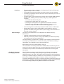
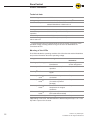
User manual
Interroll
ZoneControl
Chapter-ID: User manual
Chapter-ID: Version
Chapter-ID: Translation of the original instructions
Version 1.0 (12/2010) en
Translation of the original instructions
Manufacturer's address
Interroll Engineering GmbH
Hoeferhof 16
D-42929 Wermelskirchen
Tel. +49 2193 23 0
Fax. +49 2190 2022
www.interroll.com
Copyright
The copyright of this manual remains with Interroll Engineering GmbH. The
operating instructions contain technical regulations and drawings which may not
be reproduced partially or in full, transmitted by any means, utilized without
permission for competitive purposes or disclosed to third parties.
Version 1.0 (12/2010) en
Translation of the original instructions
ZoneControl
Table of contents
Introduction
Information about the operating instructions . . . . . . . . . . . . . . . . . . . . . . . . 3
Warnings in this manual . . . . . . . . . . . . . . . . . . . . . . . . . . . . . . . . . . . . . . . 3
Further symbols . . . . . . . . . . . . . . . . . . . . . . . . . . . . . . . . . . . . . . . . . . . . . 4
Safety
General safety instructions .
Intended use . . . . . . . . . . .
Unintended use . . . . . . . . .
Qualified persons . . . . . . . .
Dangers . . . . . . . . . . . . . . .
Interfaces to other devices .
Operating modes . . . . . . . .
.
.
.
.
.
.
.
.
.
.
.
.
.
.
.
.
.
.
.
.
.
.
.
.
.
.
.
.
.
.
.
.
.
.
.
.
.
.
.
.
.
.
.
.
.
.
.
.
.
.
.
.
.
.
.
.
....
....
....
....
....
....
....
...
...
...
...
...
...
...
....
....
....
....
....
....
....
...
...
...
...
...
...
...
....
....
....
....
....
....
....
...
...
...
...
...
...
...
....
....
....
....
....
....
....
...
...
...
...
...
...
...
5
5
5
6
7
7
7
Product information
Product description .
Components. . . . . . .
Scope of delivery . . .
Label . . . . . . . . . . . .
Technical data . . . . .
Meaning of the LEDs
DIP switches . . . . . .
Meaning of signals . .
Dimensions . . . . . . .
.
.
.
.
.
.
.
.
.
.
.
.
.
.
.
.
.
.
.
.
.
.
.
.
.
.
.
...
...
...
...
...
...
...
...
...
....
....
....
....
....
....
....
....
....
...
...
...
...
...
...
...
...
...
............................ 8
. . . . . . . . . . . . . . . . . . . . . . . . . . . 11
. . . . . . . . . . . . . . . . . . . . . . . . . . . 11
. . . . . . . . . . . . . . . . . . . . . . . . . . . 11
. . . . . . . . . . . . . . . . . . . . . . . . . . . 12
. . . . . . . . . . . . . . . . . . . . . . . . . . . 12
. . . . . . . . . . . . . . . . . . . . . . . . . . . 13
. . . . . . . . . . . . . . . . . . . . . . . . . . . 14
. . . . . . . . . . . . . . . . . . . . . . . . . . . 14
Transport and storage
Ambient conditions for transport and storage . . . . . . . . . . . . . . . . . . . . . . 15
Transport . . . . . . . . . . . . . . . . . . . . . . . . . . . . . . . . . . . . . . . . . . . . . . . . . 15
Storage . . . . . . . . . . . . . . . . . . . . . . . . . . . . . . . . . . . . . . . . . . . . . . . . . . 15
Assembly
Warning notices concerning assembly . . . . . . . . . . . . . . . . . . . . . . . . . . .
Warning information relating to the electrical installation . . . . . . . . . . . . .
Installing the ZoneControl in a conveyor system . . . . . . . . . . . . . . . . . . .
Electrical installation . . . . . . . . . . . . . . . . . . . . . . . . . . . . . . . . . . . . . . . .
Sensors . . . . . . . . . . . . . . . . . . . . . . . . . . . . . . . . . . . . . . . . . . . . . . . . . .
Inputs and outputs . . . . . . . . . . . . . . . . . . . . . . . . . . . . . . . . . . . . . . . . . .
Wiring diagrams . . . . . . . . . . . . . . . . . . . . . . . . . . . . . . . . . . . . . . . . . . . .
16
16
17
17
19
20
22
Initial startup and operation
Commissioning . . . . . . . . . . . . . . . . . . . . . . . . . . . . . . . . . . .
Operation . . . . . . . . . . . . . . . . . . . . . . . . . . . . . . . . . . . . . . . .
Speed setting . . . . . . . . . . . . . . . . . . . . . . . . . . . . . . . . . . . . .
External influence on zero pressure accumulation conveying .
Complete clearing of a conveyor . . . . . . . . . . . . . . . . . . . . . .
...
...
...
...
...
....
....
....
....
....
..
..
..
..
..
26
26
27
27
29
Maintenance and cleaning
Warnings concerning maintenance and cleaning . . . . . . . . . . . . . . . . . . . 30
Maintenance . . . . . . . . . . . . . . . . . . . . . . . . . . . . . . . . . . . . . . . . . . . . . . 30
Cleaning . . . . . . . . . . . . . . . . . . . . . . . . . . . . . . . . . . . . . . . . . . . . . . . . . 30
Troubleshooting
Troubleshooting . . . . . . . . . . . . . . . . . . . . . . . . . . . . . . . . . . . . . . . . . . . . 31
Deviations in the conveying process . . . . . . . . . . . . . . . . . . . . . . . . . . . . 32
Abandonment and disposal
Abandonment. . . . . . . . . . . . . . . . . . . . . . . . . . . . . . . . . . . . . . . . . . . . . . 33
Disposal . . . . . . . . . . . . . . . . . . . . . . . . . . . . . . . . . . . . . . . . . . . . . . . . . . 33
Version 1.0 (12/2010) en
Translation of the original instructions
1
ZoneControl
Table of contents
Appendix
Electrical data of connectors . . . . . . . . . . . . . . . . . . . . . . . . . . . . . . . . . . . 34
Installation Declaration . . . . . . . . . . . . . . . . . . . . . . . . . . . . . . . . . . . . . . . 37
2
Version 1.0 (12/2010) en
Translation of the original instructions
ZoneControl
Introduction
Information about the operating instructions
Contents
Validity of the manual
This manual contains important advice, notes and information about the
ZoneControl in all phases of its lifecycle:
• Transport, assembly and start-up
• Safe operation, maintenance and troubleshooting, disposal
• Accessories
The manual describes the ZoneControl as it is delivered by Interroll.
In addition to this manual, special contractual agreements and technical
documents apply to special versions.
The manual is part of the
product
¾ For trouble-free, safe operation and warranty claims, read the manual and
follow the instructions before handling the ZoneControl.
¾ Keep the manual near to the ZoneControl.
¾ Pass the manual on to any subsequent operator or occupant of the
ZoneControl.
¾ Interroll does not accept any liability for malfunctions or defects due to nonobservance of this manual.
¾ If you have any questions after reading the operation manual, feel free to
contact our customer service. See the last page for your local contact.
Warnings in this manual
The warnings in this document refer to risks which may arise while using the
ZoneControl. For relevant warnings, see "Safety", page 5 and the warnings at the
beginning of each chapter.
There are three categories of danger. The following signal words are used in the
document as required:
• Danger
• Warning
• Caution
Signal word
Meaning
Danger
Indicates a hazardous situation which, if not
avoided, will result in death or serious injury.
Warning
Indicates a hazardous situation which, if not
avoided, could result in death or serious injury.
Caution
Indicates a hazardous situation which, if not
avoided, may result in minor or moderate injury.
Structure of warnings
DANGER
Nature and source of the hazard
Possible consequence of non-observance
¾ Information about how to avoid the hazard.
Version 1.0 (12/2010) en
Translation of the original instructions
3
ZoneControl
Introduction
Further symbols
This symbol identifies possible material damage.
¾ Information about how to avoid damage.
Important
This symbol displays safety instructions.
Hint
This symbol marks useful and important information.
¾ This symbol marks the steps that have to be carried out.
4
Version 1.0 (12/2010) en
Translation of the original instructions
ZoneControl
Safety
General safety instructions
The ZoneControl is designed according to the technical state of the art and is
reliable in operation, once distributed. However, risks may still arise.
• Risks of physical injury to the user or bystanders.
• Adverse effects of the ZoneControl and other material.
Important
Disregarding the warnings in this manual may lead to serious injury.
¾ Always read the entire operating and safety instructions before starting to
work with the ZoneControl and follow the information contained herein in full.
¾ Only instructed and qualified persons may work with the ZoneControl.
¾ Always keep this user manual at hand when working on the ZoneControl so
that you can consult it quickly if required.
¾ Always comply with relevant national safety regulations.
¾ If you have any questions after reading this user manual, feel free to contact
our customer service. See the last page for contact information.
Intended use
The ZoneControl should only be used for industrial applications and in an
industrial environment to control one of the following RollerDrives:
• RollerDrive EC310
• RollerDrive EC300 (with adapter cable)
It must be integrated into a conveyor module or conveyor system. Any other use
is not permitted and is deemed to be improper.
Any modifications that affect the safety of the product are not permitted.
The ZoneControl may only be operated within the defined operating limits.
The ZoneControl must be supplied by a regulated power supply unit with a
nominal DC voltage of 24 V (minimum 19 V, maximum 26 V).
Unintended use
Applications not according to the intended use of the ZoneControl require
approval from Interroll.
Version 1.0 (12/2010) en
Translation of the original instructions
5
ZoneControl
Safety
Qualified persons
Qualified persons are persons who read and understand the manual and, taking
national regulations into account, can competently execute incidental work.
Only instructed and qualified persons may work with the ZoneControl, taking the
following into account:
• the relevant manuals and diagrams,
• the warning and safety instructions in this manual,
• the system specific regulations and requirements,
• national or local regulations and requirements for safety and accident
prevention.
6
Version 1.0 (12/2010) en
Translation of the original instructions
ZoneControl
Safety
Dangers
Important
The following list informs you about the various types of danger or damage that
may occur while working with the ZoneControl.
Persons
Electricity
¾ Maintenance or repair work must only be executed by authorized and qualified
persons in accordance with the applicable regulations.
¾ Before using the ZoneControl, ensure that no unauthorized persons are near
the conveyor.
¾ Only operate the ZoneControl with control voltage complying with the
requirements of EN 60401-1, PELV.
¾ Only perform installation and maintenance work after you have switched off
the power.
¾ Ensure that the power cannot be turned on accidentally.
Working environment
¾ Do not use the ZoneControl in explosive environments.
¾ Always remove materials and objects which are not required from the work
area.
Malfunctioning during
operation
¾ Regularly check the ZoneControl for visible damage.
¾ In case of fumes, turn off the power at once and ensure that it cannot be
turned on accidentally.
¾ Contact qualified personnel immediately to find the source the malfunction.
Maintenance
¾ As the product is maintenance free, you only need to check the ZoneControl
regularly for visible damage and that all leads and screws are still tightened.
Interfaces to other devices
By assembling the ZoneControl in a conveyor module, further hazards may
occur. These hazards are not part of this manual and have to be analyzed during
the design, installation and startup of the conveyor module.
¾ After assembling the ZoneControl in a conveyor module, check the whole
system for a new potential dangerous spot before switching on the conveyor.
Operating modes
Normal mode
Operation of the installed device at the end customer's as a component in a
conveyor in a complete system.
Special mode
All operating modes which are required to guarantee and maintain safe and
normal operation.
Special operating mode
Explanation
Comment
Transport/Storage
Loading and unloading, transport and storage
-
Assembly/Initial start-up
Installation at the end customer's and
performing the test run
When de-energized
Cleaning
External cleaning
When de-energized
Maintenance/Repairs
Maintenance and inspection tasks
When de-energized
Troubleshooting
Troubleshooting in the event of a fault
When de-energized
Fault elimination
Eliminating the fault
When de-energized
Shut-down
Dismantling from the conveyor
When de-energized
Disposal
Disposal of ZoneControl and packaging
-
Version 1.0 (12/2010) en
Translation of the original instructions
7
ZoneControl
Product information
Product description
The ZoneControl is used to facilitate zero pressure accumulation conveying,
meaning that goods are transported without coming into contact with each other.
To achieve this, the conveyor is sub-divided into zones. One zone consists of a
RollerDrive, several idler rollers, a ZoneControl and corresponding sensors.
Zero pressure accumulation conveying is achieved by there being only one
product in every zone and by the zones retaining the package until the
downstream zone is detected as being "free" by the corresponding sensor. When
accumulation occurs, a signal is transmitted upstream to retain the next package.
A gap is always left between the goods being transported so that no
accumulation pressure occurs.
Schematic diagram: three zones controlled by ZoneControl
1
2
3
4
5
Zone 1
Zone 2
Zone 3
Direction of travel
ZoneControl
6
7
8
9
bl
Zone sensor
RollerDrive
Power supply
Peer-to-peer connection
Package
The sensor in zone 1 has detected a package. The ZoneControl in zone 1 sends
a request to zone 2 to ask whether the package can continue to be conveyed.
Since zone 2 also contains a package, its ZoneControl denies permission until
this package has been transferred to zone 3 (singulated release mode) or at the
very least its onward transport has been started.
In singulated release mode, the package is only conveyed on if the package in
the downstream zone has fully left this zone. In train release mode, the packages
are virtually transported simultaneously (with a time delay of approx. 125 ms to
reduce peak current when starting up.)
The ZoneControl in zone 1 only activates the RollerDrive in this zone after it
receives the corresponding signal from the ZoneControl in zone 2.
8
Version 1.0 (12/2010) en
Translation of the original instructions
ZoneControl
Product information
Functions
•
•
•
•
•
•
Speed settings
The speed and direction of rotation of a RollerDrive EC310 (or EC300 with
adapter cable) can be controlled.
The signals from two sensors (start and zone sensors) can be evaluated.
The feeding of packages into the start zone can be controlled by a sensor or
by an external signal.
Transport logic can be influenced by external control signals (ZONE_START,
ZONE_STOP, ZONE_STATUS, CLEAR, DIR_RET), enabling different
functions:
– Automatic stop at personal gates
– Individual zone stops within the conveyor line
– Clearing the entire system in or against the set direction of rotation
– Feed-in/removal of packages outside of the start and end zone (for
instance in conjunction with an external handling system)
The control signals can either be processed in PNP mode or in NPN mode.
Regenerative braking: When the RollerDrive motor brakes, it acts as a
generator and feeds energy back into the power supply. The DriveControl is
fitted with a brake chopper.
The speed of the RollerDrive can be adjusted in two different ways by
ZoneControl:
• Internally at eight levels by means of three DIP switches
• Externally continuously via the analog input SPEED (is handled with priority
and enables more fine-tuned adjustment)
The speed setting is converted to an analog control voltage by the ZoneControl
and output by the RollerDrive as a reference setting. This reference setting is
independent of the RollerDrive gears and their diameter.
Speed setting of the see "Speed setting", page 27.
The acceleration and braking behaviour of the RollerDrive is defined by its own
moment of inertia, the gears used, the conveying speed, the moment of inertia of
connected conveyor rollers, the selected torque transmission and the goods
transported.
Feedback of energy /
Overvoltage protection
Version 1.0 (12/2010) en
Translation of the original instructions
If the RollerDrive is stopped by the ZoneControl or if the speed is reduced
abruptly, the kinetic energy of the package is regeneratively converted into
electrical energy in the motor. This energy is then fed back into the ZoneControl,
resulting in increased voltage in the DC-net. This is limited to a non-critical level
(28 V) by the integral brake chopper. However, if there are enough other
consumers attached to the DC-net, the voltage rise will be low and the energy will
be fed back in, resulting in the energy being available to other consumers in the
DC-net and energy-savings being made if conditions are favourable.
9
ZoneControl
Product information
Temperature protection
If operational conditions mean that the brake chopper is switched on so often that
the upper temperature limit of approx. 90 °C (measured internally) is reached,
then the ZoneControl switches off. If temperature protection is active, this is
shown on the LED display. When the ZoneControl has cooled down, the
RollerDrive restarts automatically when a signal is pending.
CAUTION
Unintended start-up of the RollerDrive following the
ZoneControl cooling down
Danger of crushing of limbs and damage to goods
¾ Ensure that no start signal is pending during the
cooling-down process.
Lock period for signal
modifications / Debouncing
The external signal inputs, the sensor connections and the DIP switches are
protected by the firmware to guarantee operation in the event of edge-unstable
and bouncing input-levels. This means that after a signal status change, there is
a time gap of 20 ms in which no additional status change is accepted. The
sample applies to the sensor inputs, where signal status changes are only
processed 50 ms after a signal modification.
P
1
t
0
tx
1
2
3
After-run time
Signal (with effect) and start of the lock time tx
Signals with no effect, as they lie within the lock time t x
The first signal that has an effect after the lock time tx
Once a package has left the sensor of a zone, then the RollerDrive in this zone
continues to run for additional 4 seconds. At the end of 4 seconds, the
RollerDrive stops, providing no new package is transferred from the upstream
zone.
This feature provides the following benefits:
• Energy-savings by switching off the RollerDrive if no further packages have to
be transported.
• Avoidance of unnecessary start/stop operation if there are no gaps between
the packages.
10
Version 1.0 (12/2010) en
Translation of the original instructions
ZoneControl
Product information
Components
ZoneControl
1
2
3
4
5
6
Upstream PTP connector 1)
Zone sensor connector
Start sensor connector
RollerDrive connector
Mounting link with hole for
countersunk screw
Power supply connector
7
8
9
bl
bm
1)
Inputs/outputs connectors
Downstream PTP connector
Cover for DIP switches
Marker (changeable)
Red and green LED
1)
PTP = Peer-to-Peer connection
Scope of delivery
The ZoneControl contains the following components:
• ZoneControl
• Mating plug for power supply (WAGO 734-102/xxx-xxx)
• Mating plug for inputs/outputs (WAGO 733-108/xxx-xxx)
• Spare tool for power supply mating plug (black)
• Spare tool for inputs/outputs mating plug (yellow)
Label
The information on the label is used to identify the ZoneControl.
ZoneControl
for RollerDrive
123456789
123456789
06/10
Interroll Enineering GmbH
42929 Wermelskirchen • Germany
www.interroll.com
ZoneControl
1
2
3
Version 1.0 (12/2010) en
Translation of the original instructions
Manufacturer
Product name
Week and year of production
4
5
6
Manufacturer's address
Article number
Serial number
11
ZoneControl
Product information
Technical data
Rated voltage
24 V DC
Voltage range
19 to 26 V DC (no polarity protection)1)
Current consumption
with RollerDrive: 3 to 5 A
without RollerDrive: 0.08 A to 0.5 A
Protection classification
IP20
Cooling
Convection
Ambient temperature in
operation
0 °C to 40 °C (32 °F to 104 °F)
Air humidity
5 to 95 %, condensation not permissible
Installation height
above sea level
max. 1,000 m (max. 3,300 ft)
1)
A single ZoneControl is protected against reverse polarity connection of the
operation voltage. Polarity protection is gone as soon as assemblies are
connected via PTP.
Meaning of the LEDs
The LEDs indicate the operating condition of the ZoneControl and the RollerDrive
and provide information about the operating voltage.
LED green
LED red
Meaning
Behaviour of
RollerDrive
2)
Flashing
Initialisation of
ZoneControl
Depending on
sensor assignment
Off
ZoneControl ready for
operation
Stop
Off
RollerDrive receives start
signal
Rotates
On steady
Flashes
once 2)
RollerDrive faulty or not
connected
Stop
On steady
Flashes
twice 2)
Fault in conveyor process
(for instance jammed
package)
Stop
On steady
Flashes three
times 2)
Shutdown due to excessive
temperature in chopper
resistance
Stop
Off
Flashes four
times 2)
System error (for instance
PTP cable disconnected)
Stop
Off
On steady
Fuse triggered
Stop
Flashing
On steady
Flashing
2)
2)
2)
Depending on the error, the LED flashes in different sequences (0.5 s on - 0.5 s
off) within a period of 4 seconds.
12
Version 1.0 (12/2010) en
Translation of the original instructions
ZoneControl
Product information
DIP switches
The DIP switches can be used to select the speed, direction of transportation,
operating mode and logic conversion (PNP/NPN). Factory default of the DIP
switches 1 to 3 is ON and that of DIP switches 4 to 8 is OFF.
DIP switches
ON
OFF
DIP SPEED
A, B, C
Speed setting (see "Speed setting", page 27)
DIP EPA/BA
Train release mode (BA)
DIP DIR
RollerDrive rotates in an anticlockwise direction 2)
1)
DIP PNP/NPN Signals are emitted in
accordance with NPN logic
1)
Singulated release (EPA)
1)
RollerDrive rotates in a
clockwise direction 2)
Signals are emitted in
accordance with PNP logic
see "Product description", page 8
2)
The direction of rotation is seen from the connecting cable side, if the external
input DIR_RET is not switched. Combined with a signal at the CLEAR signal
input, the direction of rotation is reversed if the DIR_RET input is switched.
DIP switches on the ZoneControl
1
2
3
4
5
6
Version 1.0 (12/2010) en
Translation of the original instructions
SPEED A
SPEED B
SPEED C
EPA/BA
DIR
PNP/NPN
13
ZoneControl
Product information
Meaning of signals
ZONE_STATUS
The ZONE_STATUS signal is the output signal of the handshake function of the
ZoneControl. The assigned signal input is ZONE_START.
The ZONE_STATUS signal is active when:
• The ZONE_START signal is active.
• The start or zone sensor is occupied (by regular in-feed of a package or by
placing a package on a previously empty zone).
The ZONE_STATUS signal gets in-active when:
• A package initially standing is conveyed into the following zone. When the
zone sensor becomes free, the ZONE_STATUS gets in-active providing no
further package is following.
• If a package does not reach the zone sensor, the system assumes after
5 seconds that the package has been manually removed and the
ZONE_STATUS signal gets in-active.
• If a standing package is removed manually (and the zone sensor gets thereby
freed), the RollerDrive continues rotating for 2 seconds. If the sensor is not
occupied again during this time and no other package follows, the
ZONE_STATUS signal gets in-active.
Dimensions
130
6
6.5
118
6.5
Ø6
42
55
108
2.5
24
ZoneControl
14
Version 1.0 (12/2010) en
Translation of the original instructions
ZoneControl
Transport and storage
Ambient conditions for transport and storage
Permissible ambient temperature
-20 °C to 70 °C (-4 °F to 158 °F)
Permissible relative humidity
5 to 95 %
Condensation not permissible.
Transport
•
Every ZoneControl is packaged in its own cardboard box.
CAUTION
There is a risk of injury if transported incorrectly
¾ Only qualified and authorized persons should transport
the product.
¾ Follow the instructions below.
¾
¾
¾
¾
Do not stack more than four cardboard boxes on top of each other.
Check that the ZoneControls are correctly fixed prior to transport.
Avoid serious impacts during transport.
Check every ZoneControl for visible damage and completeness (mating plugs
and spare tools) following transport (see "Scope of delivery", page 11).
¾ In the event of damage, take photos of the damaged parts.
¾ Report any damage caused by transport immediately to the transport
company and Interroll to retain the right to claim for compensation.
¾ Do not expose the ZoneControls to serious fluctuations in temperature as this
could lead to condensation.
Storage
CAUTION
Risk of injury due to improper storage
¾ Do not stack more than four cardboard boxes on top of
each other.
¾ Check each ZoneControl for damage after storage.
Version 1.0 (12/2010) en
Translation of the original instructions
15
ZoneControl
Assembly
Warning notices concerning assembly
Risk of damage leading to failure or shortened life
expectancy of the DriveControl
¾ Follow the instructions below.
¾ Do not drop or mishandle the ZoneControl to avoid internal damage.
¾ Check each ZoneControl visually for damage before assembly.
Warning information relating to the electrical installation
Risk of damage to the ZoneControl
¾ Observe the following safety information.
¾ Electrical work should only be performed by qualified and authorised persons.
¾ Disconnect the power supply before installing, removing or rewiring the
ZoneControl.
¾ Ensure that no hazardous voltage can come into contact with the connections
or the housing, not even in the event of a malfunction or fault.
¾ Do not connect AC current to the RollerDrive or the ZoneControl at any time,
as this will cause irreparable damage to the device.
¾ Do not use earth connections or earth wires as a protective conductor (PE).
¾ Do not apply too much tension or load to the motor connector. The cable
insulation can become damaged if the cable is bent at the plug and the
ZoneControl or the RollerDrive could fail.
¾ Only use cables that are dimensioned sufficiently for the application.
¾ Ensure that current load at each terminal or terminal block does not exceed
10 A.
¾ Ensure that the switching power supply unit supplying the DriveControl
supplies a nominal DC voltage of 24 V with a maximum deviation of ±8 %.
¾ Ensure that the RollerDrive, the ZoneControl and the voltage source are
connected to the conveyor frame or supporting structure in such a way that
they are properly earthed. Incorrect earthing can result in the build-up of static
charge, causing the motor or ZoneControl to malfunction or fail prematurely.
¾ Only use the specified mating plug (see "Inputs and outputs", page 20) and
the spare tool supplied.
¾ Ensure that the ZoneControl is not reverse connected. The ZoneControl will
be damaged beyond repair when power is applied if the ZoneControl is
reverse connected and there is a peer-to-peer connection.
¾ Only apply operating voltage when all of the cables have been connected.
16
Version 1.0 (12/2010) en
Translation of the original instructions
ZoneControl
Assembly
Installing the ZoneControl in a conveyor system
¾ Locate a flat surface for mounting the ZoneControl.
¾ Use the ZoneControl as a template and mark the centre of both mounting
holes. For the distance between the holes, see "Dimensions", page 14.
¾ Drill two ø 5.6 - 6 mm (0.22 - 0.24 in) mounting holes at the marked spots.
¾ Fasten the ZoneControl.
¾ Ensure that the housing is not distorted.
Electrical installation
Hint
The ZoneControl is fitted with an internal, non-replaceable fuse to protect the DCnet and all of the coupled users against a short circuit in the RollerDrive (or
generate current of more than 10 A). The user must protect all other lines.
The ZoneControl should be fixed to the side of the conveyor on which the
RollerDrive cable is located. All of the connections should be routed to one side
of the conveyor to simplify cabling.
The cabling of the PTP connection must always following the direction of the
conveyor, that is to say that the PTP downstream connection of the upstream
zone must be connected to the PTP upstream connection of the downstream
zone etc. This also applies if one/several ZoneControl(s) have to be fitted on the
other side of the conveyor.
1
2
3
Version 1.0 (12/2010) en
Translation of the original instructions
Direction of travel
ZoneControl
RollerDrive
4
5
6
Power supply
Peer-to-peer connection
Package
17
ZoneControl
Assembly
Required cables
Connection
Conductor cross-section / Information
Inputs/
Outputs
fine-strand: 0.08 to 0.5 mm2
fine-strand with end-splice: 0.25 to 0.34 mm2
AWG: 28 to 20
Stripped length: 5 to 6 mm
Power supply
fine-strand, H05(07) V-K: 1.5 mm 2
(optionally with end-splice according to DIN 46228/1)
AWG: 16
Stripped length: 6 to 7 mm
Peer-to-peer
connection
Commercially-available Cat-5 cable (network or Ethernet
cable)
¾ Strip the strand ends as per the contact manufacturer's recommendations and
possibly fit end sleeves.
¾ Insert the input/output and sensor wires into the mating plug using the yellow
tool (see "Inputs and outputs", page 20).
¾ Insert the power supply wires into the mating plug with the black spare tool.
¾ Insert the mating plug into the ZoneControl.
¾ Ensure that all of the ZoneControl are connected to a common ground.
¾ Adjust the SPEED A, SPEED B, SPEED C, EPA/BA and DIR DIP switches
according to requirements (see "Operation", page 26).
¾ Adjust the PNP/NPN DIP switch according to the signal level being used
(applies to sensors and inputs and outputs).
¾ Insert the plug of the RollerDrive so that the "RD" labelling of the ZoneControl
can be read and the "EC310" labelling is to the rear, i.e. cannot be read.
¾ Insert the plug of the PTP connection. When the ZoneControl is in the start
zone and end zone, one PTP connection remains free. There is no need for
an end resistor.
Signal status of inputs
PNP/NPN
Status
ZONE_STOP
ZONE_START
CLEAR
DIR_RET
START/
ZONE_SENS_IN
PNP
DIP = OFF
active
+24 V
+24 V
+24 V
+24 V
+24 V
in-active
–
–
–
–
–
NPN
DIP = ON
active
GND
GND
GND
GND
GND
in-active
–
–
–
–
–
Signal status of outputs
PNP/NPN
Status
ZONE_STATUS
ERROR
EXT_ON
PNP
DIP = OFF
active
+24 V
+24 V
+24 V
in-active
–
–
–
NPN
DIP = ON
active
GND
GND
GND
in-active
–
–
–
18
Version 1.0 (12/2010) en
Translation of the original instructions
ZoneControl
Assembly
Schematics of all outputs
UB
UB
Rs
ZoneControl
ZoneControl
Rs
GND
GND
With PNP logic
With NPN logic
UB = Operating voltage
Rs = Internal overload protection
GND = Ground
Sensors
The following types of sensors can be connected (the sensor must be active if the
package is in the detection area):
• Light scanner light-switching
• Light barrier dark-switching
Type of
sensor
PNP
Light barrier
(with
reflector)
Light- or
darkswitching
Opener/
Closer
Darkswitching
Closer,
normally
open
Logical
output
Light beam
Switch
symbol
Package
detected
No
Not
interrupted
Electrical output
Switched
on
Voltage
No
–
Yes
24 V
No
–
Yes
24 V
+24 V
Yes
Interrupted
No
Interrupted
Yes
Not
interrupted
+24 V
Light scanner
NPN
Light barrier
(with
reflector)
Reflective
light scanner
Lightswitching
Darkswitching
Lightswitching
Version 1.0 (12/2010) en
Translation of the original instructions
Closer,
normally
open
Closer,
normally
open
Closer,
normally
open
+24 V
+24 V
No
Not
interrupted
No
–
Yes
Interrupted
Yes
0V
No
Interrupted
No
–
Yes
Not
interrupted
Yes
0V
19
ZoneControl
Assembly
Inputs and outputs
RollerDrive connection: 8 mm snap-in, 5-pin, pin location in accordance
with DIN EN 61076-2
1
2
3
+24 V DC
Output for direction of rotation
Ground
4
5
Fault input
Speed output
Start sensor connector: WAGO 733-103 mating plug
WAGO 733-363/105-604
1
2
+24 V DC
START_SENS_IN (input for start
sensor signal)
3
Ground
Zone sensor connector: WAGO 733-103 mating plug
WAGO 733-363/105-604
1
2
20
+24 V DC
ZONE_SENS_IN (input for zone
sensor signal)
3
Ground
Version 1.0 (12/2010) en
Translation of the original instructions
ZoneControl
Assembly
Upstream peer-to-peer connection: RJ45 socket, 8-pin Molex 43860
Mating plug: pre-manufactured patch cable
Power supply connector: WAGO 734-102 mating plug
WAGO 734-162/105-604
1
GND (Ground)
2
+24 V DC
Inputs/outputs connector: WAGO 733-108 mating plug
WAGO 733-368/105-604
1
2
3
4
Version 1.0 (12/2010) en
Translation of the original instructions
EXT_ON (Output for additional
start signal)
CLEAR (Input for clear signal)
SPEED (Input for speed setting)
DIR_RET (Input for change of
transport direction and only
effective when there is an active
signal at CLEAR).
5
6
7
8
ERROR (Output for error signal)
ZONE_STATUS (Output for zone
status signal)
ZONE_START (Input for start
signal)
ZONE_STOP (Input for stop signal)
21
ZoneControl
Assembly
Downstream peer-to-peer connector: RJ45 socket, 8-pin Molex 43860
Mating plug: pre-manufactured patch cable
Hint
The electrical data for each connection is specified in the appendix (see
"Electrical data of connectors", page 34).
Wiring diagrams
Abbreviations used
+24 V
GND
PTP
Operating voltage
Ground (earth)
Peer-to-peer connection
ROLLER
DRIVE
ZoneControl within the
conveyor section
PTP
1
GND +24V
PTP
Zone sensor
This ZoneControl can be located at any position between the start and end zone.
This switch enables zero pressure accumulation conveying without additional
functions.
The ZoneControl is connected to the adjacent ZoneControls via the Peer-to-Peer
cable. The zone sensor is fed with operating voltage via the sensor connector.
22
Version 1.0 (12/2010) en
Translation of the original instructions
ZoneControl
Assembly
ROLLER
DRIVE
ZoneControl at the start of the
conveyor section
GND +24 V
PTP
GND (NPN)
+24 V (PNP)
1
2
3
Start sensor
Zone sensor
Switch A: External signal at the ZONE_START input
Handshake to the upstream conveyor section: Der Zonenstatus (belegt oder frei)
kann über das Signal ZONE_STATUS abgefragt werden (see "ZONE_STATUS",
page 14). The first zone of the ZoneControl conveyor can be started in the
following ways:
•
•
Start sensor (button A is not needed)
External signal at the ZONE_START input (symbolised by switch A; start
sensor not needed)
The function of the switch can be provided using any switching element (e. g.
PLC). The signal can be switched in NPN or PNP mode.
Version 1.0 (12/2010) en
Translation of the original instructions
23
ZoneControl
Assembly
GND +24 V
ROLLER
DRIVE
ZoneControl at the end of the
conveyor section
PTP
GND (NPN)
+24 V (PNP)
1
2
Zone sensor
Button: External signal at the ZONE_START input
When the package has reached the sensor in the last zone it is stopped by
default. An external signal must be given at the ZONE_START input of the last
zone to discharge. This can be a switch (refer to the example in the diagram
above) or an external control (PLC). The signal can be switched in NPN or PNP
mode. The status of the last zone is given by the ZONE_STATUS output. If there
is no package in the relevant zone sensor's detection range and the
ZONE_START signal is active, the RollerDrive does not rotate.
Depending on signal length and discharge mode (single or train release) either
one or more packages will be released.
Connection of the external
speed control
+24 V
GND
+
1
2
3
-
ZoneControl
RollerDrive
Peer-to-peer connection
4
5
SPEED input (Pin 3)
External speed setting (e.g. by
potentiometer)
An external SPEED signal can be connected to control the speed of the whole
conveyor externally. The signal should only be connected to one ZoneControl, as
it is transmitted via the PTP connection to all other ZoneControl. The position of
the ZoneControl within the conveyor and the cable length of the PTP connection
is immaterial.
The voltage range for the SPEED signal is between 0 and 10 V DC with a
maximum current of 2 mA. DC voltage must be kept stable to maintain a constant
conveyor speed.
24
Version 1.0 (12/2010) en
Translation of the original instructions
ZoneControl
Assembly
Connection of a second
RollerDrive
There is an option with a conveyor to drive zones with other RollerDrive that are
switched on and off synchronously to the RollerDrive of the ZoneControl. This
can, for instance be necessary with heavy packages or long zones.
ROLLER
DRIVE
¾ Connect the EXT_ON output of the ZoneControl to the SPEED A input of a
DriveControl 20.
1
DriveControl
ROLLER
DRIVE
7
GND +24V
+24V GND
ZoneControl
8
PTP
PTP
¾ Connect the ground wire of the ZoneControl (GND) to the signal ground
Common GND of the DriveControl 20. If possible, use the same power supply
for the ZoneControl and DriveControl 20.
¾ Preselect a speed that is comparable to that of the ZoneControl on the
DriveControl 20 using DIP switches SPEED A to D.
¾ If the function DIR_RET is to be used in the application, connect the DIR input
of the DriveControl 20 to the DIR_RET signal of the ZoneControl and on the
DriveControl 20 set the DIP switch DIR in such a way that the RollerDrive is
rotating in the correct direction.
Hint
Changes to the speed via an external SPEED signal only affect RollerDrive that
are connected directly to a ZoneControl. The RollerDrive that is connected to a
DriveControl 20 do not experience any change of speed from the signal.
Version 1.0 (12/2010) en
Translation of the original instructions
25
ZoneControl
Initial startup and operation
Commissioning
Pre-commissioning checks
¾ Ensure that the ZoneControl has been correctly fastened to the profile and
that all screws have been correctly tightened.
¾ Ensure that there are no additional areas of danger caused by interfaces to
other components.
¾ Ensure that the wiring is in accordance with the specification and legal
directives.
¾ Check all protection devices.
¾ Ensure that no personnel stand in hazardous areas near the conveyor.
Pre-commissioning checks
¾
¾
¾
¾
¾
¾
Check the ZoneControl for visible damage.
Check the DIP switch settings (see "DIP switches", page 13).
Check all protection devices.
Clearly specify and monitor the way goods are placed on the conveyor.
Ensure that the RollerDrive is not blocked.
Ensure that no personnel stand in hazardous areas near the conveyor.
Operation
CAUTION
Accidental start-up of the RollerDrive
Danger of crushing of limbs and damage to goods
¾ Ensure that no unauthorised persons are near the
conveyor before switching on the operating voltage.
Hint
Ambient conditions during operation see "Technical data", page 12
The ZoneControl is initialised after the operating voltage has been applied. The
ZoneControl is then brought into a defined basic state and packages that are not
within the detection range of a sensor are transported onto the next zone sensor.
The RollerDrives in unoccupied zones rotate and RollerDrives in occupied zones
do not rotate. The start and end zones are automatically detected if they are
wired correctly. Initialisation mode takes 4 seconds. During the initialisation mode
the zone sensor can be assigned as often as required.
26
Version 1.0 (12/2010) en
Translation of the original instructions
ZoneControl
Initial startup and operation
Speed setting
Internal speed setting on the
ZoneControl
Requirement: The external SPEED input is not connected or in-active.
¾ Set the required speed using the DIP switches (see table).
Hint
It is not possible to stop the RollerDrive by connecting ground to the external
SPEED input.
Setting of the SPEED DIP
switches on the ZoneControl
Speed at gear ratio
A
B
C
4:1
9:1
12:1
16:1
24:1
36:1
48:1
64:1
96:1
on
on
on
3.93
1.75
1.31
0.98
0.65
0.44
0.33
0.25
0.16
on
on
off
3.39
1.51
1.13
0.85
0.57
0.38
0.28
0.21
0.14
m/s
on
off
on
2.86
1.27
0.95
0.72
0.48
0.32
0.24
0.18
0.12
on
off
off
2.33
1.03
0.78
0.58
0.39
0.26
0.19
0.15
0.10
off
on
on
1.80
0.80
0.60
0.45
0.30
0.20
0.15
0.11
0.07
off
on
off
1.26
0.56
0.42
0.32
0.21
0.14
0.11
0.08
0.05
off
off
on
0.73
0.32
0.24
0.18
0.12
0.08
0.06
0.05
0.03
off
off
off
0.20
0.09
0.07
0.05
0.03
0.02
0.02
0.01
0.01
Speed setting via external
analog signal
Above a voltage of > 1 V, the SPEED signal has higher priority than the speed
setting by the internal DIP switches. The speed of the RollerDrive is controlled by
the external signal, irrespective of the position of the DIP switches.
¾ Set the speed of the RollerDrives by changing the external signal within a
range of 1 to 10 V. Changes to the signal will only be applied if they differ by
at least 0.1 V from the previous value.
¾ Set the external signal to 0 V to enable the internal speed setting by the DIP
switch.
Hint
The specified analog speed applies to all zones of the ZoneControl conveyor.
External influence on zero pressure accumulation conveying
The ZoneControl has two control signals to specifically influence the otherwise
automatic conveyor process.
•
•
ZONE_START
ZONE_STOPP
These signals enable the current conveyor logic of a zone to be interfered with to
the extent that locally generated START-STOP processes can be integrated
easily and simply into the parallel running global ZPA conveyor process.
CAUTION
Accidental start-up of the RollerDrive
Danger of crushing of limbs and damage to goods
¾ Before enabling the ZONE_START and ZONE_STOPP
signals, ensure that no unauthorised persons are in the
conveyor's hazard zones.
Version 1.0 (12/2010) en
Translation of the original instructions
27
ZoneControl
Initial startup and operation
ZONE_STOPP
•
•
•
•
Can be used at every zone.
Package is conveyed to the zone sensor in the affected zone.
When in-active, immediate transition to normal ZPA conveyor operation.
The signal does not stop the RollerDrive immediately.
ZONE_START
The ZONE_START signal is the input signal of the handshake function of the
ZoneControl. The associated signal output is ZONE_STATUS (see
"ZONE_STATUS", page 14).
•
Connected to the first zone of the conveyor:
– The start signal leads to the RollerDrive in the first zone starting, providing
that the zone sensor is not occupied.
– If the zone sensor is occupied, the RollerDrive will not be started.
– If the signal is active while a package is conveyed into the first zone, the
RollerDrive will continue running until the package reaches the sensor
(resulting in no Time-Out).
– If the ZONE_START remains active after the package has left the first
zone, the RollerDrive in the first zone will continue runing without a timeout.
•
Connected to a middle zone:
– The RollerDrive in the zone starts running immediately and under
compulsion disregarding any ZPA- or sensor status. (Caution: Risk of
collision). If the signal gets inactive, the zone again follows the rules of
zero pressure accumulation conveying. No initialisation takes place.
•
Connected to the last zone:
– If the last zone is occupied by a package, it is conveyed out of this zone. If
no further package follows, the RollerDrive stops after 4 seconds (run-on).
– If a further package is following, then it is also conveyed out of the zone
(depending on the type of discharge set) providing ZONE_START
continues to be active.
– If the signal is only given as a pulse, a package is conveyed out of the
zone, a further package would be conveyed to the zone sensor and stop
there.
– If the start signal is given and the last zone is not occupied, the RollerDrive
does not run.
– If the signal remains active and a package is conveyed to the last zone, the
RollerDrive does not stop but the package is transported directly out of the
zone.
Hint
The ZONE_START and ZONE_STOPP signals should be given as pulses to
guarantee functional assignment to the ZPA conveyor process. The duration of
the pulse should be shorter than the time the longest package takes to go
through the shortest zone.
28
Version 1.0 (12/2010) en
Translation of the original instructions
ZoneControl
Initial startup and operation
Complete clearing of a conveyor
A conveyor can be completely cleared by the CLEAR signal if required.
¾ Activate the CLEAR signal in the first or last zone of the conveyor.
The CLEAR signal is transmitted via the PTP cable to all other zones. It
immediately overrides the running conveyor logic and it must kept active as long
as the clearing of the conveyor takes. It causes forced conveyance: All
RollerDrive rotate simultaneously at the respectively preset speed and in the
preset direction without taking the zone sensors into consideration.
Any CLEAR signal connected to an intermediate zone is ineffective. CLEAR
cannot be active while the ERROR signal is activated.
As soon as the CLEAR signal is inactive again, the conveyor goes through an
initialisation cycle.
If the DIR_RET signal is active parallel to the CLEAR signal, all of the connected
RollerDrive rotate in the opposite direction than set by the DIP switch. DIR_RET
and CLEAR must be connected to the same ZoneControl. The DIR_RET signal is
only effective during CLEAR.
Version 1.0 (12/2010) en
Translation of the original instructions
29
ZoneControl
Maintenance and cleaning
Warnings concerning maintenance and cleaning
CAUTION
Risk of injury due to improper handling or accidental
motor starts
¾ Maintenance work and cleaning may only be executed
by qualified and authorized persons.
¾ Only perform maintenance work after switching off the
power. Ensure that the ZoneControl cannot be turned
on accidentally.
¾ Set up signs indicating maintenance work.
Maintenance
Inspecting the ZoneControl
The ZoneControl itself is maintenance-free. For avoidance of faults however,
regular inspection of the connections and fixings is required.
¾ As part of the regular control and maintenance work on the conveyor, ensure
that the screws of the ZoneControl are still tight and that the cables are still
laid properly and connected to the terminals.
Replacing the ZoneControl
If a ZoneControl is damaged, it has to be replaced.
¾ Install a new ZoneControl (see "Abandonment", page 33 and see "Installing
the ZoneControl in a conveyor system", page 17).
Cleaning
Dust and dirt in combination with humidity may bridge the electric circuit.
Therefore, in a dirty environment, periodic cleaning will help to avoid shortcircuits which could damage the ZoneControl.
CAUTION
Risk of damage to the ZoneControl due to incorrect
cleaning
¾ Do not immerse the ZoneControl in liquids.
¾ Do not use cleaning agents.
¾ Clean away dust and soiling if necessary.
¾ For more thorough cleaning, disconnect the ZoneControl from the power
supply, remove (see "Abandonment", page 33), and wipe over with a damp
cloth.
30
Version 1.0 (12/2010) en
Translation of the original instructions
ZoneControl
Troubleshooting
Troubleshooting
Symptom
Possible cause
Help
ZoneControl is not working or is
working incorrectly
No power supply
¾ Check whether the output voltage of
the power supply is within the
specified voltage range.
¾ Check the connections and correct if
necessary.
Wrong position of the DIP switches
¾ Check and if necessary correct the
position of the DIP switches (see
"DIP switches", page 13).
ZoneControl faulty or damaged
Internal fuse triggered or faulty.
¾ Replace the ZoneControl.
RollerDrive is not working
RollerDrive is faulty or no power
supply
¾ Check whether the output voltage of
the power supply is within the
specified voltage range.
¾ Check the connections and correct if
necessary.
The ERROR signal is automatically
reset after elimination of the fault and
the ZoneControl immediately performs a
local reinitialisation of the affected zone.
Conveyor process interrupted
Packages jammed
¾ Remove jammed packages.
The ERROR signal is automatically
reset after elimination of the fault and
the ZoneControl immediately performs a
local reinitialisation of the affected zone.
Overheating of chopper resistor to >
90 °C
¾ Allow to cool down.
The ERROR signal is automatically
reset after cooling and the ZoneControl
continues the conveyor process.
PTP cable disconnection
¾ Check all of the PTP cable
connections.
PTP cable disconnection
¾ Switch operating voltage off and on
to reinitialise the conveyor system.
System error
The error signal is active in the event of the following faults:
• RollerDrive fault
• RollerDrive not connected
• Fuse faulty
• Upper and lower levels of permitted operating voltage transgressed
• Operating voltage has reverse polarity
• Chopper resistor overheating
• System error
• Time-Out: zone sensor does not become free within 5 seconds
Version 1.0 (12/2010) en
Translation of the original instructions
31
ZoneControl
Troubleshooting
Deviations in the conveying process
Removing a package from the
detection area of the zone
sensor
Time-out when leaving the
zone sensor
The zone sensor is freed by manual intervention (withdrawal or removal of a
package that has already stopped) or by sliding back:
The ZoneControl detects this state and let the RollerDrive run for 2 seconds in
the zone in order to move the package back into the detection area of the zone
sensor. Within the 2 seconds there is no signal sent via the PTP link to the
upstream zone that the zone is free. This is to prevent an other package from
moving in the zone. If the sensor is not occupied by a package within 2 seconds,
a free signal is sent to the upstream zone (the ZONE_STATUS signal becomes
in-active).
A package does not leave the current detection zone of the zone sensor or does
not reach the target area of the downstream zone (e g. by temporary removal of
the package). This can be caused by a blockage on the conveyor track, for
instance by the package becoming snagged or a barrier on the conveyor track.
Once the RollerDrive has started, the occupied zone sensor must become free
after 5 seconds. If the sensor is still occupied at the end of this time period, the
RollerDrive stops. The ERROR output becomes active and the next ZoneControl
displays an error by means of the error LED. An assumption is made that the
package is blocking the conveyor.
The time period of 5 seconds can result in long packages not being able to be
conveyed at a slow speed.
The error can be reset by pushing the package manually into the detection area
of the zone sensor in the downstream zone. By doing this, a zone sensor that did
not become free, should no longer be occupied. After elimination of the fault, the
affected zone runs a local initialisation.
Time-out when reaching the
zone sensor
As soon as a package has left the detection area of a zone sensor, the package
has 5 seconds time to occupy the zone sensor in the subsequent zone. This
means that the RollerDrive in the following zone runs for at least 5 seconds,
providing its zone sensor is not previously occupied. At the end of the 5 seconds,
the ZoneControl assumes that the package has been removed and stops the
RollerDrive. No error is active.
A further package that is occupying the zone sensor in the upstream zone, is only
transported into this zone on expiry of the 5 seconds, as this zone only transmits
a free signal after 5 seconds.
32
Version 1.0 (12/2010) en
Translation of the original instructions
ZoneControl
Abandonment and disposal
Abandonment
CAUTION
Risk of injury due to improper handling
¾ Abandonment may only be executed by qualified and
authorized persons.
¾ Only abandon the ZoneControl after switching off the
power. Ensure that the ZoneControl cannot be turned
on accidentally.
¾ Disconnect all cables from the ZoneControl.
¾ Unscrew the screws attaching the ZoneControl to the conveyor frame.
¾ Extract the ZoneControl from the conveyor frame.
Disposal
The operator is responsible for the proper disposal of the ZoneControl. In doing
so, industry-specific and local provisions must be observed for the disposal of the
ZoneControl and its packaging.
Version 1.0 (12/2010) en
Translation of the original instructions
33
ZoneControl
Appendix
Electrical data of connectors
Inputs/outputs connectors
ZONE_START, ZONE_STOP, DIR_RET, CLEAR, START_SENS_IN and
ZONE_SENS_IN inputs
Properties
24 V logic, bounced, GND reference potential
Reverse polarity
protection
max. 30 V DC
Overvoltage protection
max. 30 V DC
permanent, absence of harmonic
waves
Logic level low
0 to 5 V DC
npn = active
Input current low
max. 3 mA
Logic level high
15 to 28 V DC
Input current high
max. 4.5 mA
Response time for
repeated signal change
min. 20 ms
pnp = active
Outputs ZONE_STATUS, ERROR, RD_EXT_ON
Properties
34
not short circuit-proof
Output current
50 to 100 mA
at an operating voltage of 30 V,
max. 500 ms
Logic level low
0 to 5.5 V DC
open collector,
@ 50 mA,
Reference GND
Logic level high
12.5 to 30 V DC
open collector,
@ 50 mA,
Reference GND
Version 1.0 (12/2010) en
Translation of the original instructions
ZoneControl
Appendix
RollerDrive connector
Power supply (pin 1, 3)
Nominal value
24 V DC
Voltage range
18 to 26 V DC
Residual ripple
max. 600 mVpp
Rated current
0 to 2.3 A
Peak current
max. 5 A
max. 250 ms > 2.3 A,
time-dependent current flow
triangular, duty factor 19 %
Return electric strength
max. 35 V DC
absence of harmonic waves
max. 500 ms; after 500 ms the
reserve voltage must be 30 V,
duty factor max. 27 %
Direction of rotation output (pin 2)
Properties
not electrically isolated, short circuit-proof, infeed of
external voltage not permitted
Overvoltage protection
max. 30 V DC
Clockwise direction of
rotation
max. 4 V
logical 0
Output current low
max. 1 mA
load resistance = 57 k
Anticlockwise direction
of rotation
min. 7 V
logical 1
Output current high
max. 0.2 mA
with short circuit
Input error (pin 4)
Version 1.0 (12/2010) en
Translation of the original instructions
Properties
not electrically isolated
Reverse polarity
protection
max. 30 V DC
Max. voltage
30 V DC
Logic level low
max. 8.5 V DC
Fault current low
1.5 mA
max. 5 mA
Logic level high
12 to 30 V DC
Fault current high
max. 0.01 mA
at 1.5 mA
logical 0 = inactive = no error
logical 1 = active = error
35
ZoneControl
Appendix
Speed output (pin 5)
36
Properties
not electrically isolated
Speed operating range
of motor control voltage
2.3 to 10 V DC
RollerDrive rotates
Stop range
0 to 2 V DC
RollerDrive does not rotate
Precision of motor
control voltage
5%
Motor control voltage between
2.3 and 10 V DC
at 21 °C
Motor control voltage
ripple
250 mVpp
50 Max. load of motor
control current
0.16 to 2 mA
Input resistance of RollerDrive:
66 k
Modification speed
4.5 to 5 V/ms
0 - 100 % motor control voltage
Version 1.0 (12/2010) en
Translation of the original instructions
ZoneControl
Appendix
Installation Declaration
in accordance with the EC Machinery Directive 2006/42/EC, Appendix II B
The manufacturer:
Interroll Engineering GmbH
Hoeferhof 16
D - 42929 Wermelskirchen
Germany
hereby declares with sole responsibility that the product range
•
ZoneControl
is not a ready-to-use machine as defined by the EC Machinery Directive
and, therefore, does not fully comply with the requirements of this
directive. The commissioning of these conveyor modules is not permitted
until conformity of the entire machine/system in which they are installed
has been declared in compliance with the EC Machinery Directive.
The health and safety requirements as stated in Appendix I have been applied.
The special technical documents as stated in Appendix VII B have been compiled
and will be sent to the responsible authority if necessary.
Person authorized to compile the technical documents: Georg Malina,
Interroll Engineering GmbH, Hoeferhof 16, D - 42929 Wermelskirchen
Applied EC directives:
• Machinery Directive 2006/42/EC
• EMC Directive 2004/108/EC
• RoHS Directive 2002/95/EC
Applied harmonized standards:
• EN ISO 12100 Parts 1 and 2 "Safety of machinery - Basic concepts, general
principles for design" - Part 1: "Basic terminology, methodology" Part 2: "Technical principles"
Wermelskirchen, 31st March 2010
Armin Lindholm
(Managing Director)
(This declaration can be obtained at www.interroll.com, if needed.)
Version 1.0 (12/2010) en
Translation of the original instructions
37
Central Europe
Middle East
Denmark
Germany
Israel
Interroll Nordic A/S
Hammerholmen 2-6
DK-2650 Hvidovre/Denmark
Tel. +45 36 88 33 33
Fax +45 36 88 33 72
[email protected]
Interroll Fördertechnik GmbH
Höferhof 16
D-42929 Wermelskirchen
Tel. +49 2193 23 0
Fax +49 2193 20 22
[email protected]
ComTrans-Tech Ltd.
P.O.B. 17433
Tel-Aviv 61174
Israel
Tel. +972 54 4 27 27 47
Fax +972 3 7 44 08 64
[email protected]
Northern Europe
Interroll Service
Tel. +45 36 88 33 88
Iceland
IBH ehf
Dugguvogur 10
104 Reykjavik
Iceland
Tel. +354 562 6858
Fax +354 562 6862
[email protected]
Finland
Tel. +358 9 54 94 94 00
Fax +358 9 54 94 94 16
[email protected]
Austria
Tel. +49 2193 23 187
Fax +49 2193 23 164
Belgium
Tel. +49 2193 23 131
Fax +49 2193 23 164
[email protected]
Luxembourg
Tel. +49 2193 23 190
Fax +49 2193 23 164
Netherlands
Sweden
Tel. +46 35 227077
Fax +46 35 227078
[email protected]
Western/Southern Europe
France
Interroll S.A.S.
ZI de Kerannou
B.P. 34
F-29250 Saint Pol de Léon
Tel. +33 298 24 41 00
Fax +33 298 24 41 02
[email protected]
Italy
Rulli Rulmeca S.p.A.
Via A. Toscanini, 1
I-24011 Almè (Bg)
Tel. +39 035 4300111
Fax +39 035 545523
[email protected]
Spain
Interroll España S.A.
Parc Teconològic del Vallès
C/Dels Argenters, 5
Edificio 1, módulos Bp y Cp
E-08290 Cerdanyola del Vallès
Tel. +34 90 211 0860
Fax +34 93 586 4895
[email protected]
United Kingdom
Interroll SA Pty. Ltd.
P.O. Box 327
Isando 1600
37 Director Road, Spartan Ext 2
1619
South Africa
Tel. +27 11 281 9900
Fax +27 11 252 9083
[email protected]
North & South America
Switzerland
USA
Tel. +49 2193 23 190
Fax +49 2193 23 164
[email protected]
Eastern Europe
Interroll Corporation
3000 Corporate Drive
USA-Wilmington, NC 28405
Tel. +1 910 799 11 00
Fax +1 910 392 38 22
[email protected]
Czech Republic
Canada
Interroll CZ, s.r.o.
Na Řádku 7/3172
CZ-69002 Břeclav
Tel. +420 519 330 210
Fax +420 519 330 211
[email protected]
Hungary
Tel. +36 23 337 891
Fax +36 23 337 892
[email protected]
Poland
Interroll Polska Sp. z o.o.
ul. Płochocińska 85
PL-03-044 Warszawa
Tel. +48 22 741 741 0
Fax +48 22 741 741 1
[email protected]
Portugal
Rulmeca Interroll de Portugal Lda
Apartado 69, Centro Civico
P-6201-909 Covilhã
Tel. +351 275 330 780
Fax +351 275 990 789
[email protected]
South Africa
Tel. +49 2193 23 151
Fax +49 2193 23 164
Norway
Tel. +47 32 88 26 00
Fax +47 32 88 26 10
[email protected]
Africa
Slovakia
Tel. +421 2 4363 8102
Fax +421 2 4342 7294
[email protected]
Slovenia
Tel. +386 1 56 56 370
Fax +386 1 56 56 372
Turkey
Rol-er Makina San. Ve. Tic. Ltd. Sti.
Pembegul Sok., Dostlar Apt.
No. 12 D. 10 Suadiye
347 40 Istanbul
Turkiye
Tel. +90 216 386 37 75
Fax +90 216 386 38 22
[email protected]
Interroll Ltd.
Brunel Road
Earlstrees Industrial Estate
GB-Corby, Northants NN17 4UX
Tel. +44 1536 200 322
Fax +44 1536 748 515
[email protected]
Version 1.0 (12/2010) en
Translation of the original instructions
Asia
China
Interroll (Suzhou) Co. Ltd.
Unit 10B, Modern Industrial Square
No. 333 Xing Pu Road
Suzhou Industrial Park
Suzhou, Jiangsu Province
People’s Republic of China
Postal Code: 215126
Tel. +86 512 6256 0383
Fax +86 512 6256 0385
[email protected]
Japan
Interroll Japan Co. Ltd.
302-1 Shimokuzawa
Sagamihara-shi
Kanagawa 229-1134
Japan
Tel. +81 42 764 2677
Fax +81 42 764 2678
[email protected]
Korea
Interroll Korea Corporation
Room 301, Dongsan Bldg, 333-60
Shindang-Dong, Choong-ku
Seoul
Korea
Tel. +822 2 231 1900
Fax +822 2 254 36 83
[email protected]
Singapore
Interroll (Asia) Pte. Ltd.
386 Jalan Ibrahim
629156 Singapore
Republic of Singapore
Tel. +65 6266 6322
Fax +65 6266 6849
[email protected]
Interroll Components Canada Ltd.
8900 Keele Street
Unit 2 & 3
Concord, Ontario L4K 2N2
Canada
Tel. +1 905 660 4426
Fax +1 905 660 4159
[email protected]
Thailand
Interroll Canada Ltd.
Drives & Rollers Canada
1201 Gorham Street
Newmarket Ontario L3Y 8Y2
Canada
Tel. +1 905 727 3399
Fax +1 905 727 3299
[email protected]
India
Brasil
Interroll Logística Ltda.
Rua Dom João VI, 555
Parque Industrial S/A
Pindamonhangaba-SP
CEP 12412 - 805
Brasil
Tel. +55 12 3648 8021
[email protected]
For other countries in
South America,
please contact:
Interroll España S.A.
Parc Teconològic del Vallès
C/Dels Argenters, 5
Edificio 1, módulos Bp y Cp
E-08290 Cerdanyola del Vallès
Tel. +34 90 211 0860
Fax +34 93 586 4895
[email protected]
Interroll (Thailand) Co. Ltd.
41/6 Moo 6, Bangchalong,
Bangplee
Samutprakarn 10540
Thailand
Tel. +66 2 337 0188 91
Fax +66 2 337 01 92
[email protected]
Interroll Drives and Rollers India Pvt Ltd.
SF 12, KSSIDC Building, 10th Main, III Stage
Peenya Indl. Estate
Bangalore - 560058
India
Tel. +91 80 2836 4996
Fax +91 80 4117 0559
[email protected]
Australia & New Zealand
Australia
Conveyor Solutions Australia Pty. Ltd.
70 Keon Parade
Thomastown
VIC 3073
Australia
Tel. +61 3 9460 2155
Fax +61 3 9460 2029
[email protected]
New Zealand
Automation Equipment (NZ) Ltd.
45 Colombo Street
Frankton
Hamilton
New Zealand
Tel. +64 7847 2082
Fax +64 7847 7160
[email protected]
For other countries please see
contacts at
www.interroll.com