1
User Manual
Interroll
9007 Hybrid Control for RollerDrive
EC100
EC110
EC120 (future)
Manufacturer
Interroll Corporation
3000 Corporate Drive
Wilmington, NC 28405
Tel. 800 830 9680
Fax. 800 830 9679
www.interroll.us
Copyright
The copyright of this manual remains with Interroll Corporation. This manual
includes regulations and technical drawings which may not be copied or
duplicated either in whole or in part. Unauthorized use, publication, or application
of this document is prohibited.
Version 1.1 (11/2011) en
Original language
9007 Hybrid Control for RollerDrive
Table of contents
Introduction
Table of contents
Handling of the user manual . . . . . . . . . . . . . . . . . . . . . . . . . . . . . . . . . . . . 2
Warnings in this manual . . . . . . . . . . . . . . . . . . . . . . . . . . . . . . . . . . . . . . . 2
Further symbols . . . . . . . . . . . . . . . . . . . . . . . . . . . . . . . . . . . . . . . . . . . . . 3
Safety
General safety instructions
Intended use . . . . . . . . . . .
Unintended use . . . . . . . . .
Qualified persons . . . . . . .
Risks . . . . . . . . . . . . . . . . .
Interfaces . . . . . . . . . . . . .
.
.
.
.
.
.
.
.
.
.
.
.
.
.
.
.
.
.
.
.
.
.
.
.
.
.
.
.
.
.
.
.
.
.
.
.
.
.
.
.
.
.
.
.
.
.
.
.
.
.
.
.
.
.
.
.
.
.
.
.
.
.
.
.
.
.
.
.
.
.
.
.
.
.
.
.
.
.
.
.
.
.
.
.
.
.
.
.
.
.
.
.
.
.
.
.
.
.
.
.
.
.
.
.
.
.
.
.
.
.
.
.
.
.
.
.
.
.
.
.
.
.
.
.
.
.
.
.
.
.
.
.
.
.
.
.
.
.
.
.
.
.
.
.
.
.
.
.
.
.
.
.
.
.
.
.
.
.
.
.
.
.
.
.
.
.
.
.
.
.
.
.
.
.
.
.
.
.
.
.
.
.
.
.
.
.
.
.
.
.
.
.
.
.
.
.
.
.
.
.
.
.
.
.
.
.
.
.
.
.
.
.
.
.
.
.
.
.
.
.
.
.
4
4
4
5
5
5
Product information
Components . . . . . . . . . . . . . . . . . . . . . . . . . . . . . . . . . . . . . . . . . . . . . . . . 6
Dimensions . . . . . . . . . . . . . . . . . . . . . . . . . . . . . . . . . . . . . . . . . . . . . . . . . 7
ZPA technology. . . . . . . . . . . . . . . . . . . . . . . . . . . . . . . . . . . . . . . . . . . . . . 7
Product description . . . . . . . . . . . . . . . . . . . . . . . . . . . . . . . . . . . . . . . . . . . 9
Incline and decline applications. . . . . . . . . . . . . . . . . . . . . . . . . . . . . . . . . 10
Inputs and outputs . . . . . . . . . . . . . . . . . . . . . . . . . . . . . . . . . . . . . . . . . . 11
Peer-to-peer communication . . . . . . . . . . . . . . . . . . . . . . . . . . . . . . . . . . . 13
DIP switches . . . . . . . . . . . . . . . . . . . . . . . . . . . . . . . . . . . . . . . . . . . . . . . 14
Meaning of the LEDs. . . . . . . . . . . . . . . . . . . . . . . . . . . . . . . . . . . . . . . . . 16
9007 label . . . . . . . . . . . . . . . . . . . . . . . . . . . . . . . . . . . . . . . . . . . . . . . . . 17
Technical data. . . . . . . . . . . . . . . . . . . . . . . . . . . . . . . . . . . . . . . . . . . . . . 17
Speed settings . . . . . . . . . . . . . . . . . . . . . . . . . . . . . . . . . . . . . . . . . . . . . 18
Setting options and wiring diagrams . . . . . . . . . . . . . . . . . . . . . . . . . . . . . 20
Transport and storage
Transport . . . . . . . . . . . . . . . . . . . . . . . . . . . . . . . . . . . . . . . . . . . . . . . . . 36
Storage . . . . . . . . . . . . . . . . . . . . . . . . . . . . . . . . . . . . . . . . . . . . . . . . . . . 36
Assembly
Warning notices concerning assembly . . . . . . . . . . . . . . . . . . . . . . . . . . .
Warning notices concerning the electrical installation . . . . . . . . . . . . . . . .
Installing the 9007 in a conveyor system . . . . . . . . . . . . . . . . . . . . . . . . . .
Electrical installation . . . . . . . . . . . . . . . . . . . . . . . . . . . . . . . . . . . . . . . . .
37
37
38
38
Initial startup and operation
Initial startup . . . . . . . . . . . . . . . . . . . . . . . . . . . . . . . . . . . . . . . . . . . . . . . 39
Operation . . . . . . . . . . . . . . . . . . . . . . . . . . . . . . . . . . . . . . . . . . . . . . . . . 39
Procedure in case of accident or malfunction . . . . . . . . . . . . . . . . . . . . . . 39
Maintenance and cleaning
Warnings concerning maintenance and cleaning. . . . . . . . . . . . . . . . . . . . 40
Maintenance . . . . . . . . . . . . . . . . . . . . . . . . . . . . . . . . . . . . . . . . . . . . . . . 40
Cleaning . . . . . . . . . . . . . . . . . . . . . . . . . . . . . . . . . . . . . . . . . . . . . . . . . . 40
Troubleshooting
Error search . . . . . . . . . . . . . . . . . . . . . . . . . . . . . . . . . . . . . . . . . . . . . . . 41
Abandonment and disposal
Abandonment . . . . . . . . . . . . . . . . . . . . . . . . . . . . . . . . . . . . . . . . . . . . . . 45
Disposal . . . . . . . . . . . . . . . . . . . . . . . . . . . . . . . . . . . . . . . . . . . . . . . . . . 45
Appendix
Accessories . . . . . . . . . . . . . . . . . . . . . . . . . . . . . . . . . . . . . . . . . . . . . . . 46
Glossary . . . . . . . . . . . . . . . . . . . . . . . . . . . . . . . . . . . . . . . . . . . . . . . . . . 47
Manufacturer's declaration . . . . . . . . . . . . . . . . . . . . . . . . . . . . . . . . . . . . 49
Version 1.1 (11/2011) en
Original language
1
9007 Hybrid Control for RollerDrive
Introduction
Handling of the user manual
Introduction
In this manual the 9007 Hybrid Control for RollerDrive for the EC100,
EC110, EC120 is referred to as 9007.
Content of the manual
This manual contains important advice, notes, and information about the
9007 in all phases of its lifecycle:
• Transport, assembly, and commissioning
• Safe operation, maintenance, troubleshooting, and disposal
• Accessories
Validity of the manual
The manual describes the 9007 as it is delivered by Interroll.
Special application designs require validation from Interroll and additional
technical instructions.
This manual is part of the
product
For trouble-free, safe operation and warranty claims, read this manual and
follow the instructions before handling the 9007.
Keep this manual near to the 9007.
Pass this manual on to any subsequent operator or occupant of the
9007.
Interroll does not accept any liability for malfunctions or defects due to nonobservance of this manual.
If you have any questions after reading this user manual, feel free to contact
our customer service. See the last page for contact information.
Warnings in this manual
The warnings in this document refer to risks which may arise while using the
9007. For relevant warnings, see "Safety", page 4 and the warnings
at the beginning of each chapter.
There are three categories of danger. The following signal words are used in the
document as required:
• Danger
• Warning
• Caution
Structure of warnings
Signal word
Meaning
Danger
Indicates a hazardous situation which, if not
avoided, will result in death or serious injury.
Warning
Indicates a hazardous situation which, if not
avoided, could result in death or serious injury.
Caution
Indicates a hazardous situation which, if not
avoided, may result in minor or moderate injury.
DANGER
Nature and source of the hazard
Possible consequence of non-observance
Information about how to avoid the hazard.
2
Version 1.1 (11/2011) en
Original language
9007 Hybrid Control for RollerDrive
Introduction
Further symbols
This symbol identifies possible material damage.
Information about how to avoid damage.
Important
This symbol displays safety instructions.
Hint
This symbol marks useful and important information.
This symbol marks the steps that have to be carried out.
Version 1.1 (11/2011) en
Original language
3
9007 Hybrid Control for RollerDrive
Safety
General safety instructions
Safety
The 9007 is designed according to the technical state of the art and is
reliable in operation, once distributed. However, risks may still arise.
• Risks of physical injury to the user or bystanders.
• Adverse effects of the 9007 and other material.
Important
Disregarding the warnings in this manual may lead to serious injury.
Always read the entire operating and safety instructions before starting to
work with the 9007 and follow the information contained herein in full.
Only instructed and qualified persons may work with the 9007.
Always keep this user manual at hand when working on the 9007 so
that you can consult it quickly if required.
Always comply with relevant national safety regulations.
If you have any questions after reading this user manual, feel free to contact
our customer service. See the last page for contact information.
Intended use
The 9007 may only be used for industrial applications and in an
industrial environment to control a RollerDrive EC1xx. It must be integrated in a
conveyor module or a conveying system. Any other use is considered
inappropriate.
Use of the 9007 is only allowed in the areas described under product
information.
Any changes that affect the safety of the product are not allowed.
The 9007 may only be used within the given operation limits.
Unintended use
Applications not according to the intended use of the 9007 require
approval from Interroll.
4
Version 1.1 (11/2011) en
Original language
9007 Hybrid Control for RollerDrive
Safety
Qualified persons
Qualified persons are persons who read and understand the manual and, taking
national regulations into account, can competently execute incidental work.
Only instructed and qualified persons may work with the 9007, taking the
following into account:
• the relevant manuals and diagrams,
• the warning and safety instructions in this manual,
• the system specific regulations and requirements,
• national or local regulations and requirements for safety and accident
prevention.
Risks
Important
The following list informs you about the various types of danger or damage that
may occur while working with the 9007.
Persons
Electricity
Working environment
Avoiding malfunctions in
operation
Maintenance
Maintenance or repair work must only be executed by authorized and qualified
persons in accordance with the applicable regulations.
Before using the 9007, ensure that no unauthorized persons are near
the conveyor.
Only perform installation and maintenance work after you have switched off
the power. Ensure that the power cannot be turned on accidentally.
Do not use the 9007 in explosive atmospheres.
Remove equipment or material which is not required from the workspace.
Regularly check the 9007 for visible damage.
In case of fumes, turn off the power at once and ensure that it cannot be
turned on accidentally.
Contact qualified personnel immediately to find the source the malfunction.
As the product is maintenance free, you only need to check regularly for
visible damage and that all leads and screws are still tightened.
Interfaces
By assembling the 9007 in a conveyor module, potential hazards may
occur. These are not described in this manual and have to be analyzed during the
design, installation, and startup of the conveyor module.
After assembling the 9007 in a conveyor module, check the whole
system for any new potential dangerous condition prior to turning on the
conveyor.
Version 1.1 (11/2011) en
Original language
5
9007 Hybrid Control for RollerDrive
Product information
ProdThe ybridControl has ZPA and motor control functionality on board. If no peer-to-peer port is connected and DIP switches 4 and 5 are set to OFF, it switches automatically from ZPA-mode to motor control mode only.uct infor
The 9007 has ZPA and motor control functionality on board. If no
peer-to-peer port is connected and DIP switches 4 and 5 are set to OFF, it
switches automatically from ZPA-mode to motor control mode only.
Components
6
Version 1.1 (11/2011) en
Original language
9007 Hybrid Control for RollerDrive
Product information
Dimensions
Mounting hardware
The following mounting hardware is supplied:
• 2x button head screw 10-32 UNF x 0.5"
• 2x nut with captive star washer 10-32 UNF
ZPA technology
ZPA is short for zero pressure accumulation. The 9007 provides true
zero pressure accumulation and other control options to a conveyor system.
Each 9007 controls a RollerDrive unit, which in turn drives idler rollers
using O-rings or other belts. The 9007, the RollerDrive, and the idler
rollers (with associated sensors and switches) are assembled into a short
conveyor section – a zone.
Zero pressure accumulation occurs as zones hold packages until the next
downstream zone clears its sensor. When accumulation occurs, a low signal is
passed upstream until each consecutive zone is occupied. Packages never push
each other, and no line pressure occurs.
A logic-controlled, zero pressure conveyor is created when a number of zones
are connected together and a simple six-wire phone cable links each
9007 electronically. The RollerDrives only operate when a package is
detected by a photoeye. If the downstream zone is empty, the package moves
forward.
Version 1.1 (11/2011) en
Original language
7
9007 Hybrid Control for RollerDrive
Product information
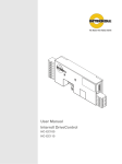
Principle of zones
Zone A has a package at the photoeye. The 9007 of zone A
recognizes its presence, checks zone B for availability and requests permission
to transfer the package to zone B. Since zone B has also a package, its
9007 denies the permission until this package has been transfered to
zone C (singulation mode), or has at least started being transfered (enhanced
singulation mode). The singulation method depends on the setting of DIP switch
SW3.
The 9007 of zone A will only start to operate the RollerDrives in its
zone after it gets permission from the 9007 of zone B.
1
2
3
4
8
Zone
Direction of travel
Load
RollerDrive
5
6
7
8
Photoeye
HC-DriveControl
Peer-to-peer communication cable
+24 VDC / GND
Version 1.1 (11/2011) en
Original language
9007 Hybrid Control for RollerDrive
Product information
Product description
Features
•
•
•
•
•
•
•
•
•
•
Operation modes
Version 1.1 (11/2011) en
Original language
Zone-to-zone communication: Activities in upstream and downstream zones
are monitored by photoeyes to permit control in various situations.
Learn Mode: During system startup, the 9007 will automatically set the zone
length and save it, simply by running an object from the upstream photoeye
to the downstream photoeye.
Diagnostics: LEDs provide motor, sensor, and jam diagnostics as well as
power, fuse, and temperature status.
Reverse or jog entire system: Switch settings and connections on the board
allow the user to reverse the zone-to-zone logic, jog the entire system, or
reverse or jog parts of the system, or bypass those functions altogether
(default) without the use of external cards.
NPN or PNP: All inputs and outputs can be switched, collectively, for NPN or
PNP with one switch. Only "No fault output" is always active high (failsafe
function with 24 VDC in "No fault status").
Multiple dependent RollerDrives in one zone: Up to three RollerDrives can
be run from one 9007 (and two dependent cards) to achieve
multiple RollerDrives in a single zone. This signal can also be used by a PLC
as a "motor running" status input.
Smart braking: Depending on upstream and downstream zone occupancy,
the RollerDrive will brake if needed, and coast if no braking is required. This
saves on power, heat, and vibration in the RollerDrive and ultimately in the
system. When no photoeyes are blocked in the system, all RollerDrives are in
coast mode.
Dynamic braking: RollerDrive acts like a generator and the 9007 feeds
back current into the RollerDrive windings.
Zero motion hold: When the 9007 has no start signal, the RollerDrive
will be held in place.
Advanced braking: The combination of dynamic braking followed by zero
motion hold provides superior braking and holding for many applications.
The operation modes of a RollerDrive conveyor with 9007 Hybrid Controls include:
• Standby: The RollerDrives are turned off if the zone is empty.
• Accept: When a load reaches the sensor at the upstream end of the zone, the
RollerDrives turn on to accept it.
• Transfer: The RollerDrives continue to run to ensure that the load entering
the upstream end of the zone is transferred to the downstream end. This
creates a smooth transition and high throughput.
• Discharge: The RollerDrives in the zone continue running to discharge the
load if no accumulation command is received from the downstream zone.
9
9007 Hybrid Control for RollerDrive
Product information
Safety and stall functions
There are different levels of over-temperature or stall-related functions:
• Jam protection: If the 9007 detects a jam or obstruction at the
downstream end of the zone, it sends an accumulation signal to the upstream
zone, preventing a build-up of accumulation pressure that could cause
product damage or personal injury.
• Motor temperature foldback: At a motor temperature of 80 °C (176 °F) the
9007 will fold back peak current down to continuous current. This is
indicated by the amber LED lighting up constantly. When the RollerDrive cools
down, the amber LED extinguishes, and the maximum peak current is now
possible again. The motor can run at this reduced current limit indefinitely
without harming the 9007 or the motor.
• Motor temperature shutdown: At a motor temperature of 100 °C (212 °F)
the 9007 will shut down the motor and the motor will go into
dynamic braking. This is indicated by the red led flashing five times. When the
RollerDrive cools back down, the red LED stops flashing and motor operation
will resume.
• Motor stall current limiting: When the motor is stalled, the current will fold
back to 1.4 A until the stall is cleared.
• 9007 temperature foldback: At a card temperature of 70 °C (158 °F)
the 9007 will foldback peak current down to continuous current. This is
indicated by the amber LED lighting up constantly. When the 9007
cools down, the amber LED extinguishes, and the maximum peak current is
now possible again. The 9007 can run at this reduced current limit
indefinitely without harming the 9007 or the motor.
• 9007 temperature shutdown: At a 9007 temperature of
90 °C (194 °F) the 9007 will shutdown the motor and the motor will go
into dynamic braking. This is indicated by the red LED flashing four times.
When the 9007 cools back down the red LED stops flashing and motor
and 9007 operation will resume.
Incline and decline applications
Due to the zero motion hold and regenerative braking features, the
9007 and RollerDrive EC1xx can be used for incline and decline
applications up to an angle of 15°.
10
Version 1.1 (11/2011) en
Original language
9007 Hybrid Control for RollerDrive
Product information
Inputs and outputs
Power input and I/O
connections
8
7
6
3
This input is PNP/NPN selectable (with DIP switch 1).
REV input: Invokes the system reverse function, causing all interconnected
controls to operate in reverse transport mode while the signal is active.
When in dependent mode, the motor will simply run in reverse while this
signal is active. This input is PNP/NPN selectable (with DIP switch 1).
No fault output: Active high (+24 VDC) when either in NPN or PNP mode.
Signal goes low only when system faults occur.
Smart 1 output: Has various functions depending on zone type:
• In entry zone: reflects the status of the zone (occupied or free) for
handshake with previous systems.
• In exit zone: reflects the status of the zone (occupied or free) for
handshake with following systems.
• In transport zone: is the connection to control a second RollerDrive in the
zone by interfacing with Smart 1 IN of the dependent zone.
• In dependent zone: reflects the status of the sensor.
2
1
This output is PNP/NPN selectable (with DIP switch 1).
Common ground input: Must be connect to the main power ground.
+24 VDC input: Main power supply 24 VDC (voltage range see "Technical
data", page 17).
5
4
Version 1.1 (11/2011) en
Original language
Speed analog input: External speed control down to approximately 33% of
the maximum speed. When using a 10 kΩ external potentiometer, the wiper
must be connected here. The on-board rotary switch should be set to
maximum (CW) so it will not affect the external speed setting (for the wiring
diagrams see page 19).
Sensor out: Mimics the Sensor 1 input signal from pin 4 on the sensor
connection. Unchanged by zone type. (see sensor connections page 12).
Smart 1 / FWD input: Has various functions depending on zone type:
• In entry zone: acts as a start signal for the handshake with previous
machines or conveyors.
• In exit zone: acts as a start signal to discharge the conveyor as
handshake to following systems.
• In transport zone: acts as jog signal for the specific zone or the whole
conveyor (depending on the DIP switch settings)
• In dependent zone: acts as jog command to run the motor.
11
9007 Hybrid Control for RollerDrive
Product information
Hint
The 9007 is protected against reverse polarity, but the power supply
must provide a short circuit or over current protection and a voltage ripple
tolerance of less than 5%.
Sensor connection
6
5
4
3
2
1
Accum (L-stop) input: An active signal (NPN/PNP switchable) on this
terminal input will cause the 9007 to accumulate in this zone until
the signal is removed. A manual switch or a PLC controller can provide the
signal referenced to a common DC ground (NPN) or +24 VDC (PNP). This
input is PNP/NPN selectable (with DIP switch 1).
Sensor 2 input: Used as a start sensor. It is located at the upstream edge of
the zone and tells the first zone in a conveyor to run. This input is PNP/NPN
selectable (with DIP switch 1).
Sensor 1 input: Located at the downstream edge of the zone. This input is
PNP/NPN selectable (with DIP switch 1).
Motor run output: Output to tell PLC that the motor is running.
Unchanged by zone type. This input is PNP/NPN selectable (with DIP switch 1).
Sensor common ground output: Power ground connection for sensor 1 and
sensor 2.
Sensor +24 VDC output: +24 VDC power supply for sensor 1 and sensor 2.
Hint
Only the sensors mentioned below may be chosen: (sensor supply current from
the board is 50 mA max)
• NPN retro reflective (reflector required) - light operate, normally open (NO)
contact
• NPN diffused (no reflector) - dark operate, normally closed (NC) contact
• PNP retro reflective (reflector required) - light operate, normally open (NO)
contact
• PNP diffused (no reflector) - dark operate, normally closed (NC) contact
12
Version 1.1 (11/2011) en
Original language
9007 Hybrid Control for RollerDrive
Product information
Peer-to-peer communication
Even though all of the external inputs and outputs are NPN and PNP switchable,
the 9007 peer-to-peer communications always use NPN TTL logic.
This means that if a signal passing from board to board is high, it is not in
operation. If it is low (grounded), it is either performing its designated function or
sending the function signal to a nearby board.
All logic operates from a regulated and filtered 5 VDC power supply on the
9007. The 5 VDC power is delivered by a converter on the board
which converts the 24 VDC power that the board receives into 5 VDC for the
internal logic and peer-to-peer board communications (For communication cable
hardware see "Accessories", page 46).
Downstream peer-to-peer
6
5
4
3
2
1
Jog (I/O) [left]
Reverse (I/O)
Accumulation (I/O)
B sensor (OUT)
Ground
NPN (IN) [right]
Upstream peer-to-peer
1
2
3
4
5
6
Jog (I/O) [right]
Reverse (I/O)
Accumulation (I/O)
C sensor (IN)
NPN (IN)
Ground [left]
Hint
While different segments of a system may operate at different input voltages, the
DC ground for each system must be held at the same potential (0 VDC) to ensure
good operation and clean signals. In other words, when multiple power supplies
are used, the DC grounds must always be connected together.
Hint
When a peer-to-peer port is connected to another ZPA product, the NPN (in)
signal is pulled low except for the case where a 9007 is upstream.
Version 1.1 (11/2011) en
Original language
13
9007 Hybrid Control for RollerDrive
Product information
DIP switches
The DIP switches allow the selection of various types of control operations. The
default DIP switch settings are all OFF. This would provide:
• RollerDrive selection of an EC100 (SW6, SW7)
•
Standard 9007 connectivity upstream and downstream (SW4, SW5)
• Standard singulate mode (SW3)
• Motor running counter clockwise (SW2)
• All NPN inputs and outputs (SW1)
Hint
DIP switch settings are read at reset (power-up) only.
The following table shows the switch position for different situations:
14
DIP switch
ON (up position
OFF (down position)
SW5
Downstream
Jog/Rev ON: the downstream
peer-to-peer cable is connected
to another 9007 and
the jog/reverse signal is
transmitted
Standard: the jog/reverse
signal is not transmitted
SW4
Upstream
Jog/Rev ON: the upstream
Standard: the jog/reverse
peer-to-peer cable is connected signal is not transmitted
to another 9007 and
the jog/reverse signal is
transmitted
SW3
Singulation
Enhanced: enhanced
singulated release (see
"Glossary", page 47) is needed
SW2
Rotation
Clockwise: (rotation of the
Counter clockwise: (rotation
RollerDrive seen from the cable of the RollerDrive seen from
end)
the cable end)
SW1
Logic
PNP: all external inputs,
photoeye inputs and outputs
are active high (24 VDC)
Standard: singulated release
(see "Glossary", page 47) is
needed
NPN: all external inputs,
photoeye inputs and outputs
are active low (0 VDC
ground).
This excludes the "No fault
output" which is always active
high (+24 VDC) when in either
NPN or PNP mode.
Version 1.1 (11/2011) en
Original language
9007 Hybrid Control for RollerDrive
Product information
•
•
•
•
Local jog and reverse are always enabled, but upstream and downstream
propagation are controlled by DIP switch 4 and DIP switch 5 respectively.
It is now simple to use DIP switch 4 and DIP switch 5 to define jog/reverse
groups, or to defeat jog and reverse completely (recommended whenever not
in use).
If the RollerDrive is mounted with the cable exiting the opposite side of the
conveyor frame, switch SW2 has to be set in the opposite position to maintain
equal direction of travel.
For special cases see "Setting options and wiring diagrams", page 20
Rotary switches (16 position)
Version 1.1 (11/2011) en
Original language
15
9007 Hybrid Control for RollerDrive
Product information
Meaning of the LEDs
The LEDs provide motor, sensor, and jam diagnostics as well as power, fuse, and
temperature status. The following table shows the meaning of the LEDs (flashes
are ¼ second on, and ¼ second off, in a fixed 4 second time period):
LED
Color
Status
Meaning
Fuse
red
on steady (all other
LEDs are off)
Fuse blown
Power
green
on steady
Power ok
Fault
red
on steady
Stalled motor
Jam at or between sensors
Peer-to-peer cable unplugged
Warning
flashing once
Motor or motor cable open or
disconnected
flashing twice
Over-voltage detection
29 VDC ± 0.2 VDC (will cease
normal operation)
flashing three times
Under-voltage detection
19 VDC ± 0.2 VDC (will cease
normal operation)
flashing four times
9007 severe temperature
shut-down (will cease normal
operation until cool)
flashing five times
Motor severe temperature shutdown (will cease normal
operation until cool)
flashing six times
Low gain or bad sensor (sensor
with fault output connected)
amber on steady
flashing four times
Motor current is limited to
maximum continuous current due
to motor over-temperature
Motor current is limited to
maximum continuous current due
to card over-temperature
There is no error output if the amber LED is flashing.
16
Version 1.1 (11/2011) en
Original language
9007 Hybrid Control for RollerDrive
Product information
9007 label
The specifications on the 9007 label are used to identify the
9007. This is required to use the 9007 as intended.
1
2
3
4
5
6
1
2
3
Technical data
Version 1.1 (11/2011) en
Original language
17
9007 Hybrid Control for RollerDrive
Product information
Speed settings
On board speed setting
The speed can be continuously adjusted (between 100% and 33% for the
EC100, EC110, and EC120) by the rotary switch marked "speed" on the
9007. Default setting is maximum.
Hint
If more than one 9007 has to run with reduced speed, it is recommended
to set the speed externally (by PLC or external potentiometer; see "External
speed setting", page 19).
18
Version 1.1 (11/2011) en
Original language
9007 Hybrid Control for RollerDrive
Product information
External speed setting
Apart from the rotary switch on the 9007, there are other ways to set the
speed.
HintF
For the meaning of the settings see "DIP switches", page 14.
Version 1.1 (11/2011) en
Original language
19
9007 Hybrid Control for RollerDrive
Product information
Setting options and wiring diagrams
This chapter explains the DIP switch settings for different application
Hint
When the DIP switch settings ON / OFF are stated, both settings are possible for
the shown wiring (for the meaning of the settings see "DIP switches", page 14).
9007 is between
two 9007 Cards
20
Upstream device
9007
Downstream device
9007
DIP switch 4
Off
On
Off
On
DIP switch 5
Off
On
On
Off
Upstream peer-to-peer jog/ Disabled
reverse
Functional
Disabled
Functional
Downstream peer-to-peer
jog/reverse
Disabled
Functional
Functional
Disabled
Zone type
ZPA-mode
ZPA-mode
ZPA-mode
ZPA-mode
Smart 1 (in)
Jog
Jog
Jog
Jog
Reverse (in)
System
reverse
System
reverse
System
reverse
System
reverse
Smart 1 (out)
Motor run
Motor run
Motor run
Motor run
Sensor 2
Another
C sensor
Another
C sensor
Another
C sensor
Another
C sensor
Version 1.1 (11/2011) en
Original language
9007 Hybrid Control for RollerDrive
Product information
DIP switch settings:
• SW1: ON
Version 1.1 (11/2011) en
Original language
21
9007 Hybrid Control for RollerDrive
Product information
DIP switch settings:
• SW1: OFF
22
Version 1.1 (11/2011) en
Original language
9007 Hybrid Control for RollerDrive
Product information
DIP switch settings:
• If SW5 is ON, direction setting is transferred downstream.
• If SW4 is ON, direction setting is transferred upstream.
• SW1: ON
Start options:
• FWD connected to 24 VDC at PNP mode causes ccw rotation.
• REV connected to 24 VDC at PNP mode causes cw rotation.
• FWD and REV connected to 24 VDC at PNP mode causes coast mode.
Hint
•
•
Version 1.1 (11/2011) en
Original language
FWD signal acts like a jog signal, disregarding ZPA functionality and photoeye
signals.
REV signal reverses motor and logic direction; upstream becomes
downstream and C sensor becomes B sensor.
23
9007 Hybrid Control for RollerDrive
Product information
DIP switch settings:
• If SW5 is ON, direction setting is transferred downstream.
• If SW4 is ON, direction setting is transferred upstream.
• SW1: OFF
Start options:
• FWD connected to GND at NPN mode causes ccw rotation.
• REV connected to GND at NPN mode causes cw rotation.
• FWD and REV connected to GND at NPN mode causes coast mode.
Hin
t
•
•
24
FWD signal acts like a jog signal, disregarding ZPA functionality and photoeye
signals.
REV signal reverses motor and logic direction; upstream becomes
downstream and C sensor becomes B sensor.
Version 1.1 (11/2011) en
Original language
9007 Hybrid Control for RollerDrive
Product information
Works like a standard configuration, only the 9007 is turned upsidedown.
Version 1.1 (11/2011) en
Original language
25
9007 Hybrid Control for RollerDrive
Product information
Hint
A reverse command to the Zone 9007 will not be communicated to the
dependent 9007 cards.
Dependent 9007 DIP switch settings:
• SW1: Must have the same switch setting as zone 9007 (logic mode
NPN or PNP).
26
Version 1.1 (11/2011) en
Original language
9007 Hybrid Control for RollerDrive
Product information
Start options:
• FWD connected to 24 VDC causes ccw rotation.
• REV connected to 24 VDC causes cw rotation.
• FWD and REV connected to 24 VDC causes coast mode.
Version 1.1 (11/2011) en
Original language
27
9007 Hybrid Control for RollerDrive
Product information
9007 is entry zone
Upstream device
-
-
Downstream device
-
-
9007
DIP switch 4
Off
On
Off
On
DIP switch 5
Off
On
On
Off
Upstream peer-to-peer jog/ Disabled
reverse
Functional
Disabled
Functional
Downstream peer-to-peer
jog/reverse
Disabled
Functional
Functional
Disabled
Zone type
Smart I/O
entry
ZPA-mode
Smart I/O
entry
ZPA-mode
Smart 1 (in)
Request
Jog
Request
Jog
Reverse (in)
System
reverse
System
reverse
System
reverse
System
reverse
Smart 1 (out)
Perm.
Motor run
Perm.
Motor run
Sensor 2
Not used
Another
(smart I/O) C sensor
Not used
Another
(smart I/O) C sensor
DIP switch settings:
• SW4: ON / OFF (specifies if this zone is a transport or entry zone; if
sensor 2 IN is used, SW4 must be set to ON)
Sensor 2 IN start signal (by PLC or photoeye):
• Start signal for PNP: 24 VDC
• Start signal for NPN: GND
Hint
If you are using a photoeye as a starting signal, connect sensor 2 IN with the
photoeye.
28
Version 1.1 (11/2011) en
Original language
9007 Hybrid Control for RollerDrive
Product information
9007 is exit zone
9007
Upstream device
Downstream device
-
-
-
-
DIP switch 4
Off
On
Off
On
DIP switch 5
Off
On
On
Off
Upstream peer-to-peer jog/ Disabled
reverse
Functional
Disabled
Functional
Downstream peer-to-peer
jog/reverse
Disabled
Functional
Functional
Disabled
Zone type
Smart I/O
exit
ZPA-mode
ZPA-mode
Smart I/O
exit
Smart 1 (in)
Perm.
Jog
Jog
Perm.
Reverse (in)
System
reverse
System
reverse
System
reverse
System
reverse
Smart 1 (out)
Request
Motor run
Motor run
Request
Sensor 2
Another
C sensor
Another
C sensor
Another
C sensor
Another
C sensor
DIP switch settings:
• SW5: ON / OFF (specifies if this zone is a transport or exit zone)
Smart 1 IN signal (by PLC or photoeye):
• Start signal for PNP: 24 VDC
• Start signal for NPN: GND
Version 1.1 (11/2011) en
Original language
29
9007 Hybrid Control for RollerDrive
Product information
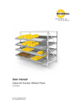
Learn Mode Reset
30
At startup "Learn Mode" automatically sets the zone length, and saves it, simply
by running an object from the upstream sensor to the downstream sensor. If the
sensor positioning or zone length should change after startup, you must reset
the learn mode. Simply remove the two screws from the cover to reveal the two
pin header shown below. Carefully short these two pins together until you see
the LED's flash. Immediately remove the short. You are now ready to run an
object from the upstream sensor to the downstream sensor to "re-learn" the
zone length.
Version 1.1 (11/2011) en
Original language
9007 Hybrid Control for RollerDrive
(this page intentionally left blank)
Version 1.1 (11/2011) en
Original language
31
9007 Hybrid Control for RollerDrive
Product information
9007 in
conjunction with PLChandshakes
9007 after
PLC-handshake (entry zone)
9007 before
PLC-handshake (exit zone)
9007
between PLChandshakes
Upstream device
PLC
PLC
9007
9007
PLC
Downstream device
9007
9007
PLC
PLC
PLC
DIP switch 4
Off
Off
Off
On
Off
DIP switch 5
Off
On
Off
Off
Off
Upstream peer-to-peer jog/reverse
Disabled
Disabled
Disabled
Functional
Disabled
Downstream peer-to-peer jog/
reverse
Disabled
Functional
Disabled
Disabled
Disabled
Zone type
Smart I/O
entry
Smart I/O
entry
Smart I/O
exit
Smart I/O
exit
Smart I/O
dependent
Smart 1 (in)
Request
Request
Perm.
Perm.
Run
Reverse (in)
System
reverse
System
reverse
System
reverse
System
reverse
System reverse
Smart 1 (out)
Perm.
Perm.
Request
Request
B sensor
Sensor 2
Not used
(smart I/O)
Not used
(smart I/O)
Another
C sensor
Another
C sensor
Not used
32
Version 1.1 (11/2011) en
Original language
9007 Hybrid Control for RollerDrive
Product information
•
•
•
Version 1.1 (11/2011) en
Original language
A smart I/O based handshake is required at the interface
DIP switch 4 must be OFF to make this zone into an entry zone
Jog and reverse are enabled only if DIP switch 5 is ON
33
9007 Hybrid Control for RollerDrive
Product information
•
•
•
34
A smart I/O based handshake is required at the interface
DIP switch 5 must be OFF to make this zone into an exit zone
Jog and reverse are enabled only if DIP switch 4 is ON
Version 1.1 (11/2011) en
Original language
9007 Hybrid Control for RollerDrive
Product information
•
•
Version 1.1 (11/2011) en
Original language
A smart I/O based handshake is required at both interfaces
DIP switch 4 and DIP switch 5 must both be OFF to make this zone into a
dependent zone.
35
9007 Hybrid Control for RollerDrive
Transport and storage
Transport
Transport and storage
•
Each 9007 is packed in its own carton case.
CAUTION
Risk of injury due to improper transport
Transport may only be carried out by qualified and
authorized persons.
Observe the following notices.
Do not stack more than four carton boxes.
Check the fixation of the 9007 before transport.
Avoid hard shocks during transport.
Check each 9007 visually for damage after transport.
In case of damage, take photos of the damaged parts.
To maintain the warranty, instantly report any damage caused during
transport to the transport company and to Interroll.
Do not transfer the 9007 between warm and cold environments as
this may cause condensing water.
Storage
CAUTION
Risk of injury due to improper storage
Do not stack more than four carton boxes.
Check each 9007 for damage after storage.
36
Version 1.1 (11/2011) en
Original language
9007 Hybrid Control for RollerDrive
Assembly
Warning notices concerning assembly
Assembly
Risk of damage leading to failure or shortened life
expectancy of the 9007
Observe the following notices.
Do not drop or mishandle the 9007 to avoid internal damage.
Check each 9007 visually for damage before assembly.
Warning notices concerning the electrical installation
Risk of damage to the 9007
Observe the following notices.
The electrical installation may only be executed by qualified and authorized
persons.
Disconnect the power before installing, removing or rewiring the 9007.
Do not apply AC current to the RollerDrive or 9007 device at any time
as this will cause irreparable damage.
Do not apply too much stress to the connector pins. Bending the wires at the
connector can cause damage to the insulation of the wires, which could result
in failure of the 9007 or the RollerDrive.
Ensure that the RollerDrive, the 9007 and the 24 VDC power source
are properly earthed through the frame or supporting structure in which the
RollerDrive and the 9007 are installed. Failure to do so could cause
the buildup of static electricity or ground loops and can cause the motor or
9007 to malfunction or fail prematurely.
Do not spin the RollerDrive manually, as this generates an induction voltage
which could damage the 9007.
Version 1.1 (11/2011) en
Original language
37
9007 Hybrid Control for RollerDrive
Assembly
Installing the 9007 Hybrid Control in a conveyor system
Use the 9007 as a template and mark the center of the two mounting
holes. For the distance between the holes, see "Dimensions", page 7.
Drill two ø 5.6 - 6 mm (0.22 - 0.24 in) mounting holes at the marked spots.
Insert the button head screws in the holes on the opposite side the
9007 is to be mounted.
Install the 9007 to the frame with the screws protruding through the
mounting holes.
Slip the nuts to the screws and tighten.
Ensure that there is a ground path between the 9007 and the conveyor
frame it is mounted to.
Hint
The 9007 and conveyor frame should be at the same potential referenced
to earth ground.
Electrical installation
The connector supplied with the RollerDrive EC1xx mates up with the header on
the 9007.
The connectors "Power input and I/O terminal" and "Sensor connection" are cage
clamp terminals.
To actuate the cage clamp, use the supplied tool or insert a small screwdriver.
Plug in the RollerDrive connector.
Plug in the peer-to-peer connection cable, if applicable.
38
Version 1.1 (11/2011) en
Original language
9007 Hybrid Control for RollerDrive
Initial startup and operation
Initial startup
Initial startup and operation
Inspections before initial
startup
Ensure that all bolts are tightened according to the specifications.
Ensure that no additional dangerous areas arise due to interfaces with other
components.
Ensure that the wiring is in accordance with specifications and legal
guidelines.
Check all protection devices.
Ensure that no bystanders are in dangerous areas around the conveyor.
Operation
Damage to the 9007 or the motor of the
RollerDrive due to induction
Do not push items along the roller conveyor by hand.
Do not spin the RollerDrive manually.
Inspections before every
startup
Changing settings
Check the position of the DIP switches (see "DIP switches", page 14).
Check the speed settings at the speed rotary switch. It is recommended to
run the RollerDrive at maximum speed.
Check the 9007 for visible damage.
Check all protection devices.
Ensure that no bystanders are in dangerous areas around the conveyor.
Clearly specify and monitor the way goods are placed on the conveyor.
To reduce the speed manually, turn the rotary switch counterclockwise with a
small screwdriver.
To increase the speed manually, turn the rotary switch clockwise with a small
screwdriver.
To set the DIP switches, carefully use a small screwdriver.
Procedure in case of accident or malfunction
Version 1.1 (11/2011) en
Original language
Stop the conveyor at once and ensure that it cannot be started accidentally.
In case of an accident: Provide first aid and call for emergency assistance.
Inform responsible persons.
Have the malfunction repaired by qualified persons.
Start the conveyor only after this has been approved by qualified persons.
39
9007 Hybrid Control for RollerDrive
Maintenance and cleaning
Warnings concerning maintenance and cleaning
Maintenance and cleaning
CAUTION
Risk of injury due to improper handling or accidental
motor starts
Maintenance work and cleaning may only be executed
by qualified and authorized persons.
Only perform maintenance work after switching off the
power. Ensure that the 9007 cannot be turned
on accidentally.
Set up signs indicating maintenance work.
Maintenance
Checking the 9007
The 9007 must be checked at regular intervals to avoid malfunctions.
Monthly check the 9007 and its leads for visible damage.
Annually ensure that the screws of the 9007 are still tight and that the
cables are still laid properly and connected to the terminals.
Replacing the 9007
If a 9007 is damaged, it has to be replaced.
Install a new 9007 (see "Abandonment", page 45 and see "Assembly",
page 37).
Replacing fuse
Carefully use tweezers to remove and insert the fuse. Ensure you do not
damage the fuse holder, the circuit board or its devices.
Cleaning
Dust and dirt in combination with humidity may bridge the electric circuit.
Therefore, in a dirty environment, periodic cleaning will help to avoid shortcircuits which could damage the 9007.
Regularly blow off dust and dirt by using low compressed air.
40
Version 1.1 (11/2011) en
Original language
9007 Hybrid Control for RollerDrive
Troubleshooting
Error search
Troubleshooting
When troubleshooting the conveyor system, keep in mind that each
9007 controls a zone. If a problem exists in a zone or a section of
zones, the symptoms might exist either in the zone or in the neighboring zone.
Hint
Keep in mind that information travels downstream. The cause of most control
problems can be found upstream.
Symptom
Possible cause
Help
System is not operating
No power supply
Check whether the output voltage of the
power supply is within the specified
voltage range.
Wrong polarity of the bus line inputs
Verify the polarity of the bus line inputs
to the 9007 (see "Inputs and
outputs", page 11).
Wrong position of the DIP switch 1
Verify that the position of the DIP switch
1 Logic (NPN or PNP) matches the
sensor type (see "DIP switches",
page 14).
Fuse is blown
Replace the fuse (see "Replacing fuse",
page 40).
Wrong sensor output
Check the type of sensor output (see
"Sensor connection", page 12).
Wrong alignment of sensors
Verify the alignment of the sensors.
Align the photoeyes to see the conveyor
field only, no overhead lights, side
frames, etc.
Jog command by an inadvertently
grounded Smart 1 / FWD input
command
Check the connection of Smart 1 / FWD
input
Communication cable is twisted or
defective
Check the communication cable
upstream
Photoeye is not connected properly
Check the connection of the photoeye to
9007. Verify the photoeye
pin assignment (see "Sensor
connection", page 12).
Photoeye is damaged
Replace the photoeye.
If the zone continues to run without
any communication cables
connected and no photoeye input,
9007 is damaged.
Replace 9007. Assembly of
the 9007 see "Assembly",
page 37.
Zone runs without package
Version 1.1 (11/2011) en
Original language
41
9007 Hybrid Control for RollerDrive
Troubleshooting
Symptom
Possible cause
Help
Multiple zones run continuously
Communication cable is defective,
sending a jog command
Find the farthest zone in the upstream
direction that is running continuously.
Check the communication cables of this
zone.
Different ground of a multiple power
supply
Verify that a common ground is shared
by all supplies.
Fuse is blown
If DIP switch 4 and 5 are ON for all
cards, a blown fuse or loss of power
in one 9007 sends a reverse
jog command to all 9007 cards in
the system.
Check the fuses in all 9007 cards of
the system and replace the blown one
(see "Replacing fuse", page 40).
Miswired communication cable
Check the communication cables in the
entry zone of the system. Replace the
miswired cables.
Zone receives the accumulate signal
Check that the zone is not receiving the
accumulate signal from the downstream
zone.
Ensure that there is no jumper installed
from ground to the Accum (L-stop) input
terminal on the 9007 of the
zone where the package stops. If a
switch is used instead of a jumper,
check that the switch is off.
Communication cable to or between
the zones is miswired
Check the communication cables and
replace them if they are miswired.
No power supply of the
9007
Check the power input to
9007
No power supply of the RollerDrive
EC1xx
Verify that the motor wires are
terminated properly.
Communication cable is miswired
between the zone that is operating
and the zone that is not
Replace the cable.
Photoeye is not aligned properly
Check the alignment of the photoeye.
Speed of the RollerDrive EC1xx is
too slow
Calculate the speed and the distance to
ensure the time limit is not exceeded.
Reset "Learn Mode" (see "Learn Mode
Reset, page 30)
Jammed package
Remove jammed packages.
Jammed roller
Remove the cause of the jam or replace
the roller.
System reverses or jogs without
prompting
Zone stops when package arrives
Zone does not accept package
Package stops within a zone
42
Version 1.1 (11/2011) en
Original language
9007 Hybrid Control for RollerDrive
Troubleshooting
Symptom
Possible cause
Help
Package coasts into the next zone
instead of stopping immediately
Package is heavy or has a low
coefficient of friction
Move the photoeye further back into the
zone.
Apply a coating that increases the
friction between the rollers and the
packages.
Zone does not reverse
Communication cable to upstream
zone is miswired
Replace the communication cable.
Signal has not been sent and
received properly
Check the output of the upstream
9007 and the input to the
9007.
Different ground of the zones
Check that a common ground exists
between both zones.
System turns off when several zones
are in use at the same time
Power supply is not sufficient
Ensure that the 24 VDC power supply
has adequate power for the system
requirements.
Check that the AC voltage source and
DC voltage power supply are installed
correctly.
9007 does not recognize the
start sensor
Sensor and reflector are not aligned
properly
Check the alignment of the sensor and
reflector.
Check the settings of DIP switch 4
and 5.
RollerDrive EC1xx is not in braking
mode without any packages on the
conveyor system
This is not an error. It is a powersaving feature. The RollerDrive
EC1xx is in coast mode until it is
commanded to run or accumulate.
Version 1.1 (11/2011) en
Original language
43
9007 Hybrid Control for RollerDrive
Troubleshooting
The following errors are reported by illuminated LEDs:
(also see "Meaning of the LEDs", page 16)
Symptom
Possible cause
Help
Motor is in brake mode, red fault
LED flashes once and error output is
active ("No fault output" is active).
Invalid state of motor hall effect
sensor
• Broken wire
• Failed hall effect sensor
Replace the RollerDrive.
Voltage over or under limits
• Power supply fluctuations, failure
or overload condition
Check the power supply.
On a decline, motor is in brake mode
momentarily. Red fault LED flashes
twice ("No fault output" is active) or
power supply shutdown or fuse
blown on card.
Overvoltage detection (caused by
over speed or excessive back EMF)
• decline angle too high
• package weight too high
•
•
Motor overrun, overset speed
• Package enters zone at a higher
than anticipated speed
Reduce the package entry speed.
Red fault LED flashes six times and
error output is active ("No fault
output" is active).
Low gain signal from sensor
• Dirty sensor lens or misaligned
Clean the sensor lens and align the
sensor.
Current folds back to maximum
continuous current, amber fault LED
is on.
Card or motor over temperature
• Excessive load or duty cycle
Reduce the load of packages or
throughput of the zone
Current folds back to approximately
1.5 A while applying consistent
torque. Red fault LED is on and error
output is active ("No fault output" is
active).
Motor stall condition
• Obstruction or load too heavy to
be conveyed
Once the stall condition is removed, the
RollerDrive will resume normal
operation.
44
Reduce decline angle
Use brake roller to keep speed low
Version 1.1 (11/2011) en
Original language
9007 Hybrid Control for RollerDrive
Abandonment and disposal
Abandonment
Abandonment and disposal
CAUTION
Risk of injury due to improper handling
Abandonment may only be executed by qualified and
authorized persons.
Only abandon the 9007 after switching off the
power. Ensure that the 9007 cannot be turned
on accidentally.
Disconnect all cables from the 9007.
Unscrew the screws attaching the 9007 to the conveyor frame.
Extract the 9007 from the conveyor frame.
Disposal
The operator is responsible for the proper disposal of the 9007. In doing
so, industry-specific and local provisions must be observed for the disposal of the
9007 and its packaging.
Version 1.1 (11/2011) en
Original language
45
9007 Hybrid Control for RollerDrive
Appendix
Appendix
Accessories
Plugs and cables
Part
Description
Power and I/O plug
•
•
Sensor plug
•
•
Peer-to-peer cable
(parts)
•
•
•
•
Peer-to-peer cable
(preassembled)
•
•
Motor plug
•
•
46
8-pin cage clamp type connector, Wago part #
231-308/026-004
Wire diameter:
– Minimum 0.08 mm2 (AGW 28)
– Maximum 2.5 mm2 (AGW 12)
6-pin cage clamp type connector, Wago part #
734-106/000-004
Wire diameter:
– Minimum 0.08 mm2 (AGW 28)
– Maximum 1.5 mm2 (AGW 14)
Cable: 6 pos flat cable, Digikey part # A0063R
Two plugs: 6 pos modular connector plug,
Digikey part # A9093-ND
Conductor Size AWG: 26
Assembly tool: AMP part # 2-231652-8
Complete cable: 6 pos flat cable,
with (2) 6 pin modular plugs,
Digikey part # A1663R-03-ND (03 = 3 foot length)
www.digikey.com
The motor plug for the RollerDrive consists of a
plug and terminal pins
– Plug: AMP part # 175778-8
– Terminal pins: AMP part # 1-175102-1
Crimping tool AMP part # 9184381
Version 1.1 (11/2011) en
Original language
9007 Hybrid Control for RollerDrive
Appendix
Glossary
Back EMF
B sensor
Downstream edge presence sensor of own zone
C sensor
Downstream edge presence sensor of upstream zone
Coast mode
The RollerDrive is running freely without power or braking.
DIP switch 4
Affects upstream peer-to-peer propagation of speed, jog and reverse signals
for certain scenarios.
DIP switch 5
Affects downstream peer-to-peer propagation of speed, jog and reverse signals
for certain scenarios.
Downstream
Normally this is the zone to the left of another given zone. The reference is
always that packages move from upstream to downstream.
Dynamic braking
EC1xx
Edge full
Enhanced Singulated release
Foldback current
Version 1.1 (11/2011) en
Original language
Electromotive force (voltage) generated by a package arriving at high speed at
a powered RollerDrive under no load prior to the package’s arrival. EMF is a
counter-voltage phenomenon that is always present in a motor. Excessive back
EMF can cause a current backlash that may damage the 9007 or power
supply. Care should be taken to minimize excessive back EMF by minimizing
the speed differences between the gravity conveyor and/or different zones of
powered conveyor sections.
For DC motors, dynamic braking is a method of stopping a motor by applying a
resistive load across the motor winding leads after disconnection from the DC
supply. The motor operates as a generator. By its nature, dynamic braking has
no holding power by itself, i.e. the motor can still be rotated by outside forces.
Interroll has added zero motion hold to achieve this.
Short form for Interroll 24 VDC brushless RollerDrive versions:
• EC100
• EC110
• EC120
Also referred to as "product waiting". It indicates that an upstream zone has a
product at its downstream edge sensor waiting to be moved into the next
downstream zone. Edge full is a signal transmitted across the peer-to-peer
cable used by the 9007 for zone-to-zone communication.
Also called wave release. A method of release which allows the upstream
release of a package as soon as the downstream package blocks the photoeye
of the downstream zone with its leading edge. This dramatically increases
throughput over singulated release but can sometimes result in lost packages.
There is also a short delay that is propagated upstream to eliminate all
packages starting at the exact same time.
Maximum allowable current is decreased by the 9007.
47
9007 Hybrid Control for RollerDrive
Appendix
Idler rollers
Jam protection
A method of protecting packages that are possibly jammed in a zone. If the
9007 detects a jam or obstruction at the downstream end of the
zone, it sends an accumulation signal to the upstream zone preventing a
buildup of accumulation pressure.
Jog
RollerDrive runs continuously as long as the command is set. If jog mode is
activated, the 9007 disregards ZPA or photoeye signals.
N/C
No care; affects nothing
NPN-override
O-rings
Perm
Photoeye
Req
RollerDrive
48
Non-powered rollers attached to a RollerDrive typically via O-rings or multi-rip
belts.
DIP switch 4 is for upstream, DIP switch 5 is for downstream.
O-rings made of materials such as polyurethane that connect RollerDrives to
their associated idler rollers.
Permission: Signal to upstream zone to discharge zone (send load).
An ON/OFF sensor that uses light to sense the presence of objects. If the light
beam is broken, an object is present. Usually the light is reflected back to the
sensor via a reflector placed on the opposite side of the conveyor frame from
the sensor itself. The 9007 can use either NPN type or PNP type
photoeyes. NPN sensors indicate an active state by a grounded connection
being made (NPN mode) or a 24 VDC connection being made (PNP mode).
Request from upstream zone to discharge zone in downstream direction.
One of several types of DC powered rollers manufactured by Interroll
Corporation.
Singulated release
A method of releasing packages where packages are allowed into downstream
zone only after the trailing edge of the package currently occupying that
downstream zone clears the zone's downstream edge sensor.
Singulation
DIP switch 3 chooses either standard or enhanced singulation, significant for all
zone types except smart I/O dependent.
Upstream
The opposite of "downstream" (see definition). Typically, the zone to the right of
another zone.
Zero motion hold
For DC motors, zero motion hold is a method of holding a motor by applying a
small amount of current to the motor winding leads. When the 9007
is commanded to stop and accumulate, the braking action is twofold. First, the
motor/package is stopped using dynamic braking. Second, the motor is held in
place by zero motion hold. In this state the 9007 will resist being
rotated by outside forces.
Zone
A segment of conveyor typically comprised of one RollerDrive and multiple idler
rollers interconnected by O-rings or some other device for driving the idlers.
ZPA
Zero pressure accumulation: The process of moving packages on a conveyor in
such a manner that they do not touch each other (also see "ZPA technology",
page 7).
Version 1.1 (11/2011) en
Original language
9007 Hybrid Control for RollerDrive
Appendix
Manufacturer's declaration
in terms of the EC-Machine Directive 98/37/EC and its amendment 98/79/EC,
Annex II B
The manufacturer:
Interroll Corporation
3000 Corporate Drive
Wilmington, NC 28405
USA
hereby declares with sole responsibility that the product range
•
9007 Hybrid Control for RollerDrive
is not a ready-to-use assembly in terms of the EC-Machine Directive and
therefore does not fully comply with the requirements of this directive. It
must not be put into service until the machinery into which it is to be
incorporated has been declared to conform with the provisions of the
Machine Directive.
Applied EC Directives:
Machine Directive 98/37/EC and its amendment 98/79/EC
Low Voltage Directive 2006/95/EC
EMC Directive 2004/108/EC
RoHS Directive 2002/95/EC
Applied harmonized norms:
EN ISO 12100 Part1 and Part2
Wilmington, NC, December 20th 2010
Richard Keely
(Vice President of Manufacturing)
(This declaration can be obtained at www.interroll.com, if needed.)
Version 1.1 (11/2011) en
Original language
49
Europe/Nordic
Denmark
Interroll Nordic A/S
Hammerholmen 2-6
DK-2650 Hvidovre/Denmark
Tel. +45 36 88 33 33
Fax +45 36 88 33 72
[email protected]
Interroll Service
Islandsvej 5
DK-7900 Nykøbing M.
Tel. +45 97 71 15 55
Fax +45 97 71 16 55
[email protected]
Iceland
IBH ehf
Dugguvogur 10
104 Reykjavik
Iceland
Tel. +354 562 6858
Fax +354 562 6862
[email protected]
Finland
Tel. +358 9 54 94 94 00
Fax +358 9 54 94 94 16
Norway
Tel. +47 32 88 26 00
Fax +47 32 88 26 10
Sweden
Tel. +46 35 227077
Fax +46 35 227078
Western/Southern Europe
France
Interroll S.A.S.
ZI de Kerannou
B.P. 34
F-29250 Saint Pol de Léon
Tel. +33 298 24 41 00
Fax +33 298 24 41 02
[email protected]
Italy
Rulli Rulmeca S.p.A.
Via A. Toscanini, 1
I-24011 Almè (Bg)
Tel. +39 035 4300111
Fax +39 035 545523
[email protected]
Portugal
Rulmeca Interroll de Portugal Lda
Apartado 69, Centro Civico
P-6201-909 Covilhã
Tel. +351 275 330 780
Fax +351 275 990 789
[email protected]
Spain
Interroll España S.A.
Parc Teconològic del Vallès
C/Dels Argenters, 5
Edificio 1, módulos Bp y Cp
E-08290 Cerdanyola del Vallès
Tel. +34 90 211 0860
Fax +34 93 586 4895
[email protected]
United Kingdom
Interroll Ltd.
Brunel Road
Earlstrees Industrial Estate
GB-Corby, Northants NN17 4UX
Tel. +44 1536 200 322
Fax +44 1536 748 515
[email protected]
Central Europe
Germany
Interroll Fördertechnik GmbH
Höferhof 16
D-42929 Wermelskirchen
Tel. +49 2193 23 0
Fax +49 2193 20 22
[email protected]
Austria
Tel. +49 2193 23 187
Fax +49 2193 23 164
Belgium
Tel. +49 2193 23 131
Fax +49 2193 23 164
Luxembourg
Tel. +49 2193 23 190
Fax +49 2193 23 164
Netherlands
Tel. +49 2193 23 151
Fax +49 2193 23 164
Switzerland
Tel. +49 2193 23 190
Fax +49 2193 23 164
Eastern Europe
Czech Republic
Interroll CZ, s.r.o.
Na Řádku 7/3172
CZ-69002 Břeclav
Tel. +420 519 330 210
Fax +420 519 330 211
[email protected]
Hungary
Tel. +36 23 337 891
Fax +36 23 337 892
Poland
Interroll Polska Sp. z o.o.
ul. Płochocińska 85
PL-03-044 Warszawa
Tel. +48 22 741 741 0
Fax +48 22 741 741 1
[email protected]
Slovakia
Tel. +421 2 4363 8102
Fax +421 2 4342 7294
Slovenia
Tel. +386 1 56 56 370
Fax +386 1 56 56 372
Turkey
Rol-er Makina San. Ve. Tic. Ltd. Sti.
Pembegul Sok., Dostlar Apt.
No. 12 D. 10 Suadiye
347 40 Istanbul
Turkiye
Tel. +90 216 386 37 75
Fax +90 216 386 38 22
[email protected]
Near East
Asia
Israel
Interroll (Suzhou) Co. Ltd.
Unit 10B, Modern Industrial Square
No. 333 Xing Pu Road
Suzhou Industrial Park
Suzhou, Jiangsu Province
People’s Republic of China
Postal Code: 215126
Tel. +86 512 6256 0383
Fax +86 512 6256 0385
[email protected]
ComTrans-Tech Ltd.
P.O.B. 17433
Tel-Aviv 61174
Israel
Tel. +972 54 4 27 27 47
Fax +972 3 7 44 08 64
[email protected]
Africa
South Africa
Interroll SA Pty. Ltd.
P.O. Box 327
Isando 1600
37 Director Road, Spartan Ext 2
1619
South Africa
Tel. +27 11 281 9900
Fax +27 11 252 9083
[email protected]
North & South America
USA
Interroll Corporation
3000 Corporate Drive
USA-Wilmington, NC 28405
Tel. +1 910 799 11 00
Fax +1 910 392 38 22
[email protected]
Canada
Interroll Components Canada Ltd.
8900 Keele Street
Unit 2 & 3
Concord, Ontario L4K 2N2
Canada
Tel. +1 905 660 4426
Fax +1 905 660 4159
[email protected]
Interroll Canada Ltd.
Drives & Rollers Canada
1201 Gorham Street
Newmarket Ontario L3Y 8Y2
Canada
Tel. +1 905 727 3399
Fax +1 905 727 3299
[email protected]
Brasil
Interroll Logistica
Elementos para Sistemas
Transportadores Ltda.
Av. Alexandrina das Chagas
Moreira 945
Bairro Distrito Industrial
Pindamonhangaba-SP
Brasil
CEP 12412 - 800
Tel. +55 12 3648 8021
Fax +55 12 3648 8164
[email protected]
For other countries in
South America, please contact:
Interroll España S.A.
Parc Teconològic del Vallès
C/Dels Argenters, 5
Edificio 1, módulos Bp y Cp
E-08290 Cerdanyola del Vallès
Tel. +34 90 211 0860
Fax +34 93 586 4895
[email protected]
China
Japan
Interroll Japan Co. Ltd.
302-1 Shimokuzawa
Sagamihara-shi
Kanagawa 229-1134
Japan
Tel. +81 42 764 2677
Fax +81 42 764 2678
[email protected]
Korea
Interroll Korea Corporation
Room 301, Dongsan Bldg, 333-60
Shindang-Dong, Choong-ku
Seoul
Korea
Tel. +822 2 231 1900
Fax +822 2 254 36 83
[email protected]
Singapore
Interroll (Asia) Pte. Ltd.
386 Jalan Ibrahim
629156 Singapore
Republic of Singapore
Tel. +65 6266 6322
Fax +65 6266 6849
[email protected]
Thailand
Interroll (Thailand) Co. Ltd.
41/6 Moo 6, Bangchalong,
Bangplee
Samutprakarn 10540
Thailand
Tel. +66 2 337 0188 91
Fax +66 2 337 01 92
[email protected]
India
Interroll Drives and Rollers India Private Limited
SF 12, KSSIDC Building 3rd Stage
Peenya, Bangalore
Bangalore - 560058
Kamataka, India
Tel. +91 80 2359 5904
Fax +91 80 2349 5241
[email protected]
Australia & New Zealand
Australia
Conveyor Solutions Australia Pty. Ltd.
70 Keon Parade
Thomastown
VIC 3073
Australia
Tel. +61 3 9460 2155
Fax +61 3 9460 2029
[email protected]
New Zealand
Automation Equipment (NZ) Ltd.
45 Colombo Street
Frankton
Hamilton
New Zealand
Tel. +64 7847 2082
Fax +64 7847 7160
[email protected]
For other countries please
see contacts at
Version 1.1 (11/2011) en
Original language