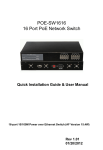
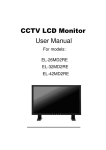
1
Cascade
Configuration Tool
Version 1.0.10
Installation and Operations Manual
00-02-0724
01-25-11
Section 40
In order to consistently bring you the highest quality, full featured products, we reserve the right to change our
specifications and designs at any time.
Please read the following information before installing.
BEFORE BEGINNING INSTALLATION OF THIS MURPHY PRODUCT:
•
Read and follow all installation instructions.
•
Please contact FW MURPHY if you have any questions.
Table of Contents
Introduction ............................................................................................................................. 1
Installation ............................................................................................................................... 1
System Requirements ..................................................................................................1
Installation Instructions .................................................................................................2
Installing USB Driver .............................................................................................................. 4
Tools Needed ...............................................................................................................4
Installation ....................................................................................................................4
Programming Mode ................................................................................................................ 6
Application GUI Overview ...................................................................................................... 7
Launching the Application ............................................................................................7
Menus and Tool Bars ...................................................................................................7
Navigating Cascade Configuration Tool .......................................................................9
Guidelines for Configuring the Cascade Configuration Tool .......................................... 10
Defining the System ...................................................................................................10
System of Operation ..................................................................................................11
Appendix A - Tables ............................................................................................................. 13
Introduction
Cascade Configuration Tool is a PC-based configuration software for the Cascade controller.
The easy-to-use interface enables you to modify the parameters of the Cascade as shown in
Table 1.
File transfer utilities for configuration and firmware upgrades are provided so that once the
configuration is set, it may be downloaded from your PC to the Cascade via a serial or USB
connection.
Installation
System Requirements
A RS485/232 to USB adapter is required for transferring the configuration from the
Configuration Tool to the Cascade.
While the Configuration software will function on any PC or laptop running Windows, it will not
perform transfers using the USB driver unless the operating system supports USB. USB
supported operating systems include Win98SE, NT, XP, Vista and Windows7.
Serial transfers using standard communication ports (COM1, COM2) should be possible on all
Windows platforms.
The Cascade Configuration Tool software and USB driver provide efficient use of your hard
drive, using only 3-5 MB of disk space after installation.
Section 40
01-25-11
00-02-0724
-1-
Installation Instructions
Follow the steps below to install the Cascade Configuration Tool software on a PC or laptop.
1. Insert the CD101 CD into your computer CD drive. The installation menu is
displayed. Click [Next] to continue.
2. You will be asked for a destination folder for the program. You can accept the
suggested directory or you can select a different directory by clicking [Browse]
and browsing to the destination folder. Once the destination folder is determined,
click [Next] to continue. (Note: click [Disk Cost…] to check disk space).
3. To check to see your available disk drive space, click [Disk Cost…]. The following
screen is displayed. When finished, click [OK]. This will return you to the previous
screen. Click [Next] to continue.
Section 40
01-25-11
00-02-0724
-2-
4. The Wizard will now install the program. This may take several minutes. The
following screen is displayed during the installation.
5. When the installation is complete, the following screen is displayed. Click [Close].
Section 40
01-25-11
00-02-0724
-3-
Installing USB Driver
Tools Needed
USB to RS485 Converter
USB Cable
Programming Cable
Cascade Controller
PC
Power Supply (9-32 V, 24mA)
Installation
To use the USB connection device to download the configuration into the Cascade controller,
you will need to use the Murphy installation kit. Follow the instructions listed below to connect
the computer and device:
Section 40
01-25-11
00-02-0724
-4-
NOTE: The installation kit provides everything needed to connect the
Cascade to your PC.
1. Connect the programming cable end with the db9 connect to the RS485 to USB
converter.
2. Connect the USB cable to the USB to RS485 converter.
3. Connect the opposite end of the programming cable to the Cascade 10 position
connector.
4. Connect the opposite end of the USB cable to the PC.
5. Connect Battery (+) to position 1 on the 15 position terminal block.
Section 40
01-25-11
00-02-0724
-5-
6. Connect Battery (-) to position 2 on the16 position terminal block.
Programming Mode
Flip dip switch number 1 to the closed position (up) on the rear of the Cascade.
This will allow the controller to power up in the programming mode. Once all programming
cables and power are connected to the Cascade, initiate power. The controller should now be
in programming mode.
The Cascade’s green LED to the right of AUTO will flash very quickly. This LED turns off briefly
while the right-hand bank of LEDs flash “on” for proper bulb verification. Once the bank of
LEDs flash and remain off, the green light to the right of AUTO will have a slower steady flash.
In the first bank of LEDs labeled “OVER SPEED”, the bottom red LED remains on. This is the
first parameter and indicates you are now in Programming Mode.
Once the program is loaded successfully, flip the number 1 dip switch to the open position and
remove power from the controller.
Section 40
01-25-11
00-02-0724
-6-
Application GUI Overview
This section provides instructions for launching the Cascade Configuration Tool, identifies the
application features that are accessible through the menu bar, and defines general navigation.
Launching the Application
To launch the application you either double-click the Cascade Configuration Tool application
icon
located on your desktop, or select “Cascade Configuration Tool Design” from the list
of programs under your “Start” menu. The following dialog box is displayed.
Menus and Tool Bars
The tool bar provides one-click access to opening an existing file and saving the currently
displayed file. These same functions are available from the “File” drop-down menu. The “File”
menu also provides the ability to print a report. (Note: The Report selection will only print a
report of the current configuration to a printer connected to the PC and will not display the
report.)
Section 40
01-25-11
00-02-0724
-7-
Selecting “Attach to Cascade” provides the ability to connect to an existing Cascade once all
cabling is connected and power is initiated on the controller. Once connected, the configuration
from the Cascade can be downloaded and viewed.
Selecting “Configurations” allows you to write to a device, read from a device, restore the initial
configuration or set to the factory defaults. The Configurations menu item is grayed out and
unavailable when not directly connected to a device.
NOTE: The PC and device must be linked in order to have access to the
Configurations menu item.
Selecting “Help” provides access to the Instruction and Operations manual, information about
the PC Configuration Tool and the User’s Manual.
Section 40
01-25-11
00-02-0724
-8-
Navigating Cascade Configuration Tool
Navigating the Cascade Configuration Tool application interface is versatile and easy. It
contains one window and it has four sections of information for each tab. Each tab contains a
similar format although not identical. See the illustration below.
Here is what each section contains:
(A)The configuration section a list of items that can be configured.
(B) The Value (*Default) section contains drop-down boxes from which the user can select a
value.
(C) The Configuration Value (Binary) section contains the binary value for what is selected in
section (B).
NOTE: This section will indicate to the user when the default value has
been altered by turning the binary values to the right red.
(D) The Help section provides context sensitive help for each of the values to be entered.
NOTE: The Help is displayed when the box is selected.
(E) This section is displayed on screens requiring additional user input.
NOTE: Sections (B) and (E) are the only sections to which the user can
make changes.
Section 40
01-25-11
00-02-0724
-9-
Guidelines for Configuring the Cascade Configuration Tool
This section provides guidelines for setting up common configuration items in Cascade
Configuration Tool.
There is a logical sequence to follow when configuring the Cascade. These sequences will be
explained in four separate topics. They are:
• Defining the System
• System of Operation
• System of Interface
Defining the System
The first step in defining the system is to gather information for setting up your analog and/or
digital devices and control outputs. For your convenience, you may want to make a checklist of
this information for entering into the Cascade Configuration Tool. Once this information has
been entered, it will be available for subsequent configuration options.
The following items from the Main Menu List allow you to define the system. Refer to the
context sensitive help contained in the product for information on field options you will be
entering.
Parameters
Below is a list of the parameters that the Cascade will ask you to define.
Parameter 1-12
1. Engine Speed
Source
2. Crank
Attempts
3. Crank Timer
4. Crank Rest
Timer
5. Start Delay
Timer
6. Stop Delay
Timer
7. Preheat
Timer
8. Extended
Preheat Timer
9. Warm-up
Timer
10. Cool-down
Timer
11. Bypass
Timer
12. Energize to
Stop Timer
Parameter 13-26
13. Aux input
Bypass Timer
14. Cranking
Abutment Delay
15. Remote Start
Signal Type
16. Low Oil
Pressure
17. High Engine
Temp.
18. Digital Input 3
(Aux Input 1)
19. Digital Input 4
(Aux input 2)
22. Fuel Relay
Control
23. Auxiliary
Output 1
24. Auxiliary
Output 2
25. Auxiliary
Output 3
26. Auxiliary
Output 4
Parameter 28-36
Parameter 37-48
28. Initial Power-up Mode
37. Overspeed Setpoint
29. Oil Pressure Crank
Disconnect Delay
30. Nominal Generator
Frequency
Enter Crank Disconnect
Freq.
31. 10’s Digit
38. Underspeed Setpoint
Parameter 48-59
Reserved
Flywheel Tooth
Count
48. 100’s Digit
21. Reserved
49. 10’s Digit
27. Reserved
50. 1’s Digit
45. Reserved
Run Speed
46. Reserved
51. 1000’s Digit
47. Reserved
52. 100’s Digit
55. Reserved
53. 10’s Digit
56. Reserved
34. 100’s Digit
54. 1’s Digit
57. Reserved
35. 10’s Digit
59. Fault Code SPN
Conversion Method
58. Reserved
32. 1’s Digit
Enter Crank Disconnect
RPM
33. 1000’s Digit
39. Underspeed
Response
40. Low Press Shutdown
Setpoint
41. Hi Eng Temp.
Shutdown Setpoint
42. Lo Batt Voltage
Setpoint
43. Hi Batt Voltage
Setpoint
44. Weak Battery
Voltage Setpoint
36. 1’s Digit
20. Reserved
60. Reserved
61-63. Reserved
NOTE: For further information on the parameters, see Appendix A - Tables in
this document.
Section 40
01-25-11
00-02-0724
- 10 -
System of Operation
The sequences to be defined for system of operation determine the day-to-day, normal
operation of your equipment. The following items from the Main Menu List allow you to define
the system of operation. Refer to the chapter titled “Main Menu List - Screen Definitions” for
information on field options you will be entering.
File
Open Configuration Item
This feature allows the user to open a saved configuration from a location on the PC.
Save Current Configuration to a File
This feature allows the user to save a configuration into a file on the PC. This will allow the use
of configuration at a later date.
Print Report
This feature prints a report of all the parameters in the configuration using the default printer of
the PC.
Exit
This closes the configuration tool.
Attach to Cascade
Connect
This allows the configuration tool to communicate to the Cascade once all the cabling is
connected and power is initiated on the controller.
Configurations
Write to Device
To download a configuration to the Cascade controller, first make sure the PC is connected to
the controller via USB to RS45 converter and the controller is in programming mode. In the
“Configurations” menu, click “Write to Device”. You will now see a text box with a message that
states “Successful Write to Device.”
After downloading the configuration, remove the USB to RS485 converter cable from the
Cascade, take the controller out of programming mode and cycle the power. The controller will
now power up with the new configuration installed.
Section 40
01-25-11
00-02-0724
- 11 -
Read from Device
To upload a configuration from the Cascade controller, first make sure the PC is connected to
the controller via USB to RS45 converter and the controller is in programming mode. Click on
“Configurations” then click “Read from Device”. After uploading the configuration, the
parameters will be shown in the configuration value row. To distinguish if the parameter I not a
default parameter, the small configuration value boxes will be red.
Restore Initial Configuration
This feature allows the user to restore the Cascade’s configuration to the configuration
software from when the initial “Read from Device” was selected. This allows the user to make
changes to a configuration originally pulled from the Cascade, then go back to view, compare,
or load the original configuration before changes were made.
Set to Factory Defaults
This feature enables the user to reset the factory defaults of the Cascade without having to
manually do so.
Help
Configurator IOM
Click this menu item to obtain an Installation and Operations Manual for the Cascade
Configuration Tool.
Cascade IOM
Click this menu item to access the Installation and Operations Manual for the Cascade. This
will open a window browser and redirect the user to the Cascade product home page on the
FW Murphy web site. Under the Literature Tab of this page, the current IOM is listed and
provided in a PDF format. This feature is only available on a PC that is connected to the
internet.
About PC Configurator Tool
This identifies the software version of the configuration tool.
Section 40
01-25-11
00-02-0724
- 12 -
Appendix A - Tables
Section 40
01-25-11
00-02-0724
- 13 -
Section 40
01-25-11
00-02-0724
- 14 -
Section 40
01-25-11
00-02-0724
- 15 -
Section 40
01-25-11
00-02-0724
- 16 -