1
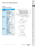
Delphi Diagnostics DS100E user manual version 7.0 Software Version 1.17.0 1. Summary 1 Summary 2 Copyright/Trademark 3 About the DS100E 4 Main functions of the DS100E tool 5 OBD 6 EOBD 7 Configuration “characteristics” 8 DS100E print Function Instructions 9 Warranty 10 Support 11 Abbreviations 12 Help Programme 13 Technical problems 14 Active Sync. 15 Install Software Update 2 2 3 3 5 7 21 27 32 38 38 38 38 39 42 44 2. Copyright/trademarks Not to be reproduced in any manner without the written consent of Delphi Corporation, Troy Michigan. Copyright protected since 2005. 3. About the DS100E - DS100E is a microcomputer-based interface for vehicle electronics. - DS100E allows troubleshooting and repair of electronic systems in vehicles. - DS100E is a user-friendly, fast and precise diagnostic tool. The system has a very comprehensive vehicle database which is regularly updated and expanded. - DS100E is Pocket PC-based software which, together with the hardware, is designed for the rugged conditions in workshops. Serial communication with system such as engine, ABS, SRS, ACC etc. - Read and delete fault codes. - Extinguish service lamps - Activate components. - Full eOBD functionality (CAN, J1850, KWP2000, and ISO9141). Basic equipment. - OBD interface with Bluetooth® connection (including 16-pin OBD connection). - Diagnostic program on SD card. - User manual. - Ruggedised Case. 3 Description of the key parts. Interface Module (VCI) with 16 pin eOBD socket. The number of the VCI, is the serial number on the bottom of the unit. Pocket PC with ruggedised case 4 DS100E Start up. To start the DS100, with a 2190B unit, press the power button located on the top right of the PDA. On the 114 the power button is located on the top right hand edge, as shown. HP2190B HP114 4. Main functions of the DS100E tool To start the diagnostic program, click on icon DS100E beside the red point. It is possible to choose between the buttons OBD, eOBD, characteristics and In connection with... 5 Definition of the buttons OBD (On-Board Diagnostics). For reading fault codes and parameters from the relevant system (engine, ABS, SRS, ACC, etc.) via the vehicle’s diagnostic system. eOBD (European On-Board Diagnostics). For reading fault codes and parameters according to the eOBD standard via the vehicle’s diagnostic system, eOBD. Applies to emission related systems such as the engine and gearbox. Settings. Entry of workshop information, language settings, hardware settings and version information. Exit Help State of battery charge 6 5. OBD Since 1994-1996, most new cars have been tted with a 16-pin diagnostic socket. According to the standard, the socket must be located within a radius of one metre from the driver’s seat, usually under or close to the dashboard. OBD (On-Board Diagnostics) is a diagnostic function built into the vehicle for reading fault codes and parameters from relevant systems (engine, ABS, SRS, ACC, etc.). To start OBD communication, click OBD in the main menu. After each menu choice there are the options “Next” (arrow to the right) and “Back” (arrow to the left). Step 1: Choose the vehicle Manufacturer, then click or Press history button to see most recent entries. Step 2: Choose model and click Red arrow . NOTE: Some vehicles support a scan function which enables all ECU’s on the vehicle to be scanned and fault codes read. 7 Step 3 Choose model year and click forward arrow. Note any instructions indicated in the message th box ( 10 digit in vin number=S) Step 4: Choose type of system. There are thirteen types of system to choose from in DS100E; see opposite. Click right arrow to advance, left arrow to go back to previous screen. 8 Ignition systems. Fuel systems. Engine. Diesel. A.B.S. Anti-lock braking system Instruments. Transmission. Immobiliser. SRS Airbag. AC (Air Conditioning). Multi-function (radio, 4WD, Chassis etc.). TCS (traction control system). Service light reset (S.L.R.) 9 Step 5: Choose engine code and click. Forward arrow. For information about the location of the engine code, click “Information”. Information. Click the information button to nd out where your engine code is located. Step 6: Choose a system and click forward arrow. 10 Step 7: Choose manual or automatic transmission and click forward arrow. Step 8: Start the diagnosis. Follow the instructions and then click “OBD”. For information about engine code location (red cursor), diagnosis socket (yellow cursor) or control unit (green cursor) click “Information”. 11 Connection to the vehicle. Select the button shown to obtain the cable type and Delphi cable part number for the vehicle. Example of BMW cable for older models. Click on return arrow, to move back to previous screen. 12 List of cable references including external power cable for items marked 1 opposite. Example of cables available. Step 9 Option 2: Reading and erasing fault codes, Real Time Data and component activation will vary with the version purchased. (Plus or Max) 13 Read the error code, click on the arrow to return to the previous screen. If you wish to print a copy of the fault code, press the print icon and follow the on-screen instructions. If the printer is not set up , go to page 32 Erase the fault codes by clicking on the dustbin Icon. 14 Click on the item to be checked and it will appear in the lower box. Scroll up and down the list with the red arrows shown. To activate a component, select it from the list and then click the red arrow. To stop the activation click on the red square. Note: Carry out these tests with the engine off. 15 Other samples of reading real time data and component activation. Activation example: 1 Select function, it will turn to a blue background. 2 Click on the red triangle, activation will commence. 3 Click on the red square to stop the activation. 16 Programming and adjustment function. The adjust function is found under real time data. Using this function you can modify idle speed and other sensor settings. See the help file for this procedure. 17 The function programmer allows you to reprogram keys on certain vehicles. Click on the question mark for assistance. Follow the help file to carry out the programming. NOTE: Follow the instructions exactly to avoid any problems. 18 Click on the box to activate the keyboard, all entries must be in upper case. Service light reset. Select “Service Light Reset” 19 Select “ Reset service.” Step 10: Service Reset. To access Service Reset, choose Service Reset in the system choice; see Step 4, then the resetting that you wish to do. There are variants of the service reset function depending upon the vehicle selected. With manual service reset, a message appears, explaining how to reset the service function. For service reset via the diagnostic socket, follow the connection instructions and then choose reset. 20 6. eOBD Note: Standard eOBD is supported on petrol vehicles from 2001 and diesel vehicles from 2003. eOBD is a protocol used throughout the European union. The main function of the system is to ensure that vehicles in use on the roads are not producing polluting levels of exhaust gases. All petrol engine vehicles sold since January 2001 must conform to this regulation. A similar code for Diesel and L.P.G. vehicles was introduced in 2004. The eOBD legislation relates only to the engine. All other parameters eg. A.C, SRS Airbag, A.B.S. etc. are controlled by the OBD protocol. The16 pin socket is standard and must be located within 1 Meter of the center of the steering wheel. The following functions are available via eOBD: Read and erase fault codes, Information, Reading live data, Oxygen sensor information, non continuous test info and control of diagnostic systems. The following information is displayed when you click on the button. 21 Control units available. All the units supporting eOBD are displayed in the list. Information. The list shows the status of each parameter. It will also show the MIL status, the number of DTC’s recorded and the standard being used. Tests available. The tests available vary with the manufacturer, those available in this example can be seen from the list below: - Lighting System. - Fuel System. - Tests on electrical components. - Catalyst. - Preheating of catalyst. - Secondary air system. - Air Conditioning - Oxygen Sensor - Heating of the oxygen sensor. - EGR Valve. Reading fault codes. Only, the permanent or intermittent eOBD error codes are displayed on the PDA. The number of the ECU, the fault code and its definition will be displayed . Permanent fault code. This is a fault code the ECU classes as a permanent fault. Intermittent fault code. This is a fault code that occurs intermittently. The ECU logs the fault and if it keeps reoccurring over a measured period of time then the ECU will change its status to a permanent fault. 22 Erasing fault codes. With this function, it is possible to erase a fault code. To remove the fault, press the dustbin icon. If the erase function fails, a message will be displayed showing the fault codes that have not been erased. . Real time data. This function allows the display of the data in real time measured by the selected ECU. To select the value to be measured in the list, Click on it with the pen. The user can select several items at the same time. To remove a value, from the lower window, click on it with the pen. 23 Freeze frame data. This function allows the display of the data in real time measured by the selected ECU. The value is illustrated along with its PID reference, its name, the measured value, its unit e.g. degrees and the manufacturers value for comparison. Use the arrows to navigate between screens. Oxygen Sensors This function enables you to obtain the values of each lambda. Probe. The EOBD functions with two probes, per and post catalyst, for the control of pollution in the exhaust gas. Each probe can be selected and controlled independently. On some vehicles the oxygen sensor information can be found under “non-continuous tests” 24 Non continuous tests. The values are read automatically and they indicate the TID and the CID values which are defined by the manufacturer. The column "Result" indicates if the test is OK or not. The actual values along with the min and max values are indicated in the display. Vehicles using can protocol also display oxygen sensor info. in this section. Control of system. The list of the tests is accessible through the ECU. The tests are displayed with a description, TID reference and an actual value. 25 Vehicle Information. This function can display three values per ECU, as indicated below: --VIN, Chassis number --CIN, Calibration Identification number --CVN, Calibration verification number 26 7. Configuration Characteristics. This screen gives you access to the main functions of the tool. Garage Information. 27 Language Selection. Installation and configuration information. Under this function you can configure the wireless interface. Select "Bluetooth" for linking the interface between VCI and pocket PC. When the program is updated, you will have to update the software in the interface, click on the update firmware button to update firmware, this action takes approximately 10 minutes. 28 Bluetooth Configuration of the wireless interface. Connect the interface to a vehicle then click on the magnifying glass. The PDA will seek the interface and the address will appear under Bluetooth address, click on "stop" then click on the line to reveal the number in the box To then register the electronic key using the keyboard (in upper case) Example of Hardware key code VCI : 31126 1.12 HW : LIPTJUPWQOOW SW MAX: BHPRVJPBGJOM Then click on the return arrow which will validate the hardware key. Follow the on-screen instructions if you experience any difficulties. Bluetooth switch is accessed via the front screen Click Start/settings/connections/Bluetooth/off/on Then O.K.and exit 29 To Update the firmware. This function updates the communications protocols between the PDA and VCI.It must be carried out with each update. Power up the VCI by connecting it to a vehicle, or its mains charger, then click on the button to update firmware. Attention: The update can take up to 15 minutes to complete, during this time the PDA and VCI must be no greater than 15 Meters apart. 30 Software installation and key activation. This function makes it possible to change DS100E base to Plus or Max. Click on the software button "Installation" to obtain the following screen: VCI : 31126 1.12 HW :: LIPTJUPWQOOW SW MAX: BHPRVJPBGJOM Type code (SW, EMS, SWMax, etc.) from the reference number supplied on the label to activate the various functions. Use the keyboard in upper case, then click on "Add key". Note: After updates and in the event of components being changed, the software codes will have to be entered again. 31 8 DS100E Print Function Instructions NOTE: Before setting PDA print parameters, set up printer following printer manufacturer’s installation instructions. Insert Bluetooth dongle into printer as shown Click on print icon located on the “read fault code” screen. This feature is available in either OBD or EOBD diagnostic programs. Fill in relevant information and press print icon 32 These parameters are pre-set, click O.K. Tick box “always use the selected device” then Select Deskjet 6940 series 33 The document will then print, The printing process must be completed before you can save any information. If you wish to save the information follow the instructions below If you wish to save information, click the save icon 34 Name the file and folder, select location, click save Progress of saved (printing) file will then be shown When complete click red arrow 35 The PDA is now back in diagnosis mode If you wish to view a saved file, it will be stored in PDF format in “my documents” If you wish to print a saved file, you can do this by linking the PDA to a desktop or laptop via active sync. “My Documents” file listing. 36 The size of the document can be adjusted using the keys shown Please remember that you can only print a saved file by linking the PDA to a desktop or laptop PC via active sync. Information on the system: Serial number of the VCI, Version of the software and firmware. Support Information: Telephone number Fax. Number E-mail and Internet site . 37 9. Warranty. Warranty period is 12 months from the date of delivery. The warranty does not cover shipping and transport costs. In the event of a claim under the warranty, the goods must be packaged in such a way that damage in transit is avoided and must be clearly marked with the fault symptom that has led to the claim. Further, the warranty does not include liability for incorrect handling, incorrect connection or consequential damage caused by circumstances outside our control. 10. Support For support contact your local distributor. 11. Abbreviations ABS Antilock Braking System AC Air Conditioning. AT Automatic transmission. DTC Diagnostic Trouble Code. ECU Electronic Control Unit. EGR Exhaust Gas Recirculation. EMS Engine Management System. eOBD European On-Board Diagnostic. EVAP Evaporative system. MIL Malfunction Indication Lamp. PID Parameter ID. SRS Supplementary Restraint System. TCS Traction Control System. TID Test ID. 12. Help Program. To obtain the contents, click on the help button (?). From the index select the information that you require. 38 13 Technical Problems. If you receive this message opposite, Check the Bluetooth configuration between the interface and pocket PC. Check on the screen that the Bluetooth configuration and address is correct. If not repeat the Bluetooth configuration outlined above. Also check that the battery is correctly charged. To carry out a software reset press pen into the hole in the base of the unit as shown opposite. Check that the battery is charged. 39 Hard Reset 2190B 1 Press and hold down the Power, Calendar and Messaging buttons. 2 While holding down these buttons, use the stylus to lightly press the Reset button on the bottom of the iPAQ Pocket PC for about two seconds. 3 When the Pocket PC screen begins to fade, release the Power, Calendar and Messaging buttons first, and then remove the stylus from the Reset button. NOTE: If you simultaneously push and hold the Power, Calendar, and messaging buttons for more than two seconds, the battery disconnects. To restart the device, either plug the device into the AC Adapter or press the Reset button again.After performing a hard reset, you may need to reinstall applications stored in iPAQ File Store to restore shortcuts and full functionality. Hard Reset 114 Press and hold the start button (1), the O.K. button (2) and record button (3) Using the probe press and release the reset button (4) Then release the start, O.K. and record button. . If the operation has been successfully performed then “CLEAN BOOT” will appear in the bottom left corner of the screen. If “CLEAN BOOT” is not visible then repeat the process above until it is. 40 To re-install the software of the DS100, remove card and then re-insert it back into PC. CAUTION: the codes will have to be re-registered in pocket PC. Make sure that the small switch on your SD card is set to “ON”, as referred to in the picture 41 14. ACTIVE SYNC. Initial installation. Install Microsoft “Activesync” see below for link if needed http://www.microsoft.com/windowsmobile/downloads/activesync38.mspx Copying the files and program to the PDA Once you have installed the software loaded, plug the PDA in to the cable then to the PC. You will then be presented with the ActiveSync software. 42 This will then activate the setup partnership option. Click “Guest Partnership” and click “Next” on the setup screen. You will now be shown the PDA is connected but NOT synchronized. 43 15. Install DS100E software update. Now install the DS100E software. Run the “Delphi DS100E Install 1_4_0.exe” file by double clicking on the file wherever you have stored it (Normally supplied on CD). N.B. You have to have the SD card plugged into the PDA. Select DS100E, double click Select update you require, double click 44 The Delphi Updater will then extract Select “pocket PC with active sync”, then click install 45 Status bar will show installation progress. Click OK then check your PDA for any additional info, then click Exit. This completes the installation procedure, you now need to connect to Bluetooth, complete a firmware download and insert hardware and software keys, see relevant section in user guide. 46 Keep a note of your activation codes here HW Key……………………… SW Key……………………….. Delphi Corporation © 2009. All Rights Reserved www.delphi.com 47