1
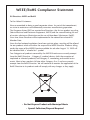
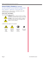
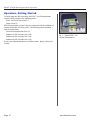
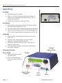
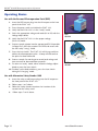
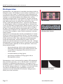
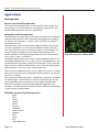
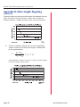
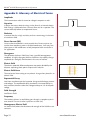
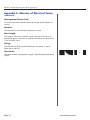
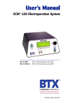
User’s Manual
ECM® 399 Electroporation System
45-0050
45-0050INT
ECM® 399 Electroporator only (110V)
ECM® 399 Electroporator only (220V)
Publication 5501-004-REV-E
WEEE/RoHS Compliance Statement
EU Directives WEEE and RoHS
To Our Valued Customers:
We are committed to being a good corporate citizen. As part of that commitment,
we strive to maintain an environmentally conscious manufacturing operation.
The European Union (EU) has enacted two Directives, the first on product recycling
(Waste Electrical and Electronic Equipment, WEEE) and the second limiting the use
of certain substances (Restriction on the use of Hazardous Substances, RoHS).
Over time, these Directives will be implemented in the national laws of each EU
Member State.
Once the final national regulations have been put into place, recycling will be offered
for our products which are within the scope of the WEEE Directive. Products falling
under the scope of the WEEE Directive available for sale after August 13, 2005 will
be identified with a “wheelie bin” symbol.
Two Categories of products covered by the WEEE Directive are currently exempt
from the RoHS Directive – Category 8, medical devices (with the exception of
implanted or infected products) and Category 9, monitoring and control instruments. Most of our products fall into either Category 8 or 9 and are currently
exempt from the RoHS Directive. We will continue to monitor the application of the
RoHS Directive to its products and will comply with any changes as they apply.
• Do Not Dispose Product with Municipal Waste
• Special Collection/Disposal Required
ECM ® 399 Electroporation System
Table of Contents
General Information:
Serial Number ................................................................2
Calibration ......................................................................2
Warranty ....................................................................2-3
Service ........................................................................3-4
Repair Facilities and Parts ..............................................4
General Safety Summary..............................................5-6
Electrical & Technical Specifications ..............................7
General Specifications......................................................8
Introduction:
ECM® 399 Features ........................................................9
Operation: Getting Started ............................................10
Quick Start:
Connecting ..................................................................11
Initializing......................................................................11
Instrument Controls................................................11-13
Operating Basics ............................................................14
Electroporation ..............................................................15
Applications:
Electroporation........................................................16-17
Appendix A: Optimization Strategies............................18
Appendix B: Pulse Length Targeting ......................19-20
Appendix C: Electrical Troubleshooting ........................21
Appendix D: Experimental Troubleshooting ................22
Appendix E: Glossary of Electrical Terms ..............23-24
Appendix F: Glossary of Biological &
Technical Terms ..................................25-26
Appendix G: Recommended Reading............................27
Appendix H: Accessories and Replacement Parts ......28
Appendix I: General Care and Cleaning ......................28
Page 1
www.btxonline.com
ECM ® 399 Electroporation System
General Information
Serial Number
The serial number for the ECM® 399 is located on the rear of the
instrument case. All inquiries concerning these products should refer
to the serial numbers on the units.
Calibration
There is no calibration required for the ECM® 399.
Warranty
BTX - Harvard Apparatus warranties the ECM® 399 for a period of two
years from the date of purchase. At its option, BTX – Harvard
Apparatus will repair or replace the unit if it is found to be defective as
to workmanship or materials. This warranty does not extend to any
instrumentation which has been (a) subjected to misuse, neglect,
accident or abuse, (b) repaired or altered by anyone other than
BTX - HARVARD APPARATUS without BTX - HARVARD APPARATUS’
express and prior approval, (c) used in violation of instructions furnished by BTX - HARVARD APPARATUS. This warranty extends only
to the original customer purchaser.
Failure to use the Enhancer 3000 High Voltage probe to connect a
BTX Generator to an external digital oscilloscope for monitoring will
result in voiding your warranty; connecting directly to the external
monitoring equipment or modified monitoring setup will damage the
Generator.
IN NO EVENT SHALL BTX - HARVARD APPARATUS BE LIABLE FOR
INCIDENTAL OR CONSEQUENTIAL DAMAGES. Some states do not
allow exclusion or limitation of incidental or consequential damages so
the above limitation or exclusion may not apply to you. THERE ARE
NO IMPLIED WARRANTIES OF MERCHANTABILITY, OR FITNESS
FOR A PARTICULAR USE, OR OF ANY OTHER NATURE. Some states
do not allow this limitation on an implied warranty, so the above
limitation may not apply to you.
Without limiting the generality of the foregoing, BTX - HARVARD
APPARATUS shall not be liable for any claims of any kind whatsoever,
as to the equipment delivered or for non-delivery of equipment, and
whether or not based on negligence.
Warranty is void if the ECM® 399 is changed in any way from its
original factory design or if repairs are attempted without written
authorization by BTX - HARVARD APPARATUS.
Warranty is void if parts, connections or cell fusion chambers not
manufactured by BTX - HARVARD APPARATUS are used with the
ECM® 399.
Warranty is void if the Enhancer 3000 High Voltage probe is not used
when connecting BTX Generators to external monitoring digital scope;
as connecting directly to the external monitoring equipment will
damage the Generator.
Page 2
www.btxonline.com
ECM ® 399 Electroporation System
General Information
(Continued)
If a defect arises within the warranty period, promptly contact
BTX – Harvard Apparatus, 84 October Hill Road, Building 7, Holliston,
Massachusetts, USA 01746-1388 using our toll free number
1-800-272-2775 (US Only) or 508-893-8999
(E-mail: [email protected]). Goods will not be
accepted for return unless an RMA (Returned Materials Authorization)
number has been issued by our customer service department. The
customer is responsible for shipping charges. Please allow a
reasonable period of time for completion of repairs, replacement and
return. If the unit is replaced, the replacement unit is covered only for
the remainder of the original warranty period dating from the
purchase of the original device.
This warranty gives you specific rights, and you may also have other
rights, which vary from state to state.
Service
All service under the warranty will be made at the BTX - HARVARD
APPARATUS, Holliston, Massachusetts facilities or an authorized
service site. Owner will ship instrument prepaid to Holliston,
Massachusetts, USA or the service site. BTX - HARVARD APPARATUS
will return the instrument after servicing, freight prepaid to owner’s
address.
Obtaining Service:
Service During Warranty
1. Write or call the BTX - HARVARD APPARATUS Customer
Support Group and describe the nature of the problem.
2. Carry out minor adjustments or tests as suggested by
BTX - HARVARD APPARATUS.
3. If proper performance is not obtained, BTX - HARVARD
APPARATUS will notify you to ship the instrument, prepaid,
to its Service Department.The instrument will be repaired
and returned at no charge for all customers in the
continental United States.
Customers outside of the continental United States who have
purchased our equipment from distributors should contact the
distributor. If you have purchased your equipment from us, you
should contact us directly. We will repair at no charge, but will not
pay for shipment, documentation, etc. These charges will be billed
at cost.
Note: Under no condition should the instrument or accessories be
returned without prior approval from BTX - HARVARD APPARATUS. An
RMA (Returned Materials Authorization) number must be obtained.
Page 3
www.btxonline.com
ECM ® 399 Electroporation System
General Information (continued)
Out-Of-Warranty Service
Proceed exactly as for Warranty Service, above. If our Service
Department can assist you by phone or correspondence, we will be
glad to, at no charge.
Repair service will be billed on the basis of labor and materials. A
complete statement of time spent and materials used will be supplied.
Shipment to BTX - HARVARD APPARATUS should be prepaid. Your
bill will include return shipment freight charges.
Disassembly by the user is prohibited. Service should only be carried out
by experienced BTX - HARVARD APPARATUS technicians.
Repair Facilities and Parts
BTX - Harvard Apparatus stocks replacement and repair parts. When
ordering, please describe parts as completely as possible, preferably
using our part numbers. If practical, enclose a sample or drawing. We
offer complete reconditioning service.
Page 4
www.btxonline.com
ECM ® 399 Electroporation System
General Safety Summary
Review the following safety precautions to avoid injury and prevent
damage to this product or any products connected to it. To avoid
potential hazards, use this product only as specified.
Only qualified personnel should perform service procedures.
To Avoid Fire or Personal Injury
USE PROPER POWER CORD
Use only the power cord specified for this product and certified for
the country of use.
CONNECT AND DISCONNECT PROPERLY
Do not connect or disconnect probes or test leads while they are
connected to a power source.
GROUND THE PRODUCT
This product is grounded through the grounding conductor of the
power cord. To avoid electric shock, the grounding conductor must
be connected to earth ground. Before making connections to the
output terminals of the product, ensure that the product is properly
grounded.
OBSERVE ALL TERMINAL RATINGS
To avoid fire or shock hazard, observe all ratings and markings on the
product. Consult the product manual for further ratings information
before making connections to the product.
DO NOT OPERATE WITHOUT COVERS
Do not operate this product with covers or panels removed.
Use Proper Fuse. Use only the fuse type and rating specified for this
product.
AVOID EXPOSURE TO CIRCUITRY
Do not touch exposed connections and components when power is
present.
DO NOT OPERATE IN LOW IMPEDANCE
Sample: Load or Sample
If the electroporation samples have impedance of less than 20 Ω in LV
and 40 Ω in HV, the samples may arc and result in sample loss and
potential damage to unit.
DO NOT OPERATE WITH SUSPECTED FAILURES
If you suspect there is damage to this product, have it inspected by
qualified service personnel.
PROVIDE PROPER VENTILATION
Refer to installation instructions for details on installing the product to
ensure proper ventilation.
DO NOT OPERATE IN WET/DAMP CONDITIONS
Page 5
www.btxonline.com
ECM ® 399 Electroporation System
General Safety Summary
(Continued)
DO NOT OPERATE IN AN EXPLOSIVE ATMOSPHERE
KEEP PRODUCT SURFACES CLEAN AND DRY
Should you have any safety concerns, immediately contact BTX
Technical Support (1-800-597-0580)
Safety Terms and Symbols:
Terms that appear in this manual:
WARNING. Warning statements identify conditions
or practices that could result in injury or loss of life.
CAUTION. Caution statements identify conditions
or practices that could result in damage to these
products or other property.
Symbols that may appear on the products:
Page 6
Danger
Attention
Protective
Functional
High
Voltage
Refer to
Manual
(Earth)
Terminal
Ground
www.btxonline.com
ECM ® 399 Electroporation System
Electrical & Technical Specifications
Standard Capabilities:
Display
Power Source
Voltage
Power
Fusing
Type: 16-character liquid
crystal LCD backlit
100 to 240 Vac, 50 to 60 Hz,
CAT I
< 100 W peak
2.5 A, T rating 250 V
Environmental Characteristics:
Intended Use
Indoor use only
Operating Temperature
10ºC to 40ºC
Cooling
Convection through metal
case
Relative Humidity
60%
Altitude
2,000 m (operating)
Mechanical Characteristics:
Maximum Voltage
Output: 2,500 Volts Peak
Maximum Pulse Length
125 ms @ 500 Volts peak or
5 ms @ 2,500 Volts peak
Pollution Degree 2
(Not to be operated in
conductive pollutants
atmosphere)
Page 7
www.btxonline.com
ECM ® 399 Electroporation System
General Specifications
General Specifications, Certifications & Compliances EMC
Overvoltage Category:
CAT III: Products in this Category: Distribution-level mains, fixed
installation.
CAT II: Local-level mains, applications, portable equipment.
CAT I: Signal levels in special equipment or parts of equipment,
telecommunications, electronics.
EMC
Meets requirements of Directive 89/336/EEC for
Electromagnetic Compatibility (EC) and Low-Voltage
Directive 73/23/EEC for Product Safety. Compliance was
demonstrated to the following specifications as listed in
the Official Journal of the European Communities:
EN 50081-1 Emissions
EN 55011 Class B Radiated and Conducted Emissions
EN 55082-1 Immunity
IEC 10004-2 Electrostatic Discharge Immunity
IEC 10004-3 RF Electromagnetic Field Immunity
IEC 10004-4 Electrical Fast Transient/Burst Immunity
Safety Low Voltage Directive 73/23/EEC
EN 61010-1 Safety requirements for electrical
equipment for measurement, control and laboratory use.
BTX INSTRUMENTS ARE DESIGNED FOR IN VITRO AND IN VIVO
ANIMAL AND PLANT APPLICATIONS ONLY, AND ARE NOT FOR
HUMAN USE
Page 8
www.btxonline.com
ECM ® 399 Electroporation System
Introduction
The ECM® 399 is an electroporation system specifically designed to
produce the precise field strengths and pulse lengths required for the
transformation of gram -bacteria yeast and limited transfection of
mammalian cells.
ECM® 399 features include:
•
Sophisticated digital design
•
High resolution, easy to read Liquid Crystal Display
providing readout of: status, voltage mode, setpoint and
actual parameters
•
Voltage range of 2 to 500 V with 2V resolution in LV mode
with a 150 ohm resistance and 1050 µF capacitance
delivering a pulse length of approximately 5 to 55 msec
using a low impedance electroporation buffer depending on
volume and temperature
•
Voltage range of 10 to 2500 V with 10 V resolution in HV
mode with a 150 ohm resistor and a 36 µF capacitor
delivering a pulse length of approximately 5 msec using a
high impedance electroporation buffer
•
Easy three step experimental approach: simply initialize
instrument, dial in voltage and mode with the voltage
adjust knob, and deliver electroporation pulse by pressing
the start switch
•
Dual monitoring and display of peak output voltage and
time constant to ±1 percent
Page 9
www.btxonline.com
ECM ® 399 Electroporation System
Operation: Getting Started
Carefully open the box containing the ECM® 399 Electroporation
System. Verify receipt of the following items:
ECM® 399 Pulse Generator (1)
Power Cord (1)
BTX Electroporation Systems may be customized with the addition of
various electrodes and accessories. The following items complete a
typical system order:
Personal Electroporation Pack (1)
Model 610 BTX Cuvettes Plus (10)
Model 620 BTX Cuvettes Plus (10)
Fig 1 - Typical ECM® 399
System Components
Model 640 BTX Cuvettes Plus (10)
If you have ordered alternative or different items, please verify their
receipt.
Page 10
www.btxonline.com
ECM ® 399 Electroporation System
Quick Start
Installing
1. Install on Bench or work table
2. Allow 1 to 2 inches of clearance for proper cooling. It is
normal for the instrument to be slightly warmer than its
operating environment.
3. Choose and outlet that is readily accessible.
Connecting
1. Insert female end of power cord into male power interface
on the back panel of the ECM® 399.
2. Plug male end of power cord into appropriate electrical outlet.
3. Insert male banana plugs of the Personal Electroporation Pack
(PEP™) into HV output located on front panel of the ECM® 399.
Initializing
1. Push the power switch located on the front panel of the
ECM® 399.
2. The ECM® 399 will go through a series of self-test
algorithms to test generator functionality.
3. The display will flash “BTX ECM® 399 V1.04” prior to
attaining a ready status.
4. The first time the instrument is initialized, the display will
then read “2500V HV”
Voltage
Adjust Knob
Instrument Controls
Power Switch
Display
1. Switch located on the lower
right front panel.
2. Press once to initialize the
ECM® 399 and once more to
turn off.
High Voltage
Output
Page 11
Start
Switch
Power
www.btxonline.com
ECM ® 399 Electroporation System
Quick Start
(Continued)
Display
The ECM® 399 display will show operational status, voltage mode, and
set voltage before delivery of an electroporation pulse. The display will
read the peak output voltage delivered and the time constant following
the delivery of a pulse.
Status
Ready
Operational and ready to set voltage or deliver a pulse.
Charging
Charging capacitor to the preset voltage level.
Pulsing
Delivering a voltage pulse.
Feedback
Displays peak voltage and time constant.
Sequence Aborted
Aborted delivery of a pulse at the user’s request.
SCR Failure
Has not detected an output pulse during the pulsing operation. A
short in the electrode could be the cause. This condition can only
be reset by turning the power off.
Charge Failure
Failure to charge capacitors properly. Pressing the start switch
resets this message.
Setpoint too Low
User has entered setpoint outside of normal operating
specifications.
Mode
The ECM® 399 will display HV for the high voltage mode and LV for
low voltage mode.
Set Voltage
The ECM® 399 will display set voltage in 2 volt increments in LV
mode, from 2 to 500 V and in 10 volt increments in HV mode from
10 to 2500 V.
Page 12
www.btxonline.com
ECM ® 399 Electroporation System
Quick Start
(Continued)
Actual Parameter Display
The ECM® 399 will display the peak discharge voltage (Vp) in V and
the time constant (t) in msec. It is normal for the measured voltage to
be slightly different than the setpoint. The voltage difference is due to
internal resistance and fluctuates with electrical load variations (buffer
resistivity).
Voltage Adjust Knob
The ECM® 399 Voltage Adjust Knob adjusts the voltage from 2 to 500
V in the LV mode in 2 volt increments and from 10 to 2500 V in the
HV mode in 10 volt increments. In the LV mode, increasing of the
voltage setpoint past 500 V will result in a switch to the HV mode. The
generator will emit a “beep” signaling a change from the LV mode to
the HV mode. The voltage will then readjust to 0 volts, then continue
up to 2500 V. In the HV mode, decreasing the voltage setpoint past 0
volts will result in an automatic switch to the LV mode, accompanied
by a “beep”. The voltage will then readjust to 500 V. Following the
delivery of a pulse, rotate the Voltage Adjust Knob to return to the
ready mode. If the voltage adjust knob is set between detentes
(notches), the generator may cycle through the actual parameter
display following the delivery of a pulse, as if the knob were rotated as
above. The voltage adjust knob is speed sensitive. A quick rotation of
the knob increases the rate of change of any setpoint.
Note: There are no other steps necessary to change the voltage
mode other than adjustment of the Voltage Adjust Knob.
Start Switch
The green Start Switch is activated in the “ready” mode to deliver the
electroporation pulse. Once the start switch is activated, the generator
will “settle” by bleeding off the capacitors to the preset voltage, prior
to delivering the pulse. The maximum settling time is 6 seconds. A
pulse sequence may be aborted by pressing the start switch a second
time, before delivery of the pulse. Following the delivery of a pulse,
press the start switch once to return to the “ready” mode.
•
Actual voltage delivered under load will be lower than the
set voltage, typically by 1 to 15 %
•
Voltage adjust knob controls set voltage AND voltage mode.
There is NO separate voltage mode switch!
Page 13
www.btxonline.com
ECM ® 399 Electroporation System
Operating Basics
Use with the Personal Electroporation Pack (PEP)
1. Insert the PEP banana plugs into the HV output on the front
panel of the ECM® 399.
2. Press the power switch to initialize the ECM® 399.
3. Verify that the ECM® 399 is in the “ready” mode.
4. Dial in the appropriate voltage and mode (LV or HV) with the
Voltage Adjust Knob.
PEP
45-0212
5. Verify that the ECM® 399 is in the proper voltage
(HV or LV) mode.
6. Prepare sample, pipette into the appropriate BTX Disposable
Cuvettes Plus, place the cuvette in the PEP and secure with
the PEP safety “swing” shield.
7. Press the Start Switch. The ECM® 399 will charge and then
deliver the electroporation pulse. A beep will indicate that
the pulse has been delivered.
8. Process sample. Do not forget to record peak voltage and
time constant for documentation purposes.
9. To return to “ready” mode, either rotate the Voltage Adjust
Knob or press the Start Switch.
630B
45-0207
10. To abort a pulse before delivery, press the Start Switch
during the “charging” mode.
Use with Alternative Safety Stands 630B
1. Insert the safety stand banana plugs into the HV output on
the front panel of the ECM® 399.
2. Follow steps 2 to 5 above.
3. Follow the Safety Stand instructions for insertion of the
cuvette into the safety stand.
4.
Page 14
Follow steps 7 to 10 above.
www.btxonline.com
ECM ® 399 Electroporation System
Electroporation
Electroporation is the application of controlled, pulsed electric fields to
biological systems. If the biological system contains a lipid bilayer, such
as is the case if the system is a suspension of cells or liposomes, the
pulsed electric field may overcome the field potential of the lipid bilayer,
resulting in a reversible breakdown of the bilayer and a resulting
formation of temporal pores in the membrane. The pores formed are
of the order of 40 to 120 nm. Most pores reseal within a few seconds,
after allowing the transfer of materials into and out of the cells.
During a typical electroporation process, target cells and molecules
are mixed together. When an electroporation pulse is delivered, the
result is the formation of temporal pores. Before the pores reseal, the
target molecules are observed to enter the cells. Upon resealing of
the pores, the molecules become incorporated within the cell. The
eventual target site depends on the application; for example, molecules
can remain in the cytoplasm, interact with the membrane, and move
into the nucleus.
Pore Formation
Electroporation Process
Applications for electroporation include permeabilization of virtually
all cells to a wide variety of molecules and ions. The most common
applications for electroporation are the transformation or transfection
of cells with DNA or RNA. Other applications for electroporation
include electroactivation, electroinsertion of proteins into cell
membranes and electroextraction of molecules from cells. Although
electroporation has mainly been used as a research tool, recent work
has demonstrated its potential for clinical applications. Some areas
being explored include:
•
electrochemotherapy which involves electroporation for
delivering chemotherapeutic agents directly to tumor cells
•
encapsulation of drugs/genes into cells for their use as
carrier systems
•
transdermal delivery of drugs/genes
•
gene therapy and delivery of drugs/genes with an
electroporation catheter.
Electroporation can be characterized by waveform. BTX exponential
decay waveform generators, such as the BTX ECM® 399 and ECM®
630 deliver an exponentially decaying pulse. The length of such a
discharge waveform is commonly characterized by the time required
for the initial voltage to decay to 1/e (roughly 1/3) of the initial value.
To achieve a desired pulse length, appropriate resistance and
capacitance must be selected on the instrument. Voltage may be
directly set on the instrument.
Page 15
Exponential Decay Wave
www.btxonline.com
ECM ® 399 Electroporation System
Applications
Electroporation
Bacteria and Yeast Electroporation
The most common application is transformation. Field strength and
pulse length are critical parameters for reporting, optimization, and
troubleshooting bacterial and yeast applications.
Mammalian Cell Electroporation
Electroporation has been used successfully to introduce many different
molecule types into cells. Most commonly, electroporation is used for
the process of transfection, in which nucleic acid (DNA and RNA), is
introduced into cells.
Electroporation can be used to deliver oligonucleotides into cells for
anti-sense applications. It can be used to deliver proteins into cells,
even large enzymes such as restriction enzymes, and antibodies, for
various purposes. Peptides have also been electroincorporated.
Smaller molecules have been incorporated into cells and liposomes,
such as dyes, sugars, and dNTP’S.
High GFP expression in Mouse PE501
Electroporation has been used to study cellular activation processes, by
electropermeabilizing cells to Ca2+, Mg2+, and Na+. Electroporation is also
used to electroinsert proteins into the cell membrane. Finally, electroporation has been used to introduce drugs, such as the chemotherapeutic
agent bleomycin, into cancer cells, in vitro and in vivo.
The use of low impedance buffers such as PBS may result in a voltage
drop so that the actual peak voltage delivered to samples may be less
than the set voltage.
With exponential decay generators, monitoring is necessary to identify
the pulse length, or time constant, since this parameter may be very
much dependent on the impedance of the sample (sample load).
When using complex and custom electroporation applicators and
chambers, the electroporation waveform may be altered and monitoring
is again strongly recommended.
Molecules Introduced by Electroporation
•
•
•
•
•
•
•
•
•
•
•
•
•
Page 16
DNA
RNA
siRNA
miRNA
dNTPS
Enzymes
Antibodies
Other Proteins
Peptides
Dyes
Sugars
Ions
Other Molecules
www.btxonline.com
ECM ® 399 Electroporation System
Applications
(Continued)
Plant Protoplast Electroporation
Electroporation has been used to introduce molecules into plant
protoplasts, pollen, and most recently, direct transfer into plant tissue
(in vivo).
Page 17
www.btxonline.com
ECM ® 399 Electroporation System
Appendix A: Optimization Strategies
General
The success of electro cell manipulation (ECM) lies in selecting
appropriate ECM systems capable of delivering the pulses suitable for
the cell being electromanipulated. One, or several pulses of the
appropriate field strength, pulse length, and wave shape may be
required for this purpose. (Depending on the generator selected.)
The key to success with electroporation-based technologies involves a
proper combination of biological, physical, chemical, and pulse
parameters. In general, cells must be in mid-logarithmic growth for
optimal electroporation. Various temperature regimens have been
described. It has been shown that a variety of chemical techniques
may increase electroporation efficiencies, including addition of EDTA,
DMSO, intracellular salts, and serum before or after the pulse.
Optimizing protocols abound. Analysis of these optimization regimens
has lead to proposals of universal protocols, involving very limited
optimization over a narrow range.
Electroporation
1. Vary the voltage in order to vary the field strength kv/cm,
keeping other parameters constant. Assay sample for both
viability and endpoint. Plot the field strength versus both
viability and endpoint and extrapolate the optimal field
strength (voltage divided by gap size) and voltage.
2. Vary the capacitance/resistance/sample volume in order to
vary the pulse length (time constant) for exponential decay
instruments. Directly vary square wave instrument pulse
length. Assay sample for both viability and endpoint. Plot the
pulse length versus both viability and endpoint and
extrapolate the optimal pulse length/parameters.
3. For multiple pulsing systems/protocols, vary the number of
pulses at the optimal field strength kv/cm and pulse length.
Assay sample for both viability and endpoint. Plot the
number of pulses versus both viability and endpoint, and
extrapolate the optimal number of pulses.
Page 18
www.btxonline.com
ECM ® 399 Electroporation System
Appendix B: Pulse Length Targeting
Choosing A Volume To Obtain A Predetermined Pulse Length For
The ECM® 399 or ECM® 395
Purpose
Derive pulse length curves for the ECM® 399 so the user can choose
a volume in order to meet a particular pulse length requirement. This
Application Note is useful when the researcher wants to reproduce a
protocol with a specific pulse length. The 2-step process illustrated
below allows the researcher to choose a volume which will provide
the desired pulse length.
Definition of Terms
Rs = Sample or chamber resistance.
R SYS = Internal resistance of the ECM® 399 or 395.
CSYS = Internal capacitance of the ECM® 399 or 395.
T = Time constant or pulse length delivered to sample.
Tools or Parts Needed
Any electrode, any media, ECM® 399 or 395, and an optional
Enhancer 3000®.
Comments
This Application Note is provided so the user can create his/her own
plots.
Application
1.
Find the resistance of the sample. A quick and easy way
to do this is by pulsing the sample once and measuring
the pulse length. The resistance of the sample can be
calculated with the following equation:
Rs =
Page 19
R
T
SYS*
(R
C
)-T
SYS* SYS
www.btxonline.com
ECM ® 399 Electroporation System
Appendix B: Pulse Length Targeting
(Continued)
The pulse length may be measured by either the feedback from the
ECM® 399 or by using the Enhancer® 3000. If this is done for
different volumes, a sample resistance curve can be constructed.
2.
Choose an adequate volume and use the corresponding
sample resistance to find the pulse length in milliseconds
by the equation below.
T=
Rs * Rsys
Rs + Rsys
* Csys * 10
-3
Using different sample resistances a plot of pulse length
for each volume can be made.
Page 20
www.btxonline.com
ECM ® 399 Electroporation System
Appendix C: Electrical Troubleshooting
Instrument does not power up:
Verify that the power cord is fully inserted in the instrument and in the
wall outlet. Verify that the fuse is not blown. Disconnect power cord
from the instrument before removing the fuse holder. Replace the
fuse, if necessary, with same rated fuse as indicated on back panel.
The ECM® 399 is constantly monitoring the parameters of some of its
internal circuitry. In the case of a malfunction, one of the following
messages will appear on the display. Note the instructions on the
following page.
SCR Failure:
The ECM® 399 has not detected an output pulse during the pulsing
operation. A short in the electrode could be the cause. Unplug the
generator for 90 seconds then reset by cycling the power and pulsing
one more time. If the same message reappears, call BTX Customer
Service.
Charge Failure:
The ECM® 399 has detected a failure to charge its capacitors properly.
Press the start switch to reset this message. A very low line voltage or
a brownout is likely the cause. Verify that the circuit powering the
ECM® 399 is adequately rated. If the message persists, call BTX
Customer Service.
Setpoint too Low:
The user has entered a setpoint that is outside of normal operating
specifications. Increase voltage setting.
Page 21
www.btxonline.com
ECM ® 399 Electroporation System
Appendix D: Experimental
Troubleshooting
Arcing
Verify electrical component functionality. Verify properties of cell
sample (do cells need to be washed? Is the buffer appropriate for
application?). Verify properties of transfectant/molecule (Is the DNA
well purified?) Try reducing the voltage or increase sample volume
until arcing is no longer a problem.
Low (or no) transfection efficiency, or incorporation
Verify physical, biological, and chemical parameters. Verify delivery of
the pulse and pulse parameters. Is the voltage correct? Chamber gap?
Pulse length or appropriate instrument settings? Number of pulses? If
so, follow Optimization Guidelines outlined in Appendix A.
Low viability
Verify physical, biological, and chemical parameters. Are the voltage,
chamber gap, pulse length (time constant), pulse number and other
instrument settings correct? If so, reduce voltage, pulse length, or
number of pulses and re-optimize protocol to improve viability as
outlined in Appendix A.
Page 22
www.btxonline.com
ECM ® 399 Electroporation System
Appendix E: Glossary of Electrical Terms
Amplitude
The instantaneous value of current or voltage in amperes or volts.
Capacitor
A device that stores electric energy in the form of an internal electric
field. Energy is delivered when a current flows out of a capacitor. The
current normally follows an exponential curve.
Dielectric
A material that has a high resistivity and can store energy in the form
of an electric field.
Direct Current (DC)
Current whose amplitude is constant with time. Direct currents are
used to form temporary pores in bi-lipid membranes. Cells may fuse
when pores in the membranes of two juxtaposed cells reseal after a
DC application.
Divergence
The deviation of electric field lines from a parallel homogeneous
condition. A highly divergent field has field lines that rapidly change
amplitude (or strength) and direction in the area of interest.
Electric Field
The electric potential difference between two points divided by the
distance separating those points. Expressed in volt/cm.
Electric Field Force
The mechanical force acting on any electric charge when placed in an
electric field.
Exponential Decay
Non linear waveform typical of capacitor charge and discharge currents
and voltages. The exponential decay waveform is characterized by its
time constant, the time it takes the voltage to decay to 1/e of the peak
voltage.
-----1/e
Field Strength
See Electric Field.
Frequency
The number of times an oscillation goes through a complete cycle in
one second. The unit is either cycle/sec or Hertz (Hz).
Homogenous Electric Field
An electric field where the direction and strength of the field lines are
constant.
Page 23
www.btxonline.com
ECM ® 399 Electroporation System
Appendix E: Glossary of Electrical Terms
(Continued)
Heterogeneous Electric Field
An electric field where the direction and strength of the field lines is
varying.
Potential
The difference in volts between two points in space.
Pulse Length
The length of time that an electric signal is present. The end of an
exponential pulse is the point at which the waveform has decayed to
1/e of the peak value.
Voltage
The difference of electric potential between two points in space.
Expressed in volts (V).
Wave Forms
The shape of time varying electric signals. Typically exponential decay,
square.
Page 24
-T1/e
www.btxonline.com
ECM ® 399 Electroporation System
Appendix F: Glossary of Biological &
Technical Terms
Dielectric Breakdown
The reversible breakdown of lipid bilayer membranes as a result of the
application of a DC electroporation pulse. Sufficiently high field
strength may increase the membrane potential past a critical point
leading to the breakdown of the membrane.
Electroinsertion
The use of electroporation to insert molecules into lipid bilayer
membranes.
Electropermeabilization
The use of electroporation to make cells, protoplasts, or liposomes
permeable to ions and small molecules in their extracellular
environment.
Electroporation
The application of high electric field pulses of short duration to create
temporary pores (holes) in the membranes of cells.
Hydrostatic Pressure
The pressure in liquids at rest.
Lipid Bilayer
An assembly of lipid and protein molecules held together by
non-covalent interactions. All biological membranes share this
common structure.
Osmotic Pressure
The applied pressure required to prevent the flow of solvents of
different concentration across a semipermeable membrane.
Pore
A small, mostly transient, opening in a cell wall caused by the
application of a brief high electric field pulse.
Pressure Gradient
The difference in pressure between two points in a medium.
Protoplasts
The plant cell proper, with the cellulose cell wall removed.
Relaxation Time
The time a system requires to reach equilibrium.
Page 25
www.btxonline.com
ECM ® 399 Electroporation System
Appendix F: Glossary of Biological &
Technical Terms (Continued)
Transfection
The introduction of nucleic acids into animal cells. Stable transfections
result in integration of nucleic acids into host chromosomes and the
inheritance of associated traits in progeny cells. Transient transfections
result in temporary expression of exogenous nucleic acids.
Transformation
The introduction of nucleic acids into microorganisms and plant cells.
Turgor Pressure
The pressure in capillaries.
Page 26
www.btxonline.com
ECM ® 399 Electroporation System
Appendix G: Recommended Reading
Eberhard Neumann, Editor, Electroporation and Electrofusion in Cell
Biology, Plenum Publishing Corporation, 1989
Michael Kriegler, Gene Transfer and Expression, A Laboratory Manual,
Stockton Press, 1990
Donald Chang, Editor-in-Chief, Guide to Electroporation and
Electrofusion, Academic Press, 1992
Jac A. Nickoloff, Editor, Electroporation Protocols for Microorganisms,
in Methods in Molecular Biology, Vol 47, Humana Press, 1995
Jac A. Nickoloff, Editor, Animal Cell Electroporation and Electrofusion
Protocols, in Methods in Molecular Biology, Vol 48, Humana Press,
1995
Jac A. Nickoloff, Editor, Plant Cell Electroporation and Electrofusion
Protocols, in Methods in Molecular Biology, Vol 55, Humana Press,
1995
For further references regarding specific applications and
optimization, please contact BTX Technical Support:
BTX-Division of Harvard Apparatus
84 October Hill Road
Hollistion, MA 01746
Phone: 1-508-893-8999
Toll Free: 1-800-272-2775
Fax: 1-508-429-5732
Email: [email protected]
Website: www.btxonline.com
Page 27
www.btxonline.com
ECM ® 399 Electroporation System
Appendix H: Accessories and
Replacement Parts
Catalog No.
Model
Description
45-0000
399
ECM® 399 System
45-0050
ECM 399
ECM® 399 Generator only
45-0212
PEP
PEP Personal Electroporation Pack,
Blue
45-0124
610
Disposable Electroporation
Cuvettes Plus, 1 mm, 50 per bag
45-0125
620
Disposable Electroporation
Cuvettes Plus, 2 mm, 50 per bag
45-0126
640
Disposable Electroporation
Cuvettes Plus, 4 mm, 50 per bag
Appendix I: General Care and Cleaning
General Care
Do not store or leave the instrument where the LCD display will be
exposed to direct sunlight for long periods of time.
CAUTION
To avoid damage to the instrument, do not expose to
sprays, liquids, or solvents.
Cleaning
Inspect the instrument, as often as operating conditions require. To
clean the instrument exterior, perform the following steps:
1. Remove loose dust on the outside of the instrument with a
lint-free cloth. Use care to avoid scratching the clear plastic
display filter.
2. Use a soft cloth dampened with water to clean the
instrument. Use an aqueous solution of 75% isopropyl
alcohol for more efficient cleaning.
CAUTION
To avoid damage to the surface of the instrument, do
not use any abrasive or chemical cleaning agents.
Use caution not to drop or cause any unwarranted
physical harm to the instrument during any cleaning
operations. This will void the warranty.
Page 28
www.btxonline.com
84 October Hill Road • Holliston MA, 01746
Phone:
508.893.8999
Toll Free:
800.272.2775 (U.S. Only)
Fax:
508.429.5732
E-mail:
[email protected]
Web:
www.btxonline.com