1
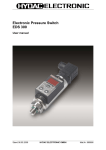
Electronic Pressure Switch
EDS 8000
(Menu navigation according to VDMA)
User Manual
(Translation of original instructions)
Status 09.09.2009
HYDAC ELECTRONIC GMBH
Part No. 669820
User manual EDS 8000 US
Page 2
Table of Contents
1
SAFETY INFORMATION...................................................................3
2
FUNCTIONS OF THE EDS 8000.......................................................3
3
INSTALLATION.................................................................................3
4
CONTROLS OF THE EDS 8000 .......................................................4
5
DIGITAL DISPLAY ............................................................................4
6
OUTPUT FUNCTION.........................................................................7
6.1 Switching Outputs ...........................................................................7
6.1.1 Switch point setting (SP) ....................................................................7
6.1.2 Window function setting (Fno / Fnc)...................................................7
6.2 Setting ranges for the switching outputs ......................................8
7
MENU NAVIGATION .........................................................................9
7.1 Main menu ........................................................................................9
7.2 Extended functions........................................................................10
8
ERROR MESSAGE .........................................................................11
9
PIN ASSIGNMENT ..........................................................................11
10
TECHNICAL SPECIFICATIONS .....................................................12
11
ORDERING DETAILS .....................................................................13
12
ACCESSORIES ...............................................................................14
12.1 For electrical connection...............................................................14
12.2 For mechanical connection...........................................................14
13
Status 09.09.2009
INSTRUMENT DIMENSIONS..........................................................15
HYDAC ELECTRONIC GMBH
Part No. 669820
User manual EDS 8000 US
1
Page 3
Safety Information
Before commissioning,
- check the instrument and any accessories supplied
- read the operating instructions
- ensure that the instrument is suitable for your application.
If the instrument is not handled correctly, or if the operating instructions and specifications
are not adhered to, damage to property or personal injury can result.
2
Functions of the EDS 8000
Depending on which model you have, the instrument offers the following functions:
• Display of the actual pressure in psi, Mpa or bar
• Switching of the switch outputs in accordance with the pressure and the pre-set
switching parameters
• Menu navigation in accordance with the VDMA standard 24574-1
• Coloured LED backlight indicates the switching status
3
Installation
The EDS 8000 can be mounted directly via the pressure connection or indirectly
on a hydraulic block using a hose or a minimess line
(for torque value, see Chapter 9 - Technical specifications).
For optimum alignment, we recommend connecting the EDS 8000 mechanically using a
rotating adapter (for Mechanical Accessories see Chapter 12.2).
The electrical connection must be carried out by a qualified electrician according to the
relevant regulations of the country concerned (VDE 0100 in Germany). The housing of
the pressure switch must be properly earthed. When fitting into a hydraulic block, it is
sufficient if the block is earthed via the hydraulic system. When installing with a minimess
hose, the housing must be earthed separately (e.g. with a screened cable).
CAUTION:
The EDS 8000 must be fitted using a suitable open-end wrench
(across flats 27) on the hexagon nut of the pressure connection.
Do not install the EDS 8000 by gripping the housing, as this would damage the
housing or the entire instrument.
Additional installation suggestions which, from experience, reduce the effect of
electromagnetic interference:
• Make line connections as short as possible
• Use screened cabling (e.g. LIYCY 4 x 0.5 mm²)
• The cable screening must be fitted by qualified personnel subject to the ambient
conditions and with the aim of suppressing interference
• Keep the unit well away from the electrical supply lines of power equipment, as well
as from any electrical or electronic equipment causing interference
Status 09.09.2009
HYDAC ELECTRONIC GMBH
Part No. 669820
User manual EDS 8000 US
4
Page 4
Controls of the EDS 8000
2 keys (↓↑ and E) for adjusting the switch points, switchback points and additional functions
4-digit
digital display
LED backlight
to indicate switch points
(red = active / green = inactive)
E
Use the keys to select the next menu point, or alternatively to adjust the values.
• To scroll through the menu
• To increase the value
E
• To select the menu point
• To confirm value
• Hold the key down to fast-scroll
through the parameter values
5
Digital display
Once the power supply has been switched on, the device briefly flashes "EdS", and then
begins to show the actual pressure.
To check the unit of measurement being used for the pressure indication, press the righthand key. Depending on the setting, bar, psi or MPa will be shown.
The backlight changes colour according to the settings of the switch outputs and their
switch points, i.e. when the switch output is inactive or low-level, the relevant backlight is
"green", when the switch output is active or high-level, the relevant backlight is "red".
Backlight
for switching output 1
Status 09.09.2009
Backlight
for switching output 2
HYDAC ELECTRONIC GMBH
Part No. 669820
User manual EDS 8000 US
Page 5
Reading the digital display
Representation on
7-segment display
Description
Switch point, output 1
Switch-back point, output 1
Switch point, output 2
Switch-back point, output 2
Pressure window upper value, output 1
Pressure window lower value, output 1
Pressure window upper value, output 2
Pressure window lower value, output 2
Extended functions
Reset
Switch delay time, output 1
Switch delay time, output 2
Switch-back delay time, output 1
Switch-back delay time, output 2
Output 1
Output 2
Normally open when hysteresis
function is active
Normally open when window function
is active
Normally closed when hysteresis
function is active
Normally closed when window function
is active
Unit conversion
Units in bar
Units in MPa
Units in psi
Maximum value
Error indication
Delete
Extended functions
Yes
No
Version
Status 09.09.2009
ASCII representation
SP1
sp1
rp1
sp2
rp2
fk1
fl1
fk2
fl2
ef
res
ds1
ds2
dr1
dr2
ov1
ov2
kno
HNO
fno
FNO
knc
HNC
fnc
FNC
uni
bar
mpa
psi
ki
err
--ef
yes
no
Uer
Uni
HYDAC ELECTRONIC GMBH
RP1
SP2
RP2
FH1
FL1
FH2
FL2
EF
RES
dS1
dS2
dR1
dR2
Ou1
Ou2
Bar
MPa
psi
HI
ERR
--EF
Yes
No
Ver
Part No. 669820
User manual EDS 8000 US
Page 6
NOTE:
• If the actual pressure exceeds the instrument's nominal pressure it can no longer
be displayed. The nominal pressure flashes in the display. As a result, when the
menu point Max Value (Hi) is selected, the value of the highest measured
pressure which has been stored flashes until the instrument is reset (rES).
• If the actual pressure is less than 0.6 % of the nominal range, 0 bar is displayed.
Status 09.09.2009
HYDAC ELECTRONIC GMBH
Part No. 669820
User manual EDS 8000 US
6
Page 7
Output function
6.1
Switching Outputs
The EDS 8000 has 2 switching outputs. The following settings can be made under the
basic settings:
6.1.1 Switch point setting (SP)
One switch point and one switch-back point can be set for each switching output. The
particular output will switch when the set switch point is reached and switch back when
the pressure drops below the switch-back point.
Example for switch point 1 (normally closed and normally open function):
On
Normally open function
Off
On
Normally closed function
Off
Abbreviations:
"SP1", "SP2"
"RP1", "RP2"
"HNO",
"HNC"
= switch point 1 / switch point 2
= switch-back point 1 / switch-back point 2
= normally open when hysteresis function is active
= normally closed when hysteresis function is active
NOTE:
• It is only possible to set the switch point (SP) if it is higher than the respective
switch-back point (RP). In the case of low SPs we recommend setting the RP
first.
6.1.2 Window function setting (Fno / Fnc)
The window function allows you to monitor a range. An upper and a lower switch value
can be entered for each switch output. These values determine the range.
The relevant output will then switch when the pressure enters this range.
When the pressure leaves this range, i.e. when the switch-back point has been reached,
the output switches back. The lower switch-back value is just below the lower switch
value. The upper switch-back value is just above the upper switch value. The range
between the switch value and the switch-back value forms a safety margin which
prevents unwanted switching operations from being triggered (such as those triggered by
the pulsations of a pump).
Status 09.09.2009
HYDAC ELECTRONIC GMBH
Part No. 669820
User manual EDS 8000 US
Page 8
Example for switch output 1 (normally closed and normally open function):
P
Off
Aus
FH1 plus 0,4%FS
FH1
FL1
FL1 minus 0,4%FS
Rückschaltwert
Reverse switch point
Schaltwert
Switch point
Sicherheitszone
Safety zone
Ein
On
Ein
On
Aus
Off
t
FNO
Ein
On
Schlie
ßerfunktion
Normally open
function
Schaltwert
Switch point
Rückschaltwert
Reverse switch point
Sicherheitszone
Safety zone
Aus
Off
FNC
Ein
On
Öffnerfunktion
Normally closed
function
Abbreviations:
Aus
Off
"FH1", "FH2"
"FL1", "FL2"
"FNO"
"FNC"
= upper switch value 1 / upper switch value 2
= lower switch value 1 / lower switch value 2
= normally open when window function is active
= normally closed when window function is active
NOTE:
• It is only possible to set the switch point (SP) if it is higher than the respective
switch-back point (RP). In the case of low SPs we recommend setting the RP
first.
• The window function only works properly (switching on and off) if all switch
values (including the safety margin) are above 0 bar and below the nominal
pressure range.
6.2
Setting ranges for the switching outputs
Measuring
range
in psi
0 .. 500
0 ..1000
0 ..3000
0 ..6000
0 ..9000
Lower limit of
RP / FL
in bar
in psi
0.. 25
5
0.. 40
10
0 ..100
30
0 ..250
60
0 ..400
90
0 ..600
in bar
0,25
0,40
1,00
2,50
4,00
6,00
Upper limit of SP Min. difference
/ FH
between
RP and SP or
FL and FH
in psi
in bar
in psi
in bar
500
25
5
0,25
1000
40
10
0,40
3000
100
30
1,00
6000
250
60
2,50
9000
400
90
4,00
600
6,00
Increment
in psi
1
2
5
10
20
in bar
0,05
0,10
0,20
0,50
1,00
1,00
* All ranges given in the table can be adjusted by the increments shown.
Status 09.09.2009
HYDAC ELECTRONIC GMBH
Part No. 669820
User manual EDS 8000 US
7
Page 9
Menu navigation
The EDS 8000 can be adapted to suit the particular application as required by changing
multiple settings. These settings are combined in a single menu.
NOTE:
• If no key is pressed for approx. 60 seconds, the menu closes automatically,
and any changes that may have been made will not be saved.
• If both keys are pressed at the same time, the menu closes automatically
and any changes made are saved.
• When an adjusted parameter is confirmed, the set value is displayed for a
second before returning to the relevant menu point.
7.1
Main menu
Extended
functions
Status 09.09.2009
HYDAC ELECTRONIC GMBH
Part No. 669820
User manual EDS 8000 US
7.2
Page 10
Extended functions
Status 09.09.2009
HYDAC ELECTRONIC GMBH
Part No. 669820
User manual EDS 8000 US
8
Page 11
Error message
If an error is detected, a corresponding error message appears that must be
acknowledged by pressing any key.
Possible error messages:
E.10
A data error was detected in the saved settings. This could be due to strong
electromagnetic interference or a component fault.
Action:
Press E and confirm "RES" by pressing "Yes". The factory settings will be
restored for all adjustable parameters and all minimum and maximum values
will be deleted. Enter the data again from the beginning.
E.12
An error was detected in the saved calibration data. This could be due to
strong electromagnetic interference or a component fault.
Action:
Disconnect then reconnect the supply voltage to the instrument. If the error
persists, the instrument must be returned to the factory for recalibration or
repair.
E.21
A communication error was detected within the instrument. This could be due
to strong electromagnetic interference or a component fault.
Solution:
Press E . If the error persists, disconnect then reconnect the supply voltage
to the instrument. If the error still persists, please contact our service
department.
9
Pin assignment
Version with 2 switch outputs:
Male 4 pole, M12x1
250 mA
EDS 8446-2
84x6-2
EDS
250 mA
Status 09.09.2009
HYDAC ELECTRONIC GMBH
Part No. 669820
User manual EDS 8000 US
Page 12
10 Technical specifications
Input data
Measuring ranges
500; 1000; 3000; 6000; 9000 psi
25; 40; 100; 250; 400; 600 bar
1160; 2900; 7250; 11600; 14500 psi
80; 80; 200; 500; 800; 1000 bar
2900; 7250; 14500; 29000; 29000 psi
200; 200; 500; 1000; 2000; 2000 bar
SAE 6 9/16-18UNF2A; G1/4 A DIN 3852, Form E
15 lb-ft (20 Nm)
Mechanical connection: stainless steel
Sensor cell: stainless steel
Seal: FPM
Overload pressures
Burst pressure
Mechanical connection
Torque value
Parts in contact with fluid:
Output data
Accuracy to DIN 16086,
Max. setting (Display)
Repeatability
Temperature drift
Long-term stability
Switch outputs
Type
Switching current
Switching cycles
Reaction time
Ambient Conditions
Compensated temperature range
Operating temperature range *
Storage temperature range
Fluid temperature range *
Nominal temperature range of display
(read-out)
mark
Vibration resistance to
DIN EN 60068-2-6 at 0 .. 500 Hz
Shock resistance to
DIN EN 60068-2-29 (11 ms)
Protection class to DIN 40050
Other data
Supply voltage
Current consumption
Display:
Life expectancy
Weight:
≤ ± 0.5 % FS typ.
≤ ± 1 % FS max.
≤ ± 0.5 % FS max.
≤ ± 0.017 % FS / °F [0.03 % / °C] max. zero point
≤ ± 0.017 % FS / °F [0.03 % / °C] max. range
≤ ± 0.25 % FS / year max.
2 PNP transistor outputs
max. 250 mA per switching output
> 100 million
< 10 ms
-13 .. +185 °F
-13 .. +212 °F
-40 .. +185 °F
-13 .. +257 °F
+5 .. +185 °F
[-25 .. + 85 °C]
[-25 .. + 100 °C]
[-40 .. + 85 °C]
[-25 .. + 125 °C]
[-15 .. + 70 °C]
EN 61000-6-1 / 2 / 3 / 4
approx. 10 g
approx. 50 g
IP 67 (when an IP 67 connector is used)
9.6 .. 32 V DC
max. 35 mA
(inactive switch output)
4-digit, LED, 7-segment,
Height of digits 4.5 mm
> 10 million cycles (0 .. 100 %)
approx. 70 g
FS (Full Scale) = relative to the complete measuring range
* extended temperature range possible. By separate request.
Status 09.09.2009
HYDAC ELECTRONIC GMBH
Part No. 669820
User manual EDS 8000 US
Page 13
11 Ordering details
EDS 8 4 x 6 - 2 - XXXX - x00
Version (technology)
4
= Thin-film sensor cell
Mechanical connection
4
= G 1/4 A DIN 3852 (male)
(only in combination with bar ranges)
7
= SAE 6 9/16-18UNF2A (male)
(only in combination with psi ranges)
Electrical connection
6
= male M12x1, 4 pole
(connector not supplied)
Output
2
= 2 switching outputs
Pressure range
0500; 1000; 3000; 6000; 9000 psi
(only in combination with mechanical connection “7” -SAE6-)
0025; 0040; 0100; 0250; 0400; 0600 bar
(only in combination with mechanical connection “4” -G 1/4-)
Modification number
400 = Standard in psi
000 = Standard in bar
Status 09.09.2009
HYDAC ELECTRONIC GMBH
Part No. 669820
User manual EDS 8000 US
Page 14
12 Accessories
12.1
For electrical connection
ZBE 06 (4 pole)
Female connector, right-angle
Part No.: 6006788
ZBE 06-02 (4 pole)
Female connector, right-angle with
2m cable,
Part No.: 6006790
ZBE 06-05 (4 pole)
Female connector, right-angle
with 5m cable
Part No.: 6006789
Colour code: Pin 1:
Pin 2:
Pin 3:
Pin 4:
12.2
brown
white
blue
black
For mechanical connection
ZBM 14
Adapter female thread G1/4 - male
thread G1/4 (rotating)
Part No.: 907818
Status 09.09.2009
HYDAC ELECTRONIC GMBH
Part No. 669820
User manual EDS 8000 US
Page 15
13 Instrument dimensions
snubber
Status 09.09.2009
HYDAC ELECTRONIC GMBH
Part No. 669820
User manual EDS 8000 US
Page 16
HYDAC ELECTRONIC GMBH
Hauptstr.27
D-66128 Saarbrücken
Germany
Web: www.hydac.com
E-Mail: [email protected]
Tel.: +49 (0)6897 509-01
Fax.: +49 (0)6897 509-1726
HYDAC Service
For enquiries about repairs or alterations, please contact HYDAC Service.
HYDAC SERVICE GMBH
Hauptstr.27
D-66128 Saarbrücken
Germany
Tel.:
Fax.:
+49 (0)6897 509-1936
+49 (0)6897 509-1933
Note
The information in this manual relates to the operating conditions and applications described. For
applications and operating conditions not described, please contact the relevant technical
department.
If you have any questions, suggestions, or encounter any problems of a technical nature, please
contact your Hydac representative.
Subject to technical modifications.
Status 09.09.2009
HYDAC ELECTRONIC GMBH
Part No. 669820