1
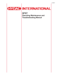
L-4138
MAFH-E
Operating Maintenance and
Troubleshooting Manual
*US Patent Pending
L-4138 | Created 9.2012
User Manual
MAFH
L-4138
- TABLE OF CONTENTS1. Introduction ………………………………………………………………………………………………………………………...4
2. Warnings, Cautions and Notes …………………………………………………………………………………………………5
3. Commissioning …………………………………………………………………………………………………………………...6
3.1 Transport and Packing ..........................……………………………………………………………………………………..6
3.2 Set-up .....................................………………………………………………………………………………………………..6
4. Connection ..………………………………………………………………………………………………………………………..7
4.1 Suction port connection ........................……………………………………………………………………………………..7
4.2 Pressure port connection ........………………………………………………………………………………………………..7
4.3 Electrical connection …………………………………………………………………………………………………………..7
5. Specifications ..............…………………………………………………………………………………………………………...7
6. Components .....................………………………………………………………………………………………………………..8
7. Operating Instructions .....………………………………………………………………………………………………………..10
7.1 Operator interface controls …………………………………………………………………………………………………...11
7.1.1 Main Screen ........………………………………………………………………………………………………………..11
7.1.2 Operation Mode ……....…………………………………………………………………………………………………11
7.1.3 Automatic Mode ...……………………………………………………………………………………………………….12
7.1.4 Setting the Fluid Temperature ..………………………………………………………………………………………..13
7.1.5 Recorded Time Screen …………………………………………………………………………………………………13
7.1.6 Percent Water Saturation History Screen ...………………………………………………………………………….13
7.1.7 Automatic Mode System Status ........…..……………………………………………………………………………..14
7.1.8 Fluid Oscillation in Automatic Mode ………………...…………………………………………………………………14
7.1.9 Spray Loop Drive Settings ...……………………..…………………………………………………………………….15
7.1.10 Drain Cycle Time Screen ........………………………………………………………………………………………..15
7.1.11 Manual Mode ..……....…………………………………………………………………………………………………16
7.1.12 System Faults ...…….………………………………………………………………………………………………….16
7.1.13 Maintenance Functions/Guides ...…….……..……………………………………………………………………….17
8. Maintenance Instructions …………….………………………………………………………………………………………….18
8.1 Servicing Filter Elements ......................……………………………………………………………………………………..18
8.2 Servicing the Air Breathers ........……………………………………………………………………………………………..18
8.3 AC Motors ................…………………………………………………………………………………………………………..18
8.4 Replacement Parts .....................……………………………………………………………………………………………..18
8.5 Inspection and Maintenance Schedule ........………………………………………………………………………………..19
9. Warranty ............................…………….………………………………………………………………………………………….20
Appendix 1A - Hydraulic Schematic …………………………………………………………………………………………..21
Appendix 2A - Electrical Schematic …………………………………………………………………………………………...22
Appendix 3A - Floor Mounting Holes ………………………..………………………………………………………………..26
Appendix 4A - Troubleshooting ....................…………………………………………………………………………………27
HYDAC
En
TOC
L-4138MAFH User Manual
1. INTRODUCTION
HYDAC International’s patent pending Dehydration Station (MAFH) is the first of its kind on the market. The MAFH offers fully automated dewatering of hydraulic fluids and a variety of other petroleum based fluids.
The operating principle of the MAFH differs from existing dewatering methods. The MAFH is a positive pressure system that uses 100% mass transfer to remove water from the operating fluid. Room air is heated using a proprietary method to improve the ability of the air to absorb water vapor. This heated air is then distributed upwards in the reaction chamber through cascading droplets of operating fluid. The heated air stream removes free, emulsified, & dissolved water and some dissolved gases.
In most traditional industrial vacuum dehydrators, mass transfer is also the means to dewater. A mild/medium vacuum
expands the room air and proportionately reduces the relative humidity of the air. The air flow is limited to the
displacement of the vacuum pump. Higher efficiency vacuum units use a closed cycle to seal operating fluid with high
heat and high vacuum to boil off water. These units have high efficiency but have low flow rates and can potentially
damage the operating fluid over time.
Since the air flow rate of the HYDAC MAFH is not limited by vacuum pump displacement, it is more effective in dewatering operating fluids under similar conditions and flow rates than the above technologies. In addition, the MAFH does not have the initial and maintenance economic disadvantages of a vacuum pump based system.
The MAFH uses a regenerative air injection system to heat and distribute room air into the reaction chamber. Any residual fluid mist is mechanically separated from the moist air stream before it is vented from the chamber. The system fluid is cycled through the reaction chamber via a system of two gear pumps, one speed regulated, one fixed speed then filtered. During a cycle, fluid is pumped from a customer reservoir, through an inlet strainer, with the speed regulated pump and gently sprayed on top of the loose, reticulated media. The fluid is pumped (fixed speed pump) from the sump through a 3-micron filter and returned to the customer reservoir. The VFD constantly regulates the motor speed to provide a constant flow of oil to the reaction chamber thereby affording a continuous water removal process.
The MAFH control system monitors system functions and manages the cycle operation. An on-board water sensor (AS1000) senses the relative humidity of the operating fluid and displays the actual humidity value at the control panel.
4En
HYDAC
User Manual
MAFH
L-4138
2. WARNINGS, CAUTIONS AND NOTES
Recognize Safety Information
This is the safety alert symbol. When you see this symbol on your machine or in this manual, be alert
for the potential of personal injury. Follow the precautions and safe operating practices highlighted by this symbol.
A signal word — DANGER, WARNING, or CAUTION — used with the safety alert symbol. DANGER identifies the most serious hazards. General precautions are on CAUTION labels.
Follow Safety Instructions
Read the safety messages in this manual and on the machine. Follow these warnings and instructions carefully. Review them frequently. Be sure all operators of this machine understand every safety message. Replace safety labels immediately if missing or damaged.
Operate Only If Qualified
Do not operate this machine unless you have read the operator’s manual carefully and you have been qualified by supervised training and instruction. Familiarize yourself with the job site and your surroundings before operating.
Inspect Machine
Inspect the equipment carefully before each use. Keep all parts in good condition and properly installed. Fix damage and replace worn or broken parts immediately. Pay special attention to hydraulic hoses and electrical power cord.
Handle Fluids Safely—Avoid Fires
Filtering of fuel or other flammable liquids is not recommended. Store flammable fluids away from fire hazards. Do not incinerate or puncture pressurized containers. Make sure machine is clean of trash, grease, and debris. Do not store oily rags; they can ignite and burn spontaneously.
Prepare for Emergencies
Be prepared if a fire starts. Keep a first aid kit and fire extinguisher handy. Keep emergency numbers for doctors, ambulance service, hospital, and fire department near your telephone.
Practice Safe Maintenance
Understand service procedure before doing work. Work area should level, clean, and dry. Before servicing machine:
- Position machine on a level surface
- Allow to cool if hot
Keep all parts in good condition and properly installed. Fix damage immediately. Replace worn or broken parts. Remove any buildup of grease, oil, or debris.
Handle Chemical Products Safely
Direct exposure to hazardous chemicals can cause serious injury. Potentially hazardous chemicals used with equipment include such items as lubricants, coolants, paints, and adhesives. A Material Safety Data Sheet (MSDS) provides specific details on chemical products: physical and health hazards, safety procedures, and \
emergency response techniques. Check the MSDS before you start any job using a hazardous chemical. That way you will know exactly what the risks are and how to do the job safely. Then follow procedures and recommended equipment. (Contact Schroeder Industries prior to using with fluids other than hydraulic fluids).
Wear Protective Clothing
Wear close fitting clothing and safety equipment appropriate to the job. Operating equipment safety requires the full attention of the operator. Do not wear radio or music headphones while operating the machine.
Service Machines Safely
Tie long hair behind your head. Do not wear a necktie, scarf, loose clothing, or necklace when you work near machine tools or moving parts. If these items were to get caught, severe injury could result. Remove rings and other jewelry to prevent electrical shorts and entanglement in moving parts.
HYDACEn
5
L-4138MAFH User Manual
Illuminate Work Area Safely
Illuminate your work area adequately but safely. Use a portable safety light for working inside or under the machine. Make sure the bulb is enclosed by a wire cage. The hot filament of an accidentally broken bulb can ignite spilled fuel or oil.
Work In Clean Area
Before starting a job:
- Clean work area and machine
- Make sure you have all necessary tools to do your job.
- Have the right parts on hand.
- Read all instructions thoroughly; do not attempt shortcuts.
Use Proper Tools
Use tools appropriate to the work. Makeshift tools and procedures can create safety hazards. For loosening and tightening hardware, use the correct size tools. DO NOT use U.S. measurement tools on metric fasteners. Avoid bodily injury caused by slipping wrenches.
Dispose of Waste Properly
Improperly disposing of waste can threaten the environment and ecology. Use leak-proof containers when draining fluids. Do not use food or beverage containers that may mislead someone into drinking from them. Do not pour waste onto the ground, down a drain, or into any water source.
3. Commissioning
3.1 Transport and packing
■ All MAFH units are tested at the factory for leaks and function. They are then carefully packaged for shipment.
■ The fluid connections are all sealed with plugs to prevent the intrusion of contaminants during transport. ■ Upon receipt of the unit, check for any damage from transportation.
■ The packaging material should be re-used/re-cycled as appropriate for your area.
■ These Operating and Maintenance Instructions are a component part of the MAFH.
■ To lift the MAFH please use the ring bolts.
■ If it is not necessary to lift the MAFH, its wheels may be sufficient to push it to its new emplacement.
■ Take care to evacuate the reactor and the fluid filter and to close the drain valve before transport.
As the MAFH weighs more than 1000 lbs we recommend transporting with two people
3.2 Set-up
■ The unit must be mounted level and on flat surface, Do not tilt beyond 15 degrees. No special mounting is required (the brakes at the wheels must be blocked!)
■ The MAFH should be located near the tank (length of the hoses 15ft. max.), difference in height between the tank and the MAFH is 7 feet maximum.
■ Sufficient room to operate and maintain the unit must be left around the MAFH.
■ No positive or back pressure.
6En
HYDAC
User Manual
MAFH
L-4138
4. Connection
4.1 Suction port connection
■ The suction port may be connected to a flexible hi-collapse hose, or to hard piping. The nominal size of the connected hoses/piping, must be at least as large as the inlet/outlet port sizes of the MAFH in order to prevent an excessively high negative suction pressure.
■ Make sure that the tank connection is always below the fluid level.
■ Do not prime the fluid from the sump of the tank where high contamination may affect the operation
of the unit
4.2 Pressure port connection
■ The return line must also be installed below the fluid level in order to prevent air being introduced into the system again.
4.3 Electrical connection
■ The voltage and frequency given on the type plate, must agree with that of the power supply.
■ Connection: 3 x L+ PE. Conductor is not necessary.
The electrical connection must be carried out by a qualified electrician. All local and national electrical regulations and codes must be adhered to.
5. Specifications
Dimensions: 32ʺ W x 59ʺ L x 70.25ʺ H
Dry Mass: 1000 lbs (453 kg)
Inlet Connections: 1-1/2ʺ MJIC
Outlet Connections: 1-1/4ʺ MJIC
Flow Rate: 900 gallons/hour
Inlet Pressure: Atmospheric
Outlet Pressure: to 125 psi (8.62 Bar)
Fluid Service Temperature 50° F to 175° F
(10° C to 79° C)
Fluid Viscosity: 70 - 2000 SUS
Power Supply: 460V/3/60Hz, 7Amps
460V/3/60Hz, 22.5 Amps w/ heater
575V/3/60Hz, 5.5 Amps
575V/3/60Hz, 18 Amps w/ heater
Relative Humidity Display: Standard, 0-99% Range
Attainable Water Content: <50 PPM
Construction: Base Frame: Carbon Steel
Vessel: Stainless Steel
Seals: Viton
HYDACEn
7
L-4138MAFH User Manual
6. Components
Number Description
Number Description
1
HOUSING
14
COUPLING HALF, MOTOR
2
BREATHER
15
COUPLING HALF, PUMP
3
LEVEL SWITCH
16
COUPLING , INSERT
4
BLOWER
17
ELECTRIC MOTOR, SPRAY
5
HEATER, IF REQUIRED
18
ELECTRIC MOTOR, DRAIN
6
CONRTOL PANEL
19
CASTER, SWIVEL
7
TEST, CONNECTOR
20
LEVEL SWITCH, FLOAT
8
VACUUM GUAGE
21
STRAINER, Y
9
FRAME
22
VALVE SAMPLE & HOSE
10
CASTER, FIXED
23
FILTER
11
PUMP, GEAR
24
DIRT ALARM, ELECTRIC
12
SENSOR, WATER
25
VALVE, CHECK, INLINE
13
ADAPTER, PUMP
8En
HYDAC
User Manual
MAFH
L-4138
6. Components - Component reference view
6. Components - Filter Element/Indicator reference
Number Description
1
Filter Support
2
Dirt Alarm, Electric
3
Filter Cap
4
Valve, Sample
5
Hose
HYDACEn
9
L-4138MAFH User Manual
7. Operating Instructions
2
1
3
6
4
5
External Panel Components
1. Main Disconnect
Move the main switch to the “ON” position and wait until the
touch panel displays the main screen.
2. Operator Interface
Touch panel and six hard-keys “F1 thru F6”, described in
section 6.2
3. Fault light
All System Faults will cause the Red Light to Flash
4. Status light
CYCLE COMPLETE = Solid Amber Light
HEATER ACTIVE = Flashing Amber Light
5. Emergency stop
Push to employ the hard-stop
Pull to release the E-stop and press hard-key “F3” to reset
the fault.
6. Grace port
(right side access door)
120VAC @ 3Amps Laptop Receptacle
Ethernet Communications Port; connected to PLC Network
10En
HYDAC
User Manual
MAFH
L-4138
7.1 Operator Interface Controls
7.1.1 MAIN SCREEN
From the “MAIN SCREEN”, the user has the option of entering Operation Functions, Maintenance Functions or System Information screens.
SYSTEM INFORMATION – includes touch screen calibrations, program transfers, touch screen user administration and the touch screen’s model information.
7.1.2 Operation Mode
The “OPERATION MODE” screen gives the user the choice between automatic and manual operation. Back will take the user to the Main Screen.
WARNING! During initial start-up of the MAFH unit, the suction line should be flooded with fluid to prime the MAFH pump. Do not run the pump without fluid in the suction line or pump damage will occur!
HYDACEn
11
L-4138MAFH User Manual
7.1.3 Automatic Mode
NOTE: Once started the MAFH will continue to run in Auto Mode, unless the user enters the “MANUAL MODE”
Screen 7.1.11. The hard-keys “F1” – “F3” at the bottom of the screen allow the user to control the unit and explore the
Maintenance Functions and Guides 7.1.13.
■ Default temperature and saturation set points
need to be entered to run in automatic mode.
Select “Set Point” under Saturation and enter your
value. Select “Set Point” under Temperature to
enter the desired default temperature value. The
temperature set point is only available on units
equipped with a heater.
■ The MAFH will operate without any user
intervention until the fluid saturation is below the
set point for longer than two minutes.
■ The current % saturation can then be observed
on the scale. All values during testing can be reset
by selecting the appropriate “Set Point” again. A
15 minute trend history can be view by clicking the
scale.
■ The “%SAT TREND” button will display detailed
history of the current cycle’s saturation levels, refer
to section 7.1.6 for more details.
■ If the fault light turns on during automatic mode,
you will be directed to the corresponding “SYSTEM
FAULTS” screens 7.1.6 to observe and reset the
cause of the alarm.
The “F1” button is the stop button
available on every screen. It will stop
the spray pump immediately, but the
drain pump will continue for a short
amount of time to try to empty the
reactor.
The “F2” button is the start command
for Auto Mode and is only available on
select screens.
The “F3” push button is used to reset
any System Faults. A cause for
the shut down will be listed on the
“SYSTEM FAULTS” 7.1.12
The MAFH unit is equipped with a Remote Start Option, to start “Auto Mode” remotely connect a 120VAC maintained signal to terminals 470A1 and A70A2, refer to APPENDIX 2A – ELECTRICAL SCHEMATIC.
The unit will only stop remotely if there is a remote start signal is present, and then it is removed. All local controls can override the remote start signal. Entering the Manual Mode Screen 7.1.11 will exit “Auto Mode” and shutdown the motors.
12En
HYDAC
User Manual
MAFH
L-4138
7.1.4 Setting the Fluid Temperature
Set the fluid temperature by following these steps through
the touch panel.
■ Click on “OPERATION” on the main screen, shown in
section 7.1.2
■ Click on “AUTO MODE” on the operation functions screen,
shown in section 7.1.3
■ Click on the I/O field shown as “+0” below “Set Point”
in the Temperature section on the MAFH automatic mode
screen. The following keypad will display.
■ Type the desired temperature followed by enter.
Note: The maximum allowed temperature is 135°F.
7.1.5 Recorded Time Screen
This screen can be accessed by pressing below “ELAPSED
TIME” on the “AUTO MODE” screen 7.1.3.
■ “HOUR METER” – Records the total operation time of the
MAFH.
■ “TRIP METER” – A reset able operation timer. Useful for
Preventative Maintenance schedules.
■ “CYCLE COMPLETE” – Records the time the MAFH has
remained inoperative due to the fluid’s Saturation being
below the user’s set point.
■ “FAULT TIME” - Records the time the MAFH has remained
inoperative due a system fault.
■ “AUTO MODE TIME” - Records the time the MAFH
has operated continuously in Auto Mode. The timer
automatically resets each time a new cycle is started.
7.1.6 Percent Water Saturation History Screen
This screen can be accessed by pressing the “%SAT
TREND” button in the “AUTO MODE” screen 7.1.3 or “%”
button in the “SYSTEM STATUS” screen 7.1.7.
■ This read-only screen will record the elapsed time of the
current cycle it took the percent water saturation to reach
ten benchmarks (10% - 100%, in 10% increments).
■ The running time stamps are retained until a new Auto
Mode cycle is started, by pressing the hard-key “F2”, even if
the power is lost.
■ The system will not record values during a short interval
at start-up to allow the system to complete flush, therefore
preventing false readings.
HYDACEn
13
L-4138MAFH User Manual
7.1.7 Automatic Mode System Status
This screen can be accessed by pressing the “SYSTEM
STATUS” button in the “AUTO MODE” screen 7.1.3.
■ This screen provides a summary of the inputs’ and
outputs’ current status.
■ Active outputs are highlighted by
checkmarks.
The “F1” button is the stop button available on every screen. It will stop the spray pump immediately, but the drain pump will continue for a short amount of time to try to empty the reactor. Use the E-Stop to shutdown all pumps instantly.
7.1.8 Fluid Oscillation in Automatic Mode
The system fluid is cycled through the reaction chamber in-between two level switches. During the first cycle, fluid is pumped and gently sprayed on top of the loose, reticulated media until the fluid level in the sump triggers the high float switch. The fluid is then pumped from the sump and returned to the customer’s reservoir. After the initial cycle the spray and drain pumps are synchronized to continuously pump fluid in both directions.
The MAFH-E controls are designed with a staged start-up sequence in Auto Mode to help reduce the current spikes
associated with motors’ start-up. When the reaction chamber is empty the normal sequence is the spray pump will ramp-
up to speed slowly, followed by the blower motor, and then the optional heater, if necessary, will engage. If the cycle was stopped with the fluid above the top float switch, at the next start-up the Drain pump will operate independently until the fluid is within the normal levels.
14En
HYDAC
User Manual
MAFH
L-4138
7.1.9 Spray Loop Drive Settings
This screen can be accessed by pressing “GPM” in the
“AUTO MODE” screen 7.1.3, the “STATUS” screen 7.1.7, or
“MANUAL MODE” screen 7.1.11.
■ Cycle Time History can be viewed by pressing one of
buttons on the bottom left half of the screen.
■ Each time the power is cycled the default “Auto-Tuning”
Function will be enabled. This function uses the Cycle Time
History data to synchronize the pump speeds.
■ Users can disable the “Auto-Tuning” Function by pressing
the button on the bottom right half of the screen.
■ With a Users’ password the flow rates can be adjusted in
the following ranges:
“Fill Speed Flow Rate” = 15.5 – 16.5GPM
“Flow Rate Offset” = 2 – 5GPM
■ Authorized users can modify these settings for Diagnostic
purposes outside this range. These valves will return to
their default valves after the power is cycled and if the
“Auto-Tuning” Function is disabled.
The flow rates should only be adjusted if repetitive faults are
present. Contact the factory for the correct password.
7.1.10 Drain Cycle Time Screen
This read-only screen displays the “Drain Cycle” time
information in minutes.
■ Similar to “Saturation History” Screen 7.1.6 the longest
cycle time is marked by a running time stamp (elapsed time
of the current cycle).
■ In addition, the time during the “Drain Cycle” when the
high float switch is energized is recorded.
■ All information is retained until a new Auto Mode cycle is
started, by pressing the hard-key “F2”, but if the power is
lost the data is reset.
Note: Identical information is stored for the “Fill Cycle” on a
separate screen.
HYDACEn
15
L-4138MAFH User Manual
7.1.11 Manual Mode
Manual mode is intended as a diagnostic tool only. The system can be damaged by improper use or left unsupervised. The processor will shut down the system after 15 minutes.
The three motors can be controlled individually to cycle fluid in and out of the reactor, by pressing the icon. MAFH units equipped with a heater can manually heat the fluid if the Spray Pump is running and the temperature is below 135°F. Similar to the “SYSTEM STATUS” screen 7.1.7, this screen also displays the status of the float switches. The user can toggle between the “Fill Speed” and “Drain Speed” flow rates.
7.1.12 System Faults
This screen can only be accessed when a fault is present. A
“Fault Present” button will appear in the bottom right corner
of the majority of the screens described here.
■ Press hard-key “F3” to reset all faults at one time. If
the fault condition was not corrected the description will
reappear.
■ By pressing the faults’ description the user will be taken to
the Troubleshooting section of the touch screen. This page
will provide instructions to clear known fault conditions.
■ For a complete description of all the faults refer to
APPENDIX 3A – TROUBLESHOOTING.
16En
HYDAC
User Manual
MAFH
L-4138
7.1.13 MAINTENANCE FUNCTIONS / GUIDES
The MAFH Maintenance screen allows the user to review
select sections of the user’s manual on the touch panel.
■ Safety Information: Provides basic safety information
and instructions the user must follow while operating the
MAFH.
■ Maintenance Schedule: This section provides the user
the schedule that needs to be followed to ensure correct
maintenance. There are inspection and maintenance
schedules in the following categories: General, Fluid Filter,
Electrical, Functional Test, and Drain / Spray Pumps.
■ Maintenance Procedures: This section provides the
user with step-by-step maintenance procedures to follow to
ensure correct maintenance.
■ Troubleshooting: This section of the manual provides
information regarding basic problems encountered while
operating the MAFH. On these screens, the user can find
the cause and remedy of the problem by locating the error
message.
■ Commissioning: This section of the manual provides
information regarding transport and packing, set-up,
connection, start up, and storage.
■ Spare Parts: This section of the manual provides
information regarding spare parts. It contains a list of basic
components of the MAFH with their HYDAC part number.
Contact HYDAC with any part not listed or with a “per
inquiry” part number.
■ Screen Maintenance: To update screen software, adjust
contrast, and calibrate the screen.
■ Technical Data: This section of the manual provides
information regarding basic technical data of the spray
pump, drain pump, heater, and the MAFH unit.
■ Contact HYDAC International: This screen provides
all information needed to contact HYDAC for product
information, technical support, or for any suggestions for
improvement related to the maintenance instructions.
HYDACEn
17
L-4138MAFH User Manual
8. Maintenance Instructions
No maintenance operations should be carried out while the unit is running. Before starting any other maintenance operations, ensure that the system is shut down and electrically isolated.
8.1 Servicing Filter Elements
Do not run the system without a filter element installed. Use only specified replacement filter elements. Access to the fluid filter element is from the side of the unit. See section 4 for location.
8.2 Servicing the Air Breathers
The air breathers are simply hand tightened. Used breathers may require a wrench to remove. The (2) air breathers used are identical. Breather element or entire unit may be replaced.
8.3 AC Motors
The motor should be inspected at regular intervals (every 500 hours of operation or every 3 months, whichever occurs first). Keep the motor clean and the ventilation openings clear.
During operation, listen for unusual noises, especially in the areas around the bearings. Rumbling or rubbing noises could be signs of internal damage.
8.4 Replacement Parts
Since minimum repair service is generally required on these units, it is recommended that any failed parts be replaced with new parts. See the following parts list:
Component
Part Number
Filter Element
02094523
Indicator
02094524
Air Breather
02062754 (2) REQ‘D
Please refer to component list drawings in section 6 for locations of replacement parts.
WARNING! Performance of the MAFH-E is based upon the use of HYDAC filter elements. The MAFH-E is designed around the pressure drops and specifications of the specified HYDAC elements.
18En
HYDAC
User Manual
MAFH
L-4138
8.5 Inspection and Maintenance Schedule
The schedule listed below is intended to be an indication of the inspections and maintenance work to ensure a long lifetime and faultless operation.
TASK
CHECK FOR LEAKAGE
DAILY 24 HRS
MONTHLY 500 HRS
1/2 YR 3000 HRS
YEARLY 6000 HRS
X
HOSE & PIPES FOR WEAR
X
INDICATION LAMPS
X
REPLACE AIR BREATHERS
X
REPLACE / CLEAN SUCTION
STRAINER
X
INSPECT & CLEAN FAN
X
CHANGE FILTER ELEMENT
X
DRAIN FILTER HOUSING
X
CHECK CABLE GROMMETS
X
CHECK & COMPARE MOTOR
CURRENT CONSUMPTION
X
ELECTRICAL SAFETY TEST
PER DIN VDE O702 OR
EQUAL REGULATION
CHECK & COMPARE HEATER
CURRENT CONSUMPTION
X
X
CHECK REACTOR LEVEL
SWITCH
CHECK FLOAT SWITCH IN
PAN
X
X
TEST ALL COMPONENTS IN
MANUAL OPERATION
HYDACEn
X
19
L-4138MAFH User Manual
9. Warranty
Warranty, Limitation of Liability and Remedies:
THERE IS NO WARRANTY OF MERCHANTABILITY OR FITNESS FOR ANY PARTICULAR PURPOSE WITH RESPECT TO ANY OF THE PRODUCTS, NOR IS THERE ANY OTHER WARRANTY EXPRESS OR IMPLIED, EXCEPT AS PROVIDED FOR HEREIN.
For a period of twelve months from the date of delivery from Seller or three thousand hours of use, whichever occurs first (the “Warranty Period”, Seller warrants that products manufactured by Seller when properly installed and maintained, and operated at ratings, specifications and design conditions, will be free from defects in material and workmanship. By way of explanation and not limitation, the Seller does not warrant the service life of the filter elements as this is beyond the Seller’s control and depends upon the condition of the system into which the filter is installed.
Seller’s liability under any warranty is limited solely (in Seller’s discretion) to replacing (FOB original ship point), repairing or issuing credit for products that become defective during the Warranty Period. Purchaser shall notify Seller promptly in writing of any claims and provide Seller with an opportunity to inspect and test the product claimed to be defective. Buyer shall provide Seller with a copy of the original invoice for the product, and prepay all freight charges to return any products to Seller’s factory, or other facility designated by Seller. All claims must be accompanied by full particulars, including system operating conditions, if applicable.
Seller shall not be liable for any product altered outside of the Seller’s factory except by Seller or Seller’s authorized distributor, and then, as to the latter, only for products which have been assembled by the distributor in accordance with Seller’s written instructions. Nor shall Seller be liable for a product subjected to misuse, abuse, improper installation, application, operation, maintenance or repair, alteration, accident or negligence in use, storage transportation or handling.
In no event will Seller be liable for any damages, incidental, consequential or otherwise, whether arising out of or in connection with the manufacture, packaging, delivery, storage, use, misuse, or non use of any of its products or any other cause whatsoever.
SERVICE
Shipping Address for Recalibrating and Repair Work
HYDAC International
2260 City Line Rd
Bethlehem, PA 18017
20En
HYDAC
User Manual
MAFH
L-4138
HYDACEn
21
APPENDIX 1A - HYDRAULIC SCHEMATIC
L-4138MAFH User Manual
APPENDIX 2A – ELECTRICAL SCHEMATIC 460VAC Unit Only
22En
HYDAC
User Manual
MAFH
L-4138
APPENDIX 2A – ELECTRICAL SCHEMATIC (SHEET 1 OF 3) - 575VAC Units Only
HYDACEn
23
L-4138MAFH User Manual
APPENDIX 2A – ELECTRICAL SCHEMATIC (SHEET 2 OF 3)
24En
HYDAC
User Manual
MAFH
L-4138
HYDACEn
25
APPENDIX 2A - ELECTICAL SCHEMATIC (SHEET 3 OF 3)
L-4138MAFH User Manual
APPENDIX 3A – FLOOR MOUNTING HOLES (OPTIONAL)
30.00
55.75
26En
HYDAC
User Manual
MAFH
L-4138
APPENDIX 4A - Troubleshooting
Problem
Unit is connected to power source but
motors will not start.
Cause
Solution
Blown Fuses.
Verify which fuse is blown and replace
with the recommended size.
The pumps’ overload has tripped.
Verify wiring, checking for short
circuits or damaged wires.
Reset overload.
Spray Pump Drove Failure
The spray motor’s drive has a fault
Drain Pump Motor Overload
The drain motor overload has tripped.
Verify wiring, checking for short
circuits or damaged cables.
If issue reoccurs contact factory to
view Fault History Parameters.
Verify wiring, checking for short
circuits or damaged cables.
Verify overload setting and reset.
Blower Overload
The blower’s overload has tripped
Verify wiring, checking for short
circuits or damaged cables
Verify overload setting and reset,
Verify that the inlet to the system is not
The system is running but there is little blocked.
or no flow into the reactor chamber.
Verify that the oil being dehydrated is
within the acceptable viscosity range.
Air Leak in suction hose
No Inlet Flow
Inspect hose for cracks or cuts.
Check for loose inlet fittings. Repair or
replace as needed.
Eliminate restriction or add some fluid
to inlet hose and elevate to prime dry
pump.
Pump not priming
Eliminate excess fittings, valved
couplings, or any other source of high
differential pressure.
Heat fluid until maximum rated fluid
viscosity of unit is reached.
No Discharge Flow
Fluid Overflow
Drip Pan Full
The system is running but there is little Verify that the system discharge is not
or no flow out of the vacuum chamber. blocked.
The reactor’s fluid level is higher than
normal operation.
There is oil in the drip pan.
Wrong Phase Sequence.
PMR Red LED is Flashing.
Phase, Check Wiring
Extreme Fluid Temperature
Verify proper operation of the
discharge pump.
Verify proper operation of the
chamber float switch.
Check for leaks, tighten any fittings
that are loose.
If there is no oil in the pan; check
wiring or replace the float switch.
Switch any two legs of the main three
phase power to reverse the phase.
Check wiring at source connection for
Phase Failure or Under Voltage. PMR
faulty wiring or validate wiring is rated
Red LED is Solid.
for correct ampere load.
Fluid temperature is above the
operating range.
Confirm heater is operating correctly.
Confirm temperature sensor is correct.
HYDACEn
27
L-4138MAFH User Manual
Problem
Cause
Solution
Replace Element Message
Element has reached a bypass or
clogged condition.
Replace Filter Element. If fault continues confirm the cable is connected
and not damaged.
E-Stop Activated
The emergency stop button has been
activated.
Deactivate the switch. If switch is
not activated, verify wiring or replace
switch.
Manual Mode Timer Expired
The system has been in manual mode
for longer than 15 minutes.
Diagnostic mode is for troubleshooting, please refrain from using the
system in manual mode for extended
periods of time. Clear faults to reset
the timer.
Check Sensor Cable
The PLC is no longer receiving a valid
signal from the water / temperature
sensor.
Verify the cable is connected and not
damaged.
Replace Cable.
Replace Water / Temperature Sensor.
Excessive discharge fluid pressure
Excessive pump noise or decreased
system flow
Fluid viscosity high
Heat fluid until maximum rated fluid
viscosity of unit is reached.
Discharge line restriction
Eliminate excess fittings, valved
couplings, or any other source of high
differential pressure.
Pump is worn
Replace Pump
Obstruction in the suction line
Check the suction line fittings and
eliminate restrictions
Open external suction shutoff valve if
installed
Excessive suction fluid pressure
Fluid viscosity high
Heat fluid until maximum rated fluid
viscosity of unit is reached.
Suction line restriction
Eliminate excess fittings, valved
couplings, or any other source of high
differential pressure.
Blocked suction element
Remove and clean suction elements
28En
HYDAC
Internet: www.hydac.com
E-Mail: [email protected]