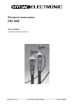
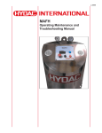
1
L-4219
OFX7
Operating Maintenance and
Troubleshooting Manual
L-2999 | Created 9.2012
User Manual
OFX7
L-4219
- Table of Contents Preface……………………………………………………………………………………………………………………………….4
Customer Service…………………………………………………………………………………………………………….…4
Modifications to the Product……………………………………………………………………………………………………4
Warranty……………………………………………………………………………………………………………………….…4
Introduction…………………………………………………………………………………………………………………………5
Safety Instructions………………………………………………………………………………………………………………...6
Operating Instructions………………………………………………………………………………………………………..…..8
Connect/Disconnect Procedures……………………………………………………………………………………………...8
Routine Cleaning……………………………………………………………………………………………………………......8
Changing elements…………………………………………………………………………………………………………..……9
Removing/Installing Elements………………………………………………………………………………………………....9
Switching Fluids………………………………………………………………………………………………………………..….10
Taking Fluid Samples…………………………………………………………………………………………………………..…11
Product Photo………………………………………………………………………………………………………………….…..12
Appendices………………………………………………………………………………………………………………………….13
Appendix A: Electrical Schematic ……………………………………………………………………………………………14
Notes…...…………………………………………………………………………………………………………………………….16
HYDAC
En
TOC
L-4219OFX7 User Manual
Preface
For you, as the owner of a product manufactured by us, we have produced this manual, comprising the
most important instructions for its operation and maintenance.
It is intended to help you become acquainted with the ins and outs of the product and use it properly.
You should keep it in the vicinity of the product so it is always at your fingertips.
Sometimes the information contained in the documentation cannot always keep up with changes made to
the product as we attach considerable importance to keeping our products cutting-edge. Consequently,
there might be deviations in technical details, illustrations and dimensions.
If you discover errors while reading the documentation or have suggestions or other useful information,
please don’t hesitate to contact us:
HYDAC
2260 City Line Road
Bethlehem, PA 18017
Fax: 610.266.0100
www.hydacusa.com
We look forward to receiving your input.
Our motto: “Putting experience into practice”
Customer Service
If you have any questions, suggestions, or encounter any problems of a technical nature, please don’t
hesitate to contact us. When contacting us, please always include the model/type designation and article
no. of the product:
Fax: 610.266.0100
www.hydacusa.com
Modifications to the Product
We would like to point out that changes to the product (e.g. purchasing options, etc.) may result in the
information in the operating instructions no longer being completely accurate or sufficient.
When making modifications or performing repair work to components affecting the safety of the product,
the product may not be put back into operation until it has been examined and released by a HYDAC representative.
Please notify us immediately of any modifications made to the product whether by you or a third party.
Warranty
For the warranty provided by us, please refer to the General Terms of Sale and Delivery of HYDAC.
They are available at: www.hydacusa.com
4
En
HYDAC
User Manual
OFX7
L-4219
Introduction
HYDAC filtration skids are compact, self contained filtration systems equipped with high efficiency, high
capacity elements capable of removing particulate contamination and/or water quickly, conveniently, and
economically. Over 90% of all hydraulic failures are caused by contaminants in the fluid; proper filtration is essential
in achieving long component life and efficient system operation. HYDAC’s filter skids can serve as a
supplement to on-line filters whenever adequate turnover cannot be achieved in the system, as well as
for the pre-filter and transfer of fluids, and system flushing. Standard skids include a hydraulic pump, electric motor, and either a single or dual standard capacity or
high capacity housing. Many different combinations allow the flexibility to match even the most specific
system need. Multiple housing lengths give the option of adding additional dirt holding capacity.
Environmentally friendly. The QF15 housing accepts HYDAC’s high capacity coreless elements
(model code 5.31... element series) as well as standard high capacity and high capacity elements
(model code 1.14... element series) The all plastic construction of HYDAC coreless elements helps
protect the environment and saves on disposal costs by reducing metallic waste. Coreless elements can
be crushed, shredded or burned. Easy Servicing. As base-ported filter housings, element access for both the K9 and QF15 is through
the cap. This makes for quick and easy element changeouts, with a minimal chance of oil spillage. Designed with the operator in mind, there is no wrestling with heavy, cumbersome filter bowls.
HYDAC filtration skids provide many benefits to the user, including:
• Protects and extends the life of expensive components
• Minimizes downtime and maintenance costs
• Many component combinations allow the flexibility to match specific system needs
• Designed to handle high viscosity oils
• Availability of all plastic, environmentally friendly, coreless elements
• Base-ported filter housings provide quick and easy element replacement
• Portable via the four wheel cart option
• Drip pan minimizes oil spillage
• Market leading HYDAC Betamicron media provides for quick, efficient clean
up, with maximum element life
• Availability of all plastic, environmentally friendly, coreless elements
HYDAC En
5
L-4219OFX7 User Manual
Safety Instructions
Throughout this manual, warnings are used to inform of conditions, which can, if proper steps are not
taken, lead to serious fault condition, physical injury and death. The filter skid is designed and manufactured so it can be operated safely. However, the responsibility for
safe operation rests with those who use or maintain this product. The following safety precautions are
offered as a guide, which, if conscientiously followed, will minimize the possibility of accidents throughout
the life of the filter skid.
The filter skid should be operated only by those who have been trained and delegated to do so and who
have read and understand these instructions. Failure to follow these instructions and safety precautions
may result in accidents and injuries, and can result in premature component failure.
Never start the filter skid with a known unsafe condition. Tag the filter skid and its power unit so others
who may not know of the unsafe condition will not attempt to operate it.
Install and use the filter skid only in full compliance with all pertinent federal, state and local codes or
requirements.
Do not modify this filter skid except with written company approval.
Keep hands, arms and other parts of the body and also clothing away from moving parts.
Make sure all hydraulic connections are made and shut off valves opened prior to operating unit.
Wear appropriate protective equipment.
Do not operate the filter skid with system pressure exceeding 150 psi.
When disconnecting filter skid from the system, first be sure all power is off & shut off valves are closed.
Power supply to the motor or the starter box (motor contactor and primary side of the transformer) is
the responsibility of the end user. This power supply should be disconnected and locked out prior to
opening the starter box or motor conduit box or servicing of any electrical component.
WARNING
Do not let unit operate without flow through the pump. Priming of the pump may be required. (Refer to
Operating Instructions, page 9).
WARNING
Before starting the unit following a filter element change, be sure all shut-off valves are open. (Refer to
the “Changing Elements” section on page 10).
6
En
HYDAC
User Manual
OFX7
L-4219
WARNING
Qualified personnel must carry out all mechanical and electronic installation and maintenance
work on the X Skid. Do NOT attempt to perform any maintenance and repair work on the
powered X Skid. The input cable carries high voltage when power is applied, regardless of
motor operation. There can be dangerous voltages from external controlled circuits when drive
power is shut off. Exercise appropriate care when working on the unit.
WARNING
Do not tamper with existing circuitry or change the relief valve settings.
WARNING
Filtration performance of the X Skid is dependent on the proper use of HYDAC filter elements.
Deviating from this can severely compromise the unit’s performance. Contact HYDAC for
recommendations on the appropriate selection of the element media.
WARNING
If the unit is not equipped with a starter box, the power source for the motor must be equipped
with adequate motor starter controls and overload protection. Also, if the unit requires a power
source for instrumentation, this power source must be supplied at the required voltage, AC or
DC, ON/OFF switch and overload protection.
WARNING
This is a recirculating filtration system but with initial use, (a dry unit) will draw oil from the
system. The system must be allowed to vent (breathe). Priming of the pump may be required
(this can be accomplished by holding the suction line higher than the pump and pouring fluid
into the hose).
HYDAC En
7
L-4219OFX7 User Manual
Operating Instructions
Connect/Disconnect Procedure
3-Phase Electrical Power Connections
Ensure that the power source is turned off and locked out.
Connect the 3-phase power to the motor or to the starter box, being sure to abide by all pertinent federal,
state, and local codes. Ensure correct pump rotation as indication by the arrow. Turn power on at the source or engage the “Start” push button at the starter box.
WARNING
If unit is not equipped with a starter box, the power source for the motor must be equipped with adequate
motor starter controls and overload protection.
Also, if the unit requires a power source for instrumentation, this power source must be supplied at the
required voltage, AC or DC,ON/OFF switch and overload protection.
Single Phase Power Connections
Ensure that the on/off switch is in “OFF” position.
Plug the cord into a grounded outlet.
The unit is now ready to be switched to the “ON” position.
Connecting and Operating the Filter Skid
Refer to product photo on page13.
Be sure to lock the wheels in place if the skid is caster-mounted.
Connect suction and pressure lines to the system for off-line filtration. (Note, OFX7 & OFX8 skids must
have flooded suction lines, without any line restrictions).
Open suction/pressure shut-off valves and close sampling and bleed/plug valves.
Check for leaks. Shut unit off and tighten fittings/repairs as necessary.
For heater operation, please refer to Appendix A. The filtration skid is equipped with pop-up indicator and/or differential pressure gauges and indicator
lights. When the pressure approaches the bypass setting (40 or 50 psi), the indicator will be triggered and
it is time to change the filter element. Refer to the section, entitled “Changing Elements”.
Disconnecting the Filter Skid
Engage the “Stop” at the starter box or turn the ON/OFF switch to the “OFF” position to cut the unit’s
power.
Disconnect the cord from the power source. For 3-phase models, turn off power at the source and close
all shut-off valves.
Disconnect suction and pressure hoses. Caps and/or plugs should be used to cover, protect, and minimize leakage.
Routine Cleaning
The X Skid should be kept clear of excessive dirt and debris.
8
En
HYDAC
User Manual
OFX7
L-4219
Changing Elements
If the unit equipped with the standard starter option, there are two indicator lights:
• “MOTOR ON”: indicator light will illuminate when motor/pump is running
• “CHANGE ELEMENT”: light will illuminate when the filter is in bypass, indicating it is time to
change the element.
Removing the filter element:
Equipment required: 1 ½” box end or socket wrench, a container to hold dirty elements and fluid from
the filter housing, and a small cup of grease.
Step 1
Attach the provided micro bore bleeder hose to the HYDAC bleed port fitting in the filter housing cap to
eliminate any trapped pressure.
Step 2
Remove filter housing cap using the 1 ½” wrench and inspect the O-ring. Step 3
Remove element. Discard the elements with synthetic or cellulose media. Clean thoroughly and dry
metal re-usable elements.
Step 4
Drain the high capacity filter housing, using the drain plug in the base. Discard the fluid.
Installing a new element:
Step 1
Lubricate grommets located at each end of the replacement element(s). NOTE: DO NOT USE GREASE
LUBRICANT IF FIRE RESISTANT FLUIDS ARE UTILIZED IN THE SYSTEM.
Step 2
Install element into the filter housing, making sure element is positioned correctly on the bushing in the
porting head.
Step 3
Secure filter cap to filter housing using the 1 ½” wrench.
Step 4
Bleed air during initial operation loosening the bleed plug located in the filter housing cap. Take care
not to completely unscrew the bleed plug. After all air is purged and oil is observed at the bleed plug,
re-tighten the plug.
WARNING
Performance of HYDAC Filtration Skids are based upon the use of HYDAC filter elements. The X
series of filter skids is designed around the pressure drops and specifications of HYDAC Betamicron
Media
HYDAC En
9
L-4219OFX7 User Manual
Switching Fluids
Cross contamination flushing:
Step 1
Remove and discard elements.
Step 2
Remove fluid from housings, fluid lines, and drainage tray.
Step 3
Close cleanup filters and plugs.
Step 4
Purge system and filter(s) with 5 gallons of new kerosene.
Step 5
Bleed filter(s). Be careful not to run dry to avoid the possibility of cavitating the pump. Run for several
minutes.
Step 6
Remove kerosene.
Step 7
Repeat steps 3 through 6 as required.
Step 8
Drain the system of kerosene opening all drain ports and filter caps.
Step 9
Install elements as desired for the next application.
Step 10
Purge system with the new fluid; allow 2 to 3 gallons to discharge into a waste container if practical.
Step 11
Circulate the fluid in the system.
Step 12
Bleed the filters.
10
En
HYDAC
User Manual
OFX7
L-4219
Taking Fluid Samples
Step 1
To initiate the sampling process, locate the sampling valve(s) at the base of the filter(s).
Step 2
Pass a minimum of 200 mL of fluid through the desired sampling valve into a waste container
before collecting the fluid.
Step 3
Place the sampling bottle in position to collect the fluid. Use a sampling bottle having a
contaminant level of at least 2 decades lower than the expected sample as qualified per the
American National Standard Procedure for Qualifying and Controlling Cleaning Methods for
Hydraulic Fluid Power Sample Containers, ANSI/B93.20-1972, ISO 3722-1976).
Step 4
After removing the cap and plastic film from sample bottle, place the bottle under the stream of
fluid.
Step 5
Take a sample of not more than 90% nor less than 50% of the sampling bottle volume.
Step 6
To terminate the sampling process, remove the bottle from the fluid stream and close the sample
valve after removing the sample bottle from the fluid stream.
Step 7
Recap the sample bottle immediately after withdrawing the hose.
HYDAC En
11
L-4219OFX7 User Manual
Product Photo
Relief Valve
Heater (optional)
Outlet
12
En
Inlet
HYDAC
User Manual
OFX7
L-4219
Appedix A: Electrical Schematic
HYDAC En
13
L-4219OFX7 User Manual
14
En
HYDAC
Notes:
Internet: www.hydacusa.com