1
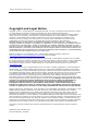
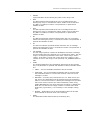
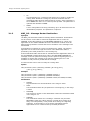
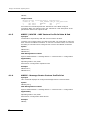
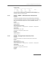
Dialogic ® DSI SS7G41 Signaling Server Introduction to Message Router Functionality www.dialogic.com Dialogic® DSI SS7G41 Signaling Server Copyright and Legal Notice Copyright © 2012 - 2014 Dialogic Inc. All Rights Reserved. You may not reproduce this document in whole or in part without permission in writing from Dialogic Inc. at the address provided below. All contents of this document are furnished for informational use only and are subject to change without notice and do not represent a commitment on the part of Dialogic Inc. and its affiliates or subsidiaries (“Dialogic”). Reasonable effort is made to ensure the accuracy of the information contained in the document. However, Dialogic does not warrant the accuracy of this information and cannot accept responsibility for errors, inaccuracies or omissions that may be contained in this document. INFORMATION IN THIS DOCUMENT IS PROVIDED IN CONNECTION WITH DIALOGIC ® PRODUCTS. NO LICENSE, EXPRESS OR IMPLIED, BY ESTOPPEL OR OTHERWISE, TO ANY INTELLECTUAL PROPERTY RIGHTS IS GRANTED BY THIS DOCUMENT. EXCEPT AS PROVIDED IN A SIGNED AGREEMENT BETWEEN YOU AND DIALOGIC, DIALOGIC ASSUMES NO LIABILITY WHATSOEVER, AND DIALOGIC DISCLAIMS ANY EXPRESS OR IMPLIED WARRANTY, RELATING TO SALE AND/OR USE OF DIALOGIC PRODUCTS INCLUDING LIABILITY OR WARRANTIES RELATING TO FITNESS FOR A PARTICULAR PURPOSE, MERCHANTABILITY, OR INFRINGEMENT OF ANY INTELLECTUAL PROPERTY RIGHT OF A THIRD PARTY. Dialogic products are not intended for use in certain safety-affecting situations. Please see http://www.dialogic.com/company/terms-ofuse.aspx for more details. Due to differing national regulations and approval requirements, certain Dialogic products may be suitable for use only in specific countries, and thus may not function properly in other countries. You are responsible for ensuring that your use of such products occurs only in the countries where such use is suitable. For information on specific products, contact Dialogic Inc. at the address indicated below or on the web at www.dialogic.com. It is possible that the use or implementation of any one of the concepts, applications, or ideas described in this document, in marketing collateral produced by or on web pages maintained by Dialogic may infringe one or more patents or other intellectual property rights owned by third parties. Dialogic does not provide any intellectual property licenses with the sale of Dialogic products other than a license to use such product in accordance with intellectual property owned or validly licensed by Dialogic and no such licenses are provided except pursuant to a signed agreement with Dialogic. More detailed information about such intellectual property is available from Dialogic’s legal department at 6700 de la Cote-de-Liesse Road, Suite 100, Borough of Saint-Laurent, Montreal, Quebec, Canada H4T 2B5. Dialogic encourages all users of its products to procure all necessary intellectual property licenses required to implement any concepts or applications and does not condone or encourage any intellectual property infringement and disclaims any responsibility related thereto. These intellectual property licenses may differ from country to country and it is the responsibility of those who develop the concepts or applications to be aware of and comply with different national license requirements. Dialogic, Dialogic Pro, Dialogic Blue, Veraz, Brooktrout, Diva, BorderNet, PowerMedia, ControlSwitch, I-Gate, Mobile Experience Matters, Network Fuel, Video is the New Voice, Making Innovation Thrive, Diastar, Cantata, TruFax, SwitchKit, Eiconcard, NMS Communications, SIPcontrol, Exnet, EXS, Vision, inCloud9, NaturalAccess and Shiva, among others as well as related logos, are either registered trademarks or trademarks of Dialogic Inc. and its affiliates or subsidiaries. Dialogic’s trademarks may be used publicly only with permission from Dialogic. Such permission may only be granted by Dialogic’s legal department at 6700 de la Cote-de-Liesse Road, Suite 100, Borough of Saint-Laurent, Montreal, Quebec, Canada H4T 2B5. Any authorized use of Dialogic’s trademarks will be subject to full respect of the trademark guidelines published by Dialogic from time to time and any use of Dialogic’s trademarks requires proper acknowledgement. The names of actual companies and products mentioned herein are the trademarks of their respective owners. Publication Date: October 2014 Document Number: U04LGD 2 Introduction to Message Router Functionality Issue 2 Revision History Issue Date 2 October 2014 1 September 2012 Note: Description Updated for use with Revision 2.x software Initial Release The current version of this document can be found at: http://www.dialogic.com/support/helpweb/signaling Contents Revision History ........................................................................................................... 3 1 Introduction ........................................................................................................ 4 2 Message Router Architecture .............................................................................. 5 2.1 2.2 2.3 Domains ................................................................................................................................ 5 Message Routing Model ........................................................................................................... 5 Status Routing Model (Concerned Entities) ................................................................................. 8 3 Configuration ...................................................................................................... 9 3.1 Message Router Configuration Commands .................................................................................. 9 3.1.1 MRF_OG – Message Router Origin................................................................................. 9 3.1.2 MRF_RK – Message Router Routing Key....................................................................... 10 3.1.3 MRF_DE – Message Router Destination ........................................................................ 12 3.1.4 MRF_CE – Message Router Concerned Entity ................................................................ 13 3.1.5 MRF_CP – Message Router Custom Profile ................................................................... 15 SIGTRAN Gateway Configuration ............................................................................................ 16 3.2.1 TDM Network Configuration ....................................................................................... 16 3.2.2 M3UA Application Server Configuration ........................................................................ 16 3.2.3 Message Router Configuration .................................................................................... 17 Impact on other Configuration Commands ............................................................................... 17 3.3.1 MTP_CONFIG – MTP Configuration .............................................................................. 17 3.3.2 SCCP_CONFIG – SCCP Configuration ........................................................................... 18 3.3.3 Optional Host Deactivation......................................................................................... 18 3.3.4 Activation of Message Router tracing ........................................................................... 18 3.2 3.3 4 MMI Commands ................................................................................................. 19 4.1 Message Router Configuration Commands ................................................................................ 19 4.1.1 MRCEI / MRCEE – MRF Concerned Entity Initiate & End ................................................. 19 4.1.2 MRCEP - Message Router Concerned Entity Print .......................................................... 19 4.1.3 MRCPI / MRCPE – MRF Custom Profile Initiate & End ..................................................... 20 4.1.4 MRCPP - Message Router Custom Profile Print .............................................................. 20 4.1.5 MRDEI / MRDEE – MRF Destination Initiate & End ......................................................... 21 4.1.6 MRDEP - Message Router Destination Print .................................................................. 21 4.1.7 MROGI / MROGE – MRF Origin Initiate & End ............................................................... 22 4.1.8 MROGP - Message Router Origin Print ......................................................................... 22 4.1.9 MRRKI / MRRKE- MRF Routing Key Initiate & End ......................................................... 23 4.1.10 MRRKP - Message Router Routing Key Print ................................................................. 23 Message Router Measurement Commands ............................................................................... 25 4.2.1 MSDEP - Message Router Destination Measurements .................................................... 25 4.2.2 MSOGP - Message Router Origin Measurements ........................................................... 25 4.2.3 MSRKP - Message Router Routing Key Measurements ................................................... 26 4.2 5 Worked Configuration Example ......................................................................... 28 5.1 Conventional SIGTRAN Gateway (M3UA to TDM) ....................................................................... 28 3 Dialogic® DSI SS7G41 Signaling Server 1 Introduction The Message Router and SIGTRAN Gateway capabilities that form part of the Dialogic® DSI SS7G41 Signaling Server allow significant flexibility in the way messages and status are passed through the server and allow the unit to act as SIGTRAN Gateway located between an Application Server and a TDM network. This document supplements the released User Documentation and describes the capabilities and architecture of the Message Router functionality; it defines the specific commands used and provides example configurations demonstrating some common scenarios. The Message Router provides the ability to flexibly route messages between the Network Domain (MTP or M3UA), User Parts and SIGTRAN Application Servers using M3UA. The routing is based on the MTP routing label and allows messages from a specific Origin to use individual Routing Keys to selectively match routing label parameters and determine which Destination to be sent towards. The Message Router can be configured to act as a SIGTRAN Signaling Gateway or Gateway Signaling transfer Point (STP). The Signaling server can also behave as an SCCP Router by configuring the Message Router to send traffic through the local SCCP for Global Title Translation. The Message Router capability is applicable to SS7G41-SIU and SS7G41-SWS without requiring any additional licenses. Message Router and SIGTRAN Gateway functionality can co-exist with existing SIU operation and the SIU can be used either with or without Hosts. See Figure 1 for an overview of the routing capabilities. Message to a Local User Part on the Signaling Server (e.g ISUP or SCCP). Message from a Local User Part on the Signaling Server (e.g ISUP or SCCP). Message from a Remote Application Server Message Router Message from a SS7 or SIGTRAN network Figure 1 Message Routing Overview 4 Message to a Remote Application Server Message to a SS7 or SIGTRAN network Introduction to Message Router Functionality Issue 2 2 Message Router Architecture 2.1 Domains The Message Router routes traffic between three DOMAINs: The Network domain which may be an MTP network (running over MTP2 or M2PA) or a SIGTRAN M3UA network were the Signaling Server is connected to an M3UA SIGTRAN Gateway or using M3UA IPSP for peer to peer communication. The Application Server domain where the Signaling Server is acting as an M3UA Signaling Gateway and is connected to an Application Server. The User Part domain where the User Part is either running on the Signaling Server (eg SCCP, ISUP or BICC) or running as a userprovided application running on an SIU host. In each of these domains traffic can be further subdivided by Network Context (representing different networks), Originating Point Code (OPC) and Service Indicator (representing different User Parts) where a Service Indicator of 3 identifies SCCP, a Service Indicator of 5 identifies ISUP and a Service Indicator of 13 identifies the traffic as BICC. 2.2 Message Routing Model The Message Router has three Routing Components; Origin, Routing Key and Destination. Together these components allow the user to configure how traffic flows through the Signaling Server. Message Router Origin – An Origin identifies how the traffic arrives on the Signaling Server. It is defined by DOMAIN (NETWORK, AS or UPART), Network Context, Service Indicator and optionally Originating Point Code. Traffic arriving from this source will be analyzed against a table of Routing Keys to determine how it should be routed. Potentially each Origin may use a different table of Routing Keys. Message Router Routing Key – A Routing Key specifies values for each of the fields in the message Routing Label (eg. OPC, DPC, Network Indicator, Service Indicator and CIC range) and an identifier indicating which Destination should be used for messages that match the Routing Key. The Routing Key values are compared with those in the received message until a match is found at which point the Destination is used (in conjunction with an optional HUNT algorithm) to determine where the message is sent. Message Router Destination – A Destination specifies a Domain, a Network Context, an optional Destination Point Code and (for the Application Server domain) an Application Server to which the message should be sent. Multiple Destinations may be contained within the same table; in this case the current accessibility of the destination is used in conjunction with the Hunt algorithm to determine which destination to use. If no Destination is accessible, for dual server configurations the message will be passed to the partner unit, to see if it can route the message to a destination. 5 Dialogic® DSI SS7G41 Signaling Server At each stage of processing (Origin, Routing Key and Destination) the option exists for any parameters in the Routing Label to be modified. This is achieved by configuring a Custom Profile which details new values for any Routing Label parameters that are to be replaced. The Custom Profile can be associated with the Origin, Routing Key or Destination. Measurements of traffic passing through each state of the Message Router are automatically captured and accessible to the user. Message tracing can optionally be enabled for diagnostic purposes to log all messages as they pass through the Message Router. In addition any messages that are unable to be routed (either due to an inaccessible destination or invalid routing configuration) are automatically logged as selective traces to the trace log. The following figure illustrates the flow of a message as it passes through the Message Router. 6 Introduction to Message Router Functionality Issue 2 SI NI OPC Message DPC SLS CIC (Calls) ORIGIN Operation Based on how the message arrived and the Service Indicator contained within the message a table of Routing Keys (RKTAB) is selected. Origin Parameters DOMAIN NC OPC SI TYPE (Calls) Post Operation Once a Routing Key table (RKTAB) has been selected a Custom Profile (CP) may be applied to modify individual parameters in the routing label prior to searching the table. RKTAB Routing Key Parameters Operation OPC Post Operation Routing Label parameters are compared with those contained within each Routing Key until a match is found. At this point the Destination table (DEST) and optional Hunting Algorithm (HUNT) is selected for message routing. DPC NI SI CIC_RANGE The Hunting Algorithm (HUNT) associated with routing key entry selected will be used to search the selected destination table. Once a Destination table (DEST) has been selected a Custom Profile (CP) may be applied to modify the routing label prior to searching the table. DEST Destination Parameters Operation RAS Post Operation Using the Hunting Algorithm (HUNT) search the Destination Table for the next available destination. For Destinations in the AS domain availability is determined by status of the associated RAS. For Destinations in the NETWORK domain availability is determined either by the availability of the optional DPC configured for the DESTID or by the availability of the DPC contained within the message (for the Network Context from the DESTID). UPART destinations are always considered available. If there are no rows available in the destination table the original message will be passed onto the partner Signaling Server (if applicable) for routing. DPC DOMAIN NC SI NI OPC Message DPC SLS CIC (Calls) Once the destination row has been selected a Custom Profile (CP) may be applied to modify the routing label prior to transmission to the destination.. TYPE (Calls) Figure 2: Message Routing Function. 7 Dialogic® DSI SS7G41 Signaling Server 2.3 Status Routing Model (Concerned Entities) In addition to routing messages, the Message Router allows for the maintenance and mapping of point code status across the Signaling Server. The Message Router is able to respond to Signaling Route Set Test and SIGTRAN Destination Audit messages and generate the appropriate Route Status messages (eg Transfer Allowed/Transfer Prohibited and SIGTRAN Destination Available/Unavailable) to adjacent for Point Codes. To preserve operating flexibility, the user must explicitly configure the identity of nodes that are concerned about the status of other nodes within the network. This is achieved using the concept of Concerned Entities. For any DPC and Network Context combination the user can specify a list of ‘concerned’ entities that need to be notified of status changes. The types of relationship are AS, NETWORK and UPART and they operate as follows: AS - The Concerned Entity is a Remote Application Server (RAS) in the AS domain connected using M3UA that will be updated using DAVA/DUNA messages whenever the status of the DPC changes. NETWORK - The Concerned Entity is an adjacent Destination Point Code (DPC) in the NETWORK domain that will be updated using the appropriate route status messages whenever the status of DPC changes. The Concerned Entity may be in an MTP network (running over MTP2 or M2PA) or in a SIGTRAN M3UA network were the Signaling Server is connected to an M3UA SIGTRAN Gateway or in an M3UA network using M3UA IPSP for peer to peer communication UPART - The Concerned Entity is a local protocol module on the Signaling Server (or SIU host) in the UPART domain that will be updated using MTP-PAUSE/MTP-RESUME indications whenever the status of DPC changes. Optionally each Concerned Entity may be configured with an Alias which is used instead of the actual DPC in the notification. 8 Introduction to Message Router Functionality Issue 2 3 Configuration 3.1 Message Router Configuration Commands Operation of the Message Router is configured using the commands defined in this section in the config.txt protocol configuration file. All configuration commands are entered in coma separated format with both the parameter and the value being explicitly specified in the command. Parameters can be entered in any order and optional parameters can be omitted. For example: MRF_OG:OGID=1,DOMAIN=NETWORK,SI=5,RKTAB=1; 3.1.1 MRF_OG – Message Router Origin Synopsis The MRF_OG command initiates a Message Router Origin. An Origin identifies the point from which an incoming message is received. An Origin is specified by the DOMAIN (Application Server, Network or User Part), Network Context, Service Indicator and optionally Originating Point Code. Each origin must be assigned a Routing Key table identifier to indicate which set of Routing Keys should be applied. Optionally a Custom Profile may be assigned for manipulating parameters in the Routing Label. When a Custom Profile is assigned to an Origin the parameter manipulation occurs before the parameters are compared with the Routing Key. The Origin has its own unique identifier (OGID) and can optionally be assigned a text based label (LABEL) to assist with identification. If the DOMAIN is NETWORK or AS then all traffic for the associated Service Indicator will be processed by the Message Router rather than being passed directly to ISUP or SCCP (or a user module on a host configured by the MTP_USER_PART command). If the DOMAIN is UPART, then all outgoing messages from the User Part (eg ISUP or SCCP) will be processed by the Message Router rather than being transmitted directly to the network. Syntax MRF_OG:[NC=NC0],OGID=,DOMAIN=,RKTAB=,SI=[,OPC=ANY][,CP=NONE][,LABEL=] ; Example MRF_OG:OGID=1,DOMAIN=NETWORK,SI=5,RKTAB=1; MRF_OG:NC=NC0,OGID=2,DOMAIN=AS,SI=5,RKTAB=1,CP=NONE; MRF_OG:OGID=3,NC=NC0,DOMAIN=USER,SI=3,RKTAB=2,CP=1; Parameters NC SS7 Network Context. This parameter identifies the SS7 Network Context associated with the Origin. Supported values are: NC0, NC1, NC2 or NC3. When the parameter omitted, a value of NC0 is assumed. 9 Dialogic® DSI SS7G41 Signaling Server 3.1.2 OGID Logical identifier for the Origin. A number in the range 0-4095. DOMAIN The domain a message is being received from. A domain may be either NETWORK (either the MTP network or M3UA when connected to a Signaling Gateway), User Part (UPART) or AS (M3UA when connected to an Application Server). SI Service Indicator in the range 0-15. Received messages containing the configured SI will be considered to match the Origin. If required a different Origin may be configured for each SI. OPC Originating Point Code. Received messages containing the configured OPC will be considered to match the Origin. The parameter is optional and defaults to ANY. RKTAB Logical Identifier for the table of Routing Keys associated with this Origin. A number in the range 0-49. CP Logical identifier for a custom profile that may be used to modify the routing label AFTER the routing table has been determined for routing. If the parameter is omitted or set to NONE then there is no custom profile present. The parameter is optional and defaults to NONE. LABEL A user configurable text string containing up to 32 characters used for identification purposes. The parameter is optional. MRF_RK – Message Router Routing Key Synopsis The MRF_RK command initiates a Message Router Routing Key. Routing Keys are used to filter messages by matching the individual Routing Label fields from the received message with those contained in the Routing Key to determine the appropriate Destination. Each Routing Key belongs to a table (identified by the RKTAB parameter) which must be specified for each Origin that needs to use the Routing Key. Syntax MRF_RK:RKI=,RKTAB=,[OPC=,][DPC=,][SI=,][NI=,][CIC_RANGE=,] [HUNT=,]DEST=,[CP=,][LABEL=,] Example MRF_RK:RKI=1,RKTAB=1,SI=3,DEST=1; MRF_RK:RKI=2,RKTAB=1,OPC=ANY,DPC=ANY,SI=5,,HUNT=SINGLE,DEST=1; MRF_RK:RKI=2,RKTAB=2,SI=3,DEST=2,LABEL=London; MRF_RK:RKI=4,RKTAB=2,OPC=43434,DPC=44343,SI=5,CIC_RANGE=1-2000, HUNT=IAM,DEST=1; Parameters 10 RKI A Routing Key Index in the range 0-4095 used to uniquely identify a particular Routing Key. Introduction to Message Router Functionality Issue 2 RKTAB Logical Identifier of the Routing Key table in the range 0-49. OPC The OPC specified should match the one in message before the Routing Key entry is considered a match. If OPC is set to ANY then any OPC is considered a match. The parameter is optional and defaults to ANY. DPC The DPC specified should match the one in message before the Routing Key entry is considered a match. If DPC is set to ANY then any OPC is considered a match. The parameter is optional and defaults to ANY. NI The Network Indicator specified should match the one in message before the Routing Key entry is considered a match. The parameter is optional and defaults to ANY. SI The Service Indicator specified should match the one in message before the Routing Key entry is considered a match. The parameter is optional and defaults to ANY. CIC_RANGE The CIC range specifies a subset of ISUP/BICC CICs that a message should contain before the Routing Key is considered a match. The CIC range is a compound parameter of the form <base-range> where <base> is the base (or first) CIC in the range and <range> is the number of CICs in the range. If not specified, CIC_RANGE defaults to ANY. HUNT The Hunting Method for the Destination determined by the Routing Key. The parameter is optional and defaults to FIRST. Possible values are: FIRST – The first available Destination will be selected. CIRCULAR – The next available Destination will be selected from the Destination table in a round robin manner each time a new message is routed. BALANCE – Currently only valid for SI=5 or 13. Each time a new call arrives, the Destination will be selected from the Destination table in a round robin manner. Subsequent messages for the same call/circuit will be routed to the same Destination. When using HUNT=BALANCE the CIC range should be specified, by default the Base CIC is 0 and the CIC range is 4096. To include more than 4096 CICs (eg for BICC), it is necessary to use multiple routing keys. SHARE1 - Destination rows in the destination table will be load shared based on the SLS value in the message. DEST The Destination table determined by the Routing Key 11 Dialogic® DSI SS7G41 Signaling Server 3.1.3 CP Logical identifier for a custom profile that may be used to modify the routing label AFTER the routing key has been matched and the destination table has been determined for routing. If the parameter is set to NONE then there is no custom profile present. The parameter is optional and defaults to NONE. LABEL A user configurable text string containing up to 32 characters used for identification purposes. The parameter is optional. MRF_DE – Message Router Destination Synopsis The MRF_DE command initiates a Message Route Destination. Destinations can be used to route traffic to a Remote Application Server in the AS DOMAIN, to the SS7 Network in the NETWORK DOMAIN or to a local user application in the UPART DOMAIN where the destination module id will be determined by Network Context and Service Indicator in the message to be transmitted A Destination is selected as a result of a Routing Key match. The hunting algorithm use to search through the entries in the destination table is specified by the HUNT parameter in the Routing Key. If the Destination table cannot find an available Remote Application Server in the AS DOMAIN or Destination Point Code in the NETWORK DOMAIN the message router will pass the message onto the partner Signaling Server, if available or discard the message if the partner Signaling Server is not available or had previously forwarded the message. A Custom Profile can be set to modify the routing label. Syntax MRF_DE:DESTID=,DEST=,DESTSEQ=,DOMAIN=[,NC=NC0][,RAS=] [,DPC=][,CP=][,LABEL=]; Example MRF_DE:DESTID=1,DEST=1,DESTSEQ=1,DOMAIN=AS,RAS=1; MRF_DE:DESTID=2,DEST=2,DESTSEQ=2,DOMAIN=NETWORK; MRF_DE:DESTID=3,DEST=3,DESTSEQ=3,DOMAIN=UPART,RAS=NONE,CP=NONE; Parameters 12 DESTID Logical identifier for the Destination in the range 0-4095. DEST The Destination table ID (as specified in a Routing Key) in the range 0-4095. DESTSEQ The sequence number of this Destination within the Destination table in the range 0-31. DOMAIN The destination domain for a message. A domain may be either NETWORK (either the a MTP network or M3UA when acting as an ASP), User Part(UPART) or AS (M3UA when acting as a Signaling Gateway). If the domain is set to AS the associated Remote Application Server is determined by the RAS parameter. Introduction to Message Router Functionality Issue 2 3.1.4 NC SS7 Network Context. This parameter identifies the SS7 network messages will be sent to. Supported values are: NC0, NC1, NC2 or NC3. When the parameter is not present, a value of NC0 is assumed. RAS The destination Remote Application Server to which messages will be sent. This parameter is used only when DOMAIN=AS. The Remote Application Server associated with a Destination must be configured to be acting as a Local Signaling Gateway. DPC Destination Point Code. If present, the status of the configured DPC will be checked and the table row will only be selected if the DPC is available. If available, this DPC will be copied into the routing label of the message. CP Logical identifier for a custom profile that may be used to modify the routing label AFTER the row in the destination table has been selected for routing. If the parameter is set to NONE then there is no custom profile present. The parameter is optional and will default to NONE. LABEL A user configurable text string containing up to 32 characters used for identification purposes. The parameter is optional. MRF_CE – Message Router Concerned Entity Synopsis The MRF_CE command defines a Concerned Entity defines entities that need to be notified in the event of the accessibility of the DPC changing. Syntax MRF_CE:[NC=NC0,]CONCID=,DPC=,CONC_DOMAIN=[,CONC_NC=],CONC_ENT=[,ALIAS=]; Example MRF_CE: CONCID=1,DPC=2322,CONC_DOMAIN=NETWORK,CONC_ENT=256; MRF_CE:NC=NC0,CONCID=2,DPC=653,CONC_DOMAIN=AS,CONC_NC=NC0,CONC_ENT=1; Parameters NC SS7 Network Context. This parameter identifies the SS7 network in which the Destination Point Code exists. Supported values are: NC0, NC1, NC2 or NC3. Defaults to NC0 if not specified. CONCID Logical identifier for the concerned relationship in the range 0-4095. 13 Dialogic® DSI SS7G41 Signaling Server DPC The Destination Point Code who’s status the concerned point code needs to be informed about. If set to ANY the Concerned Point Code will be concerned about all point codes in the network context. If explicitly configured, the DPC must have already been configured as one of the following: A DPC associated with an MTP Route, A DPC associated with a SIGTRAN Route, A DPC associated with a SIGTRAN Remote Application Server, An OPC associated with an MTP Link Set, or an OPC associated with a SIGTRAN Local Application Server. CONC_DOMAIN The Concerned Domain that is to be notified of the change in status. Possible values are: o AS The Concerned Entity is an Application Server which has been configured as a SIGTRAN Remote Application Server. o NETWORK The Concerned Entity is an Adjacent Point Code in the NETWORK domain. o UPART The Concerned Entity is a User Part (identified by Service Indicator). The User Part associated with the Service Indicator should already be specified on a routing origin command. CONC_NC The Network Context in which the Concerned Entity exists. For ASP entities it must be the same NC as that used on the ASLINK. If not specified, CONC_NC defaults to the same value as NC. CONC_ENT The Concerned Entity which is a reference to a specific entity in the Concerned Domain which will be informed of the change in status of the DPC. If CONC_DOMAIN=NETWORK then CONC_ENT is the adjacent point code that needs to be notified. If set to ANY then all point codes in the CONC_NC will be informed. If CONC_DOMAIN=AS then CONC_ENT is the Remote Application Server (RAS) that is concerned about the status of the DPC. If set to ANY then all Remote Application Servers in the CONC_NC will be informed. If CONC_DOMAIN=UPART then CONC_ENT is the Service Indicator (SI). 14 ALIAS An Alias for the Destination Point Code that will be presented to the affected entity as the Point Code that has changed state. NONE or Number from 0 to 16777215. An Alias Point Code may be used for example when a change in state for a particular point code in one network should be represented as a change in state for a point code that exists in a different network. If an Alias point code is specified the DPC must be explicitly defined. ALIAS defaults to NONE if not specified. Introduction to Message Router Functionality Issue 2 3.1.5 MRF_CP – Message Router Custom Profile Synopsis The MRF_CP command initiates a Custom Profile which can be used by an Origin, Routing Key or Destination to modify the routing label of messages passing through the Message Router. Syntax MRF_CP:CP=[,OPC=][,DPC=][,NI=][,SI=],[LABEL=]; Example MRF_CP:CP=1,OPC=1423,DPC=2322; Parameters CP Logical identifier for the custom profile in the range 0-4095. OPC If the value is not ‘NONE’ then the OPC specified will replaced the OPC in the message the profile is being applied to. This parameter is optional and defaults to NONE. DPC If the value is not ‘NONE’ then the DPC specified will replaced the DPC in the message the profile is being applied to. This parameter is optional and defaults to NONE. NI If the value is not ‘NONE’ then the Network Indicator specified will replaced the Network Indicator in the message the profile is being applied to. This parameter is optional and defaults to NONE. SI If the value is not ‘NONE’ then the Service Indicator specified will replaced the Service Indicator in the message the profile is being applied to. This parameter is optional and defaults to NONE. LABEL A user configurable text string containing up to 32 characters used for identification purposes. The parameter is optional. 15 Dialogic® DSI SS7G41 Signaling Server 3.2 SIGTRAN Gateway Configuration This section summarizes the main configuration steps to configure a conventional SIGTRAN Signaling Gateway where the Signaling Server sits between one or more Application Servers and a TDM based network. A full example configuration is shown in Section 5.1. The Application Servers communicate using M3UA with the Signaling Server which acts as a Signaling Gateway. The flexible message routing function and features of the Signaling Server make it suitable for a number of more complex network configurations but these are beyond the scope of this document. The three stages to configuring a conventional SIGTRAN Signaling Gateway are as follows: a) Configure the TDM Network domain b) Configure the M3UA Application Server domain c) Configure the Message Router to connect between the two domains 3.2.1 TDM Network Configuration For use as a SIGTRAN Signaling Gateway the TDM network is configured in the usual manner. The Signaling Server supports stand-alone and dual configurations. 3.2.2 M3UA Application Server Configuration When operating as a conventional SIGTRAN Gateway, the Signaling Server acts as a Signaling Gateway Process and connects using M3UA to the Application Server (this is referred to as a Remote Application Server (RAS) when configuring the Signaling Server). When configuring the SIGTRAN Link, using the STN_LINK command, options bit 4 should be set to 1 (to indicate the Signaling Server is acting as a Signaling Gateway Process). Bit 4 of the STN_LINK options is defined as follows: Bit 4 – When set to zero the Signaling Server end of the link is acting as an Application Server Process. When set to one the Signaling Server is acting as a Signaling Gateway (in which case bit 2 of the options must be set to zero). When configuring the SIGTRAN Remote Application Server, using the STN_RAS command, options bit 3 should be set (to indicate the Signaling Server is acting as a Signaling Gateway). Bits 2 and 3 of the STN_RAS options are now defined as follows: Bit 2 – When set to zero will consider a point code on Remote Application Servers to be unavailable if any of the Remote Application Servers have failed. When set to one will consider a point code available if any of the Remote Application Servers is in service Bit 3 – When set to zero the Signaling Server is acting in an IPSP relationship with the Remote Application Server. When set to one the Signaling Server is acting as a Signaling Gateway for the Remote Application Server. 16 Introduction to Message Router Functionality Issue 2 3.2.3 Message Router Configuration Once the TDM Network and the M3UA Application Server have been configured the Message Router can be configured. This happens in four stages: a) Configure the Origin for both Network and Application Server domain, b) Configure the Destination for both Network and Application Server domain, c) Configure Routing Keys, d) Configure any Concerned Entities The following example illustrates this configuration sequence using a minimal set of configuration commands and intentionally avoids using advanced options. ******************** * Configure Message Router Origins: * MRF_OG:[NC=,]OGID=,DOMAIN=,SI=,RKTAB=,[CP=,][LABEL=,]; * MRF_OG:OGID=1,DOMAIN=NETWORK,SI=5,RKTAB=1,LABEL=FromNetwork; MRF_OG:OGID=2,DOMAIN=AS,SI=5,RKTAB=2,LABEL=FromAppServer; * ****** * Configure Message Router Destinations: * MRF_DE:DESTID=,DEST=,DESTSEQ=,DOMAIN=,[NC=,][RAS=,][CP=,][LABEL=,] * MRF_DE:DESTID=1,DEST=1,DESTSEQ=1,DOMAIN=NETWORK,LABEL=ToNetwork; MRF_DE:DESTID=2,DEST=2,DESTSEQ=1,DOMAIN=AS,RAS=1,LABEL=ToAppServer; * ****** * Configure Routing Keys: * MRF_RK:RKI=,RKTAB=,[OPC=,][DPC=,][SI=,][NI=,] * [CIC_RANGE=,][HUNT=,]DEST=,[CP=,][LABEL=,] * MRF_RK:RKI=1,RKTAB=1,DEST=2,LABEL=NetworkToAppServer; MRF_RK:RKI=2,RKTAB=2,DEST=1,LABEL=AppServerToNetwork; * ****** * Configure Concerned Entities: * MRF_CE:[NC=,]CONCID=,DPC=,CONC_DOMAIN=, * [CONC_NC=,]CONC_ENT=,[ALIAS=,]; * MRF_CE:CONCID=1,DPC=ANY,CONC_DOMAIN=AS,CONC_ENT=1; * ******************** 3.3 Impact on other Configuration Commands When the first Message Router Origin is configured the Signaling Server detects that Message Router functionality is in use and automatically sets certain configuration options to specific values. This section lists the affected options: 3.3.1 MTP_CONFIG – MTP Configuration When a Message Router Origin for a particular Network Context is configured in the NETWORK domain Bit 0, Bit 17 and Bit 22 of the options parameter for any associated MTP_CONFIG commands will automatically be set. These bits controls how received Route Set Test, Transfer Controlled and Signaling Route Set Congestion Messages that are not destined for the MTP local point code are processed and are set to allow the Message Router to correctly processing these messages for the domains and Network Contexts under its control. 17 Dialogic® DSI SS7G41 Signaling Server 3.3.2 SCCP_CONFIG – SCCP Configuration When a Message Router Origin for a particular Network Context is configured in the UPART domain with a service indicator of 3 and a user configures SCCP on the Signaling Server in that Network Context bit 2 of the <options2> parameter in any SCCP_CONFIG commands will automatically be set. Setting this bit allows the Message Routing functionality to understand the point code format of messages transmitted by SCCP. 3.3.3 Optional Host Deactivation Message Router functionality can co-exist with conventional SIU Hosts. However, in deployments where there are no SIU Hosts it is necessary to explicitly disable SIU Hosts (otherwise network facing SS7 links will get taken out of service). This is achieved using the SIU_HOSTS command in config.txt and setting the NUM_HOSTS parameter to zero as follows: SIU_HOSTS:NUM_HOSTS=0; 3.3.4 Activation of Message Router tracing To activate message tracing for messages passing through the Message Router the following command should be used: CNTMS:MODULE=MRF,ACTIVE=Y; 18 Introduction to Message Router Functionality Issue 2 4 MMI Commands The following commands, available via the MMI command line or Web Management Interface, allow the user to display Message Routing configuration, support dynamic additional and remote of components and provide measurements of the traffic flow through the Message Router. 4.1 4.1.1 Message Router Configuration Commands MRCEI / MRCEE – MRF Concerned Entity Initiate & End Synopsis Commands to dynamically add and remove Concerned Entities. To add a new Concerned Entity, first add a new MRF_CE command to config.txt then execute the MRCEI command. To remove a Concerned Entity, first remove the MRF_CE command from config.txt then execute the MRCEE command. Syntax MRCEI:CONCID=; MRCEE:CONCID=; Web Management Location System Administration > Message Router > Concerned Entity > Configuration Applicability Operating Modes: SIU, SWS Permissions: Configuration Update Access Prerequisites A value of ANY cannot be used for a DPC when dynamically adding a new Concerned Entity. Example MRCEI:CONCID=1; MRCEE:CONCID=1; 4.1.2 MRCEP - Message Router Concerned Entity Print Synopsis This command displays configured Message Router Concerned Entities. Syntax MRCEP:[CONCID=]; Web Management Location System Administration > Message Router > Concerned Entity > Configuration Applicability Operating Modes: SIU, SWS Permissions: Configuration Read Access Example 19 Dialogic® DSI SS7G41 Signaling Server MRCEP; Output format Message Router Concerned Entity Configuration CONCID NC DPC CONC_DOMAIN CONC_NC CONC_ENT ALIAS 0 NC0 43434 NETWORK NC0 2332 1 NC0 13233 AS NC0 5 See either the individual parameter definitions or the MML config.txt command "MRF_CE" defined in the user manual for a full description of the parameters used in the output format. 4.1.3 MRCPI / MRCPE – MRF Custom Profile Initiate & End Synopsis Commands to dynamically add and remove Custom Profiles. To add a new Custom Profile, first add a new MRF_CP command to config.txt then execute the MRCPI command. To remove a Custom Profile, first remove the MRF_CP command from config.txt then execute the MRCPE command. Syntax MRCPI:CP=; MRCPE:CP=; Web Management Location System Administration > Message Router > Custom Profile > Configuration Applicability Operating Modes: SIU, SWS Permissions: Configuration Update Access Example MRCPI:CP=1; MRCPE:CP=1; 4.1.4 MRCPP - Message Router Custom Profile Print Synopsis This command displays all configured Message Router Custom Profiles. Syntax MRCPP:[CP=]; Web Management Location System Administration > Message Router > Custom Profile > Configuration Applicability Operating Modes: SIU, SWS Permissions: Configuration Read Access Example MRCPP; 20 Introduction to Message Router Functionality Issue 2 Output format Message Router CP OPC 0 NONE 1 123233 Custom Profile Configuration DPC NI SI 2332 0 NONE NONE NONE NONE LABEL See either the individual parameter definitions or the MML config.txt command "MRF_CP" defined in the user manual for a full description of the parameters used in the output format. 4.1.5 MRDEI / MRDEE – MRF Destination Initiate & End Synopsis Commands to dynamically add and remove Message Router Destinations. To add a new Destination, first add a new MRF_DE command to config.txt then execute the MRDEI command. To remove a Destination, first remove the MRF_DE command from config.txt then execute the MRDEE command. Syntax MRDEI:DESTID=; MRDEE:DESTID=; Web Management Location System Administration > Message Router > Destination > Configuration Applicability Operating Modes: SIU, SWS Permissions: Configuration Update Access Example MRDEI:DESTID=1; MRDEE:DESTID=1; 4.1.6 MRDEP - Message Router Destination Print Synopsis This command displays all configured Message Router Destinations. Syntax MRDEP:[DESTID=]; Web Management Location System Administration > Message Router > Destination > Configuration Applicability Operating Modes: SIU, SWS Permissions: Configuration Read Access Example MRDEP; 21 Dialogic® DSI SS7G41 Signaling Server Output format Message Router DESTID DEST 0 1 1 2 Destination Configuration DESTSEQ NC DOMAIN RAS 1 NC0 AS 1 1 NC0 NETWORK NONE CP LABEL 1 See either the individual parameter definitions or the MML config.txt command "MRF_DE" defined in the user manual for a full description of the parameters used in the output format. 4.1.7 MROGI / MROGE – MRF Origin Initiate & End Synopsis Commands to dynamically add and remove Message Router Origins. To add a new Origin, first add a new MRF_OG command to config.txt then execute the MROGI command. To remove an Origin, first remove the MRF_OG command from config.txt then execute the MROGE command. Syntax MROGI:OGID=; MROGE:OGID=; Web Management Location System Administration > Message Router > Concerned Entity > Configuration Applicability Operating Modes: SIU, SWS Permissions: Configuration Update Access Prerequisites To dynamically add Origins, there must already be at least one active origin that uses the same NC / DOMAIN / SI combination. Likewise it is not possible to dynamically remove the last Origin using a specific NC / DOMAIN / SI combination. Example MROGI:OGID=1; MROGE:OGID=1; 4.1.8 MROGP - Message Router Origin Print Synopsis This command displays all configured Message Router Origins. Syntax MROGP:[OGID=]; Web Management Location System Administration > Message Router > Origin > Configuration Applicability Operating Modes: SIU, SWS Permissions: Configuration Read Access Example 22 Introduction to Message Router Functionality Issue 2 MROGP; Output format Message Router Origin OGID NC DOMAIN RKTAB 0 NC0 M3UA 1 1 NC0 MTP 1 Configuration SI CP 3 NONE 3 1 LABEL See either the individual parameter definitions or the MML config.txt command "MRF_OG" defined in the user manual for a full description of the parameters used in the output format. 4.1.9 MRRKI / MRRKE- MRF Routing Key Initiate & End Synopsis Commands to dynamically add and remove Message Router Routing Keys. To add a new Routing Key, first add a new MRF_RK command to config.txt then execute the MRRKI command. To remove a Routing Key, first remove the MRF_RK command from config.txt then execute the MRRKE command. Syntax MRRKI:RKI=; MRRKE:RKI=; Web Management Location System Administration > Message Router > Routing Key > Configuration Applicability Operating Modes: SIU, SWS Permissions: Configuration Update Access Example MRRKI:RKI=1; MRRKE:RKI=1; 4.1.10 MRRKP - Message Router Routing Key Print Synopsis This command displays all configured Message Router Routing Keys. Syntax MRRKP:[RKI=]; Web Management Location System Administration > Message Router > Routing Key > Configuration Applicability Operating Modes: SIU, SWS Permissions: Configuration Read Access Example MRRKP; 23 Dialogic® DSI SS7G41 Signaling Server Output format Message Router RKI RKTAB OPC 0 1 2 1 1 1233 Routing Keye Configuration DPC NI SI CIC_RANGE HUNT 3233 ANY ANY ANY CIRCULAR 2 ANY ANY ANY CIRCULAR DEST 5 6 LABEL See either the individual parameter definitions or the MML config.txt command "MRF_RK" defined in the user manual for a full description of the parameters used in the output format. 24 Introduction to Message Router Functionality Issue 2 4.2 4.2.1 Message Router Measurement Commands MSDEP - Message Router Destination Measurements Synopsis This command displays and optionally resets traffic measurements for Message Router Destinations Tables. Syntax MSDEP:[DESTID=,][[RESET=]; Web Management Location System Administration > Message Router > Destination > Stats Applicability Operating Modes: SIU, SWS Permissions: Configuration Read Access Example MSOGP:OGID=4; Output format Message DESTID 1 2 3 Router Destination Measurements DEST DESTSEQ TXMSU TXOCT PERIOD 1 1 4000 120783 01:17:45 1 2 3840 100783 01:17:45 2 1 230 1783 01:17:45 The meaning of each field in the output is as follows: DESTID- The Destination Identifier. DEST - The Destination Table Identifier DESTID- The sequence number within the destination table TXMSU – Number of messages that are routed by the destination. TXOCT - Number of message octets that are routed by the destination. PERIOD- Measurement collection period. 4.2.2 MSOGP - Message Router Origin Measurements Synopsis This command displays and optionally resets traffic measurements for Message Router Origins. Syntax MSOGP:[OGID=,][[RESET=]; Web Management Location System Administration > Message Router > Origin > Stats Applicability Operating Modes: SIU, SWS Permissions: Configuration Read Access Example 25 Dialogic® DSI SS7G41 Signaling Server MSOGP:OGID=4; Output format Message Router Origin OGID RXMSU RXOCT 4 4343 153323 DROPMSU DROPOCT TXMSU 343 2540 4000 TXOCT 120783 PERIOD 01:17:45 The meaning of each field in the output is as follows: OGID- The Origin Identifier. RXMSU – Number of messages received from the Origin. RXOCT - Number of message octets received from the Origin. DROPMSU – Number of messages from the Origin that do not match a Routing Key. DROPOCT - Number of message octets from the Origin that do not match a Routing Key. TXMSU – Number of messages from the Origin that match a Routing Key. TXOCT - Number of message octets from the Origin that that match a Routing Key. PERIOD- Measurement collection period. 4.2.3 MSRKP - Message Router Routing Key Measurements Synopsis This command displays and optionally resets traffic measurements for Message Router Routing Keys. Synopsis MSRKP:[RKI=,][[RESET=]; Web Management Location System Administration > Message Router > Routing Key > Stats Applicability Operating Modes: SIU, SWS Permissions: Configuration Read Access Example MSRKP:RKI=4; Output format Message Router Routing Key Measurements RKI RXMSU RXOCT DROPMSU DROPOCT BAKMSU BAKOCT TXMSU TXOCT PERIOD 4 4343 3323 343 2540 0 0 4000 1283 1:17:45 The meaning of each field in the output is as follows: RKI - The Routing Key Index. RXMSU – Number of messages received that match the Routing Key. RXOCT - Number of message octets received that match the Routing Key. DROPMSU – Number of messages that match the Routing Key dropped. DROPOCT - Number of message octets that match the Routing Key dropped. 26 Introduction to Message Router Functionality Issue 2 BAKMSU- Number of messages that match the Routing Key passed to the partner server. BAKOCT- Number of message octets that match the Routing Key passed to the partner Server. TXMSU – Number of messages that match the Routing Key transmitted to the destination. TXOCT - Number of message octets that match the Routing Key transmitted to the destination. PERIOD - Measurement collection period. 27 Dialogic® DSI SS7G41 Signaling Server 5 Worked Configuration Example 5.1 Conventional SIGTRAN Gateway (M3UA to TDM) This section shows a worked configuration example for a conventional SIGTRAN Gateway (SS7G41) which sits between an Application Server and a TDM based network. The SIGTRAN Gateway sees the Application Server as a “Remote Application Server” and the Application server sees the SIGTRAN Gateway as the “Signaling Gateway Process (SGP)”. The example uses a single Link Set containing two signaling links and a single point code in the TDM network. ************************************************ * Declare that there are no SIU hosts: SIU_HOSTS:NUM_HOSTS=0; * ************************************************ * Configure signaling board and E1 line interfaces: * SS7_BOARD <bpos> <board_type> <flags> SS7_BOARD 0 SS7LD 0x00000001 * * LIU_CONFIG <port_id> <pcm> <liu_type> <line_code> <frame_format> * <crc_mode> <reserved1> <build_out> <reserved2> <flags> LIU_CONFIG 0 0-1 5 1 1 1 0 0 0 0x0000 LIU_CONFIG 1 0-2 5 1 1 1 0 0 0 0x0000 * ************************************************ * Configure MTP with single Link Set containing two Links and one Route: * MTP_CONFIG <reserved1> <reserved2> <options> MTP_CONFIG 0 0 0x0002 * * MTP_LINKSET [<nc_id>] <linkset_id> <adjacent_spc> <num_links> * <flags> <local_spc> <ssf> MTP_LINKSET NC0 0 2 2 0x0000 1 0x8 * 28 Introduction to Message Router Functionality Issue 2 * MTP_LINK <link_id> <linkset_id> <link_ref> <slc> <bpos> <blink> * <bpos2> <stream> <timeslot> <flags> <if_type> MTP_LINK 0 0 0 0 0 0 0 0 16 0x00000006 TDM MTP_LINK 1 0 1 1 0 1 0 1 16 0x00000006 TDM * * MTP_ROUTE [<nc_id>] <route_id> <dpc> <linkset_id> <user_part_mask> * <flags> <second_ls> <reserved> MTP_ROUTE NC0 0 2 0 0x028 0x0000 0 0 * ************************************************ * Configure SIGTRAN link to Application Server running M3UA where SS7G41 is * acting as the Signaling Gateway: * STN_NC <nc> <ss7mode> <flags> STN_NC NC0 ITU14 0x0000 * * STN_LINK [<nc_id>] M3UA <snlink> <rip1> <rip2> <end> <lport> <rport> * <flags> <rsg> <na> <lip1> <lip2> STN_LINK NC0 M3UA 0 193.145.185.152 0.0.0.0 s 2905 2905 0x0010 0 0 193.145.185.151 0.0.0.0 * * Define a local application server: * STN_LAS [<nc_id>] <las> <opc> <rc> <trmd> <flags> * In this example M3UA is acting as a SGP and therefore no LAS is required. * * Define a remote application server: (Note: Options bit 3 indicates that the Signaling * Server is acting as a Signaling Gateway Process (SGP)) * STN_RAS [<nc_id>] <ras> <dpc> <rc> <nasp> <flags> STN_RAS NC0 0 1 1 1 0x0008 * * Attach a list of M3UA links to a remote application server: * STN_RASLIST <ras_list> <ras> <snlink> STN_RASLIST 0 0 0 * ************************************************ * Configure Message Router Origins: * MRF_OG:[NC=,]OGID=,DOMAIN=,SI=,RKTAB=,[CP=,][LABEL=,]; MRF_OG:OGID=0,DOMAIN=AS,SI=3,RKTAB=0,LABEL=SCCPfromAS; MRF_OG:OGID=1,DOMAIN=AS,SI=5,RKTAB=0,LABEL=ISUPfromAS; MRF_OG:OGID=2,DOMAIN=NETWORK,SI=3,RKTAB=1,LABEL=SCCPfromNetwork; MRF_OG:OGID=3,DOMAIN=NETWORK,SI=5,RKTAB=1,LABEL=ISUPfromNetwork; * * Configure Message Router Destinations: * MRF_DE:DESTID=,DEST=,DESTSEQ=,DOMAIN=,[NC=,][RAS=,][CP=,][LABEL=,]; MRF_DE:DESTID=0,DEST=0,DESTSEQ=0,DOMAIN=AS,RAS=0,LABEL=ToRAS0; MRF_DE:DESTID=1,DEST=1,DESTSEQ=0,DOMAIN=NETWORK,LABEL=ToNetwork; * * Configure Message Router Routing Keys: *MRF_RK:RKI=,RKTAB=,[OPC=,][DPC=,][SI=,][NI=,][CIC_RANGE=,] * [HUNT=,]DEST=,[CP=,][LABEL=,]; MRF_RK:RKI=0,RKTAB=0,DPC=2,DEST=1,LABEL=ASToNetwork; MRF_RK:RKI=1,RKTAB=1,DPC=1,DEST=0,LABEL=NetworkToAS; * * Configure Message Router Concerned Entities: * MRF_CE:[NC=,]CONCID=,DPC=,CONC_DOMAIN=,[CONC_NC=,]CONC_ENT=; MRF_CE:CONCID=0,DPC=2,CONC_DOMAIN=AS,CONC_ENT=ANY; * * End of file 29